Download - Fischer Connectors
Download - Fischer Connectors
Download - Fischer Connectors

Create successful ePaper yourself
Turn your PDF publications into a flip-book with our unique Google optimized e-Paper software.
4-9-7<br />
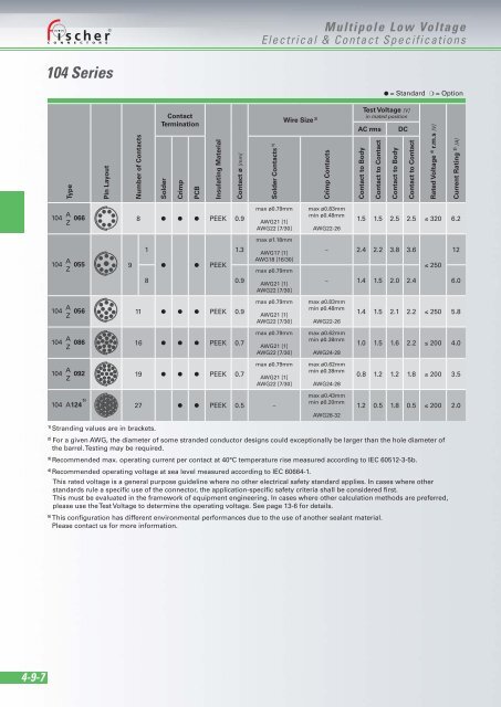
104 Series<br />
Type<br />
104 A 066<br />
Z<br />
104 A 055<br />
Z<br />
104 A 056<br />
Z<br />
104 A 086<br />
Z<br />
104 A 092<br />
Z<br />
104 A 124 5)<br />
Pin Layout<br />
Number of Contacts<br />
1) Stranding values are in brackets.<br />
9<br />
Contact<br />
Termination<br />
Solder<br />
Crimp<br />
PCB<br />
Insulating Material<br />
Contact ø [mm]<br />
8 ● ● ● PEEK 0.9<br />
1<br />
● ● PEEK<br />
1.3<br />
8 0.9<br />
11 ● ● ● PEEK 0.9<br />
16 ● ● ● PEEK 0.7<br />
19 ● ● ● PEEK 0.7<br />
Solder Contacts 1)<br />
max ø0.79mm<br />
AWG21 [1]<br />
AWG22 [7/30]<br />
max ø1.18mm<br />
AWG17 [1]<br />
AWG18 [16/30]<br />
max ø0.79mm<br />
AWG21 [1]<br />
AWG22 [7/30]<br />
max ø0.79mm<br />
AWG21 [1]<br />
AWG22 [7/30]<br />
max ø0.79mm<br />
AWG21 [1]<br />
AWG22 [7/30]<br />
max ø0.79mm<br />
AWG21 [1]<br />
AWG22 [7/30]<br />
27 ● ● PEEK 0.5 –<br />
Multipole Low Voltage<br />
Electrical & Contact Specifications<br />
Wire Size 2)<br />
Crimp Contacts<br />
max ø0.83mm<br />
min ø0.48mm<br />
AWG22-26<br />
Test Voltage [V]<br />
in mated position<br />
AC rms DC<br />
Contact to Body<br />
Contact to Contact<br />
Contact to Body<br />
Contact to Contact<br />
Rated Voltage 4) r.m.s [V]<br />
Current Rating 3) [A]<br />
1.5 1.5 2.5 2.5 ≤ 320 6.2<br />
– 2.4 2.2 3.8 3.6<br />
≤ 250<br />
12<br />
– 1.4 1.5 2.0 2.4 6.0<br />
max ø0.83mm<br />
min ø0.48mm<br />
AWG22-26<br />
max ø0.62mm<br />
min ø0.38mm<br />
AWG24-28<br />
max ø0.62mm<br />
min ø0.38mm<br />
AWG24-28<br />
max ø0.43mm<br />
min ø0.20mm<br />
AWG28-32<br />
● = Standard ❍ = Option<br />
1.4 1.5 2.1 2.2 ≤ 250 5.8<br />
1.0 1.5 1.6 2.2 ≤ 200 4.0<br />
0.8 1.2 1.2 1.8 ≤ 200 3.5<br />
1.2 0.5 1.8 0.5 ≤ 200 2.0<br />
2) For a given AWG, the diameter of some stranded conductor designs could exceptionally be larger than the hole diameter of<br />
the barrel. Testing may be required.<br />
3) Recommended max. operating current per contact at 40°C temperature rise measured according to IEC 60512-3-5b.<br />
4) Recommended operating voltage at sea level measured according to IEC 60664-1.<br />
This rated voltage is a general purpose guideline where no other electrical safety standard applies. In cases where other<br />
standards rule a specific use of the connector, the application-specific safety criteria shall be considered first.<br />
This must be evaluated in the framework of equipment engineering. In cases where other calculation methods are preferred,<br />
please use the Test Voltage to determine the operating voltage. See page 13-6 for details.<br />
5) This configuration has different environmental performances due to the use of another sealant material.<br />
Please contact us for more information.