Download - Fischer Connectors
Download - Fischer Connectors
Download - Fischer Connectors

You also want an ePaper? Increase the reach of your titles
YUMPU automatically turns print PDFs into web optimized ePapers that Google loves.
Multipole Low Voltage<br />
Electrical & Contact Specifications<br />
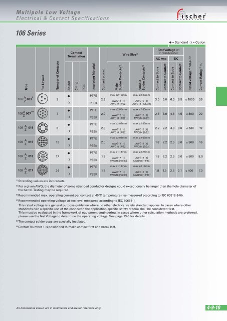
106 Series<br />
Type<br />
106 A 003 5)<br />
Z<br />
106 A 5) 6)<br />
007<br />
Z<br />
106 A 019<br />
Z<br />
106 A 015<br />
Z<br />
106 A 018<br />
Z<br />
106 A 017<br />
Z<br />
Pin Layout<br />
Number of Contacts<br />
3<br />
7<br />
8<br />
12<br />
17<br />
24<br />
1) Stranding values are in brackets.<br />
Contact<br />
Termination<br />
Solder<br />
●<br />
❍<br />
●<br />
❍<br />
●<br />
❍<br />
●<br />
❍<br />
●<br />
❍<br />
●<br />
❍<br />
Crimp<br />
PCB<br />
Insulating Material<br />
PTFE<br />
PEEK<br />
PTFE<br />
PEEK<br />
PTFE<br />
PEEK<br />
PTFE<br />
PEEK<br />
PTFE<br />
PEEK<br />
PTFE<br />
PEEK<br />
Contact ø [mm]<br />
2.3<br />
2.0<br />
2.0<br />
2.0<br />
1.3<br />
1.3<br />
Male<br />
Solder Contacts 1)<br />
max ø2.13mm<br />
AWG12 [1]<br />
AWG14 [7/22]<br />
max ø2.08mm<br />
AWG12 [1]<br />
AWG14 [7/22]<br />
max ø2.08mm<br />
AWG12 [1]<br />
AWG14 [7/22]<br />
max ø2.08mm<br />
AWG12 [1]<br />
AWG14 [7/22]<br />
max ø1.18mm<br />
AWG17 [1]<br />
AWG18 [16/30]<br />
max ø1.18mm<br />
AWG17 [1]<br />
AWG18 [16/30]<br />
Wire Size 2)<br />
Female<br />
Solder Contacts 1)<br />
max ø2.28mm<br />
AWG12 [1]<br />
AWG14 [105/34]<br />
max ø2.03mm<br />
AWG13 [1]<br />
AWG14 [7/22]<br />
max ø2.03mm<br />
AWG13 [1]<br />
AWG14 [7/22]<br />
max ø2.03mm<br />
AWG13 [1]<br />
AWG14 [7/22]<br />
max ø1.23mm<br />
AWG17 [1]<br />
AWG18 [16/30]<br />
max ø1.18mm<br />
AWG17 [1]<br />
AWG18 [16/30]<br />
Test Voltage [V]<br />
in mated position<br />
AC rms DC<br />
Contact to Body<br />
Contact to Contact<br />
Contact to Body<br />
Contact to Contact<br />
Rated Voltage 4) r.m.s [V]<br />
Current Rating 3) [A]<br />
3.5 5.0 6.0 6.5 ≤ 1000 26<br />
2.5 3.0 4.5 4.5 ≤ 800 20<br />
2.2 2.2 4.0 3.0 ≤ 630 19<br />
1.8 2.2 2.5 3.0 ≤ 500 16<br />
1.8 2.2 2.5 3.0 ≤ 500 8.0<br />
1.8 1.5 2.5 2.1 ≤ 400 7.0<br />
2) For a given AWG, the diameter of some stranded conductor designs could exceptionally be larger than the hole diameter of<br />
the barrel. Testing may be required.<br />
3) Recommended max. operating current per contact at 40°C temperature rise measured according to IEC 60512-3-5b.<br />
4) Recommended operating voltage at sea level measured according to IEC 60664-1.<br />
This rated voltage is a general purpose guideline where no other electrical safety standard applies. In cases where other<br />
standards rule a specific use of the connector, the application-specific safety criteria shall be considered first.<br />
This must be evaluated in the framework of equipment engineering. In cases where other calculation methods are preferred,<br />
please use the Test Voltage to determine the operating voltage. See page 13-6 for details.<br />
5) The contact solder cups are specially insulated.<br />
6) Contact Number 1 is positioned to make contact first and break last.<br />
All dimensions shown are in millimeters and are for reference only.<br />
● = Standard ❍ = Option<br />
4-9-10