Comfort 820 - Marantec
Comfort 820 - Marantec
Comfort 820 - Marantec

You also want an ePaper? Increase the reach of your titles
YUMPU automatically turns print PDFs into web optimized ePapers that Google loves.
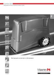
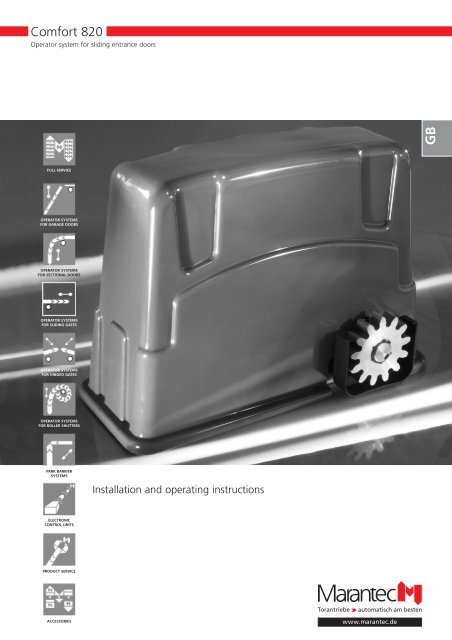
<strong>Comfort</strong> <strong>820</strong><br />
Operator system for sliding entrance doors<br />
FULL-SERVICE<br />
OPERATOR SYSTEMS<br />
FOR GARAGE DOORS<br />
OPERATOR SYSTEMS<br />
FOR SECTIONAL DOORS<br />
OPERATOR SYSTEMS<br />
FOR SLIDING GATES<br />
OPERATOR SYSTEMS<br />
FOR HINGED GATES<br />
OPERATOR SYSTEMS<br />
FOR ROLLER SHUTTERS<br />
PARK BARRIER<br />
SYSTEMS<br />
ELECTRONIC<br />
CONTROL UNITS<br />
PRODUCT SERVICE<br />
ACCESSORIES<br />
Installation and operating instructions<br />
GB
1. Meaning of symbols<br />
Symbols for control unit and operator Advice<br />
Photocell<br />
End position OPEN<br />
Automatic timer function<br />
End position CLOSED<br />
Control reference point<br />
Malfunction<br />
Impulse<br />
Operation, voltage<br />
Closing edge safety device<br />
Stop<br />
External control elements<br />
Electronic aerial<br />
Caution!<br />
Danger of personal injuries!<br />
The following safety advice must be<br />
observed at all times so as to avoid<br />
personal injuries!<br />
Attention!<br />
Danger of material damage!<br />
The following safety advice must be<br />
observed at all times so as to avoid<br />
material damages!<br />
Advice / Tip<br />
Control<br />
Reference<br />
2 Installation and operating instructions <strong>Comfort</strong> <strong>820</strong> GB (#70663)<br />
i<br />
Type plate control unit<br />
Type:<br />
Art.-No.:<br />
Product-No.:<br />
Type plate operator<br />
Typ:<br />
Art.-No.:<br />
Product-No.:
2. Table of contents<br />
1. Meaning of symbols . . . . . . . . . . . . . . . . . . . . . . . . . . . . . . . . . . . . . . . . . . . . . . . . . . . . . . . . . . . . . . . . . . . .2<br />
2. Table of contents . . . . . . . . . . . . . . . . . . . . . . . . . . . . . . . . . . . . . . . . . . . . . . . . . . . . . . . . . . . . . . . . . . . . . . .3<br />
3. General safety advice . . . . . . . . . . . . . . . . . . . . . . . . . . . . . . . . . . . . . . . . . . . . . . . . . . . . . . . . . . . . . . . . . . .4<br />
4. Summary of the product . . . . . . . . . . . . . . . . . . . . . . . . . . . . . . . . . . . . . . . . . . . . . . . . . . . . . . . . . . . . . . . .6<br />
4.1 Supply package <strong>Comfort</strong> <strong>820</strong> . . . . . . . . . . . . . . . . . . . . . . . . . . . . . . . . . . . . . . . . . . . . . . . . . . . . . . . . .6<br />
4.2 Mounting variations . . . . . . . . . . . . . . . . . . . . . . . . . . . . . . . . . . . . . . . . . . . . . . . . . . . . . . . . . . . . . . . . .8<br />
5. Preparation for mounting . . . . . . . . . . . . . . . . . . . . . . . . . . . . . . . . . . . . . . . . . . . . . . . . . . . . . . . . . . . . . . .9<br />
5.1 General notes . . . . . . . . . . . . . . . . . . . . . . . . . . . . . . . . . . . . . . . . . . . . . . . . . . . . . . . . . . . . . . . . . . . . .9<br />
5.2 Checks . . . . . . . . . . . . . . . . . . . . . . . . . . . . . . . . . . . . . . . . . . . . . . . . . . . . . . . . . . . . . . . . . . . . . . . . . . .9<br />
5.3 Plan of door and foundation . . . . . . . . . . . . . . . . . . . . . . . . . . . . . . . . . . . . . . . . . . . . . . . . . . . . . . . . .10<br />
6. Mounting . . . . . . . . . . . . . . . . . . . . . . . . . . . . . . . . . . . . . . . . . . . . . . . . . . . . . . . . . . . . . . . . . . . . . . . . . . . .11<br />
6.1 Mounting the spur gear . . . . . . . . . . . . . . . . . . . . . . . . . . . . . . . . . . . . . . . . . . . . . . . . . . . . . . . . . . . . .11<br />
6.2 Mounting the support brackets . . . . . . . . . . . . . . . . . . . . . . . . . . . . . . . . . . . . . . . . . . . . . . . . . . . . . . .12<br />
6.3 Cabling of the operator . . . . . . . . . . . . . . . . . . . . . . . . . . . . . . . . . . . . . . . . . . . . . . . . . . . . . . . . . . . . .16<br />
6.4 Adjustment of the toothed rack . . . . . . . . . . . . . . . . . . . . . . . . . . . . . . . . . . . . . . . . . . . . . . . . . . . . . .17<br />
6.5 Mounting the toothed rack . . . . . . . . . . . . . . . . . . . . . . . . . . . . . . . . . . . . . . . . . . . . . . . . . . . . . . . . . .20<br />
6.6 Mounting the reference point magnet . . . . . . . . . . . . . . . . . . . . . . . . . . . . . . . . . . . . . . . . . . . . . . . . . .25<br />
6.7 Emergency release in case of power failure . . . . . . . . . . . . . . . . . . . . . . . . . . . . . . . . . . . . . . . . . . . . . .28<br />
6.8 Mounting the cover . . . . . . . . . . . . . . . . . . . . . . . . . . . . . . . . . . . . . . . . . . . . . . . . . . . . . . . . . . . . . . . .29<br />
6.9 Connection of external control elements . . . . . . . . . . . . . . . . . . . . . . . . . . . . . . . . . . . . . . . . . . . . . . .31<br />
7. Hand transmitter . . . . . . . . . . . . . . . . . . . . . . . . . . . . . . . . . . . . . . . . . . . . . . . . . . . . . . . . . . . . . . . . . . . . . .32<br />
7.1 Operation and accessories . . . . . . . . . . . . . . . . . . . . . . . . . . . . . . . . . . . . . . . . . . . . . . . . . . . . . . . . . . .32<br />
7.2 Coding of the hand transmitters . . . . . . . . . . . . . . . . . . . . . . . . . . . . . . . . . . . . . . . . . . . . . . . . . . . . . .33<br />
8. Control unit . . . . . . . . . . . . . . . . . . . . . . . . . . . . . . . . . . . . . . . . . . . . . . . . . . . . . . . . . . . . . . . . . . . . . . . . . .36<br />
8.1 Overview of the control unit . . . . . . . . . . . . . . . . . . . . . . . . . . . . . . . . . . . . . . . . . . . . . . . . . . . . . . . . .36<br />
8.2 Overview on the display functions . . . . . . . . . . . . . . . . . . . . . . . . . . . . . . . . . . . . . . . . . . . . . . . . . . . . .37<br />
9. Programming . . . . . . . . . . . . . . . . . . . . . . . . . . . . . . . . . . . . . . . . . . . . . . . . . . . . . . . . . . . . . . . . . . . . . . . . .38<br />
9.1 General notes on programming . . . . . . . . . . . . . . . . . . . . . . . . . . . . . . . . . . . . . . . . . . . . . . . . . . . . . . .38<br />
9.2 Programming of the basic level . . . . . . . . . . . . . . . . . . . . . . . . . . . . . . . . . . . . . . . . . . . . . . . . . . . . . . .40<br />
9.3 Extended operator functions (only for specialist personnel) . . . . . . . . . . . . . . . . . . . . . . . . . . . . . . . . . .46<br />
10. Messages . . . . . . . . . . . . . . . . . . . . . . . . . . . . . . . . . . . . . . . . . . . . . . . . . . . . . . . . . . . . . . . . . . . . . . . . . . . .52<br />
10.1 Display of the messages . . . . . . . . . . . . . . . . . . . . . . . . . . . . . . . . . . . . . . . . . . . . . . . . . . . . . . . . . . . .52<br />
10.2 Overview of the error numbers . . . . . . . . . . . . . . . . . . . . . . . . . . . . . . . . . . . . . . . . . . . . . . . . . . . . . . .53<br />
10.3 Trouble-shooting . . . . . . . . . . . . . . . . . . . . . . . . . . . . . . . . . . . . . . . . . . . . . . . . . . . . . . . . . . . . . . . . . .54<br />
11. Appendix . . . . . . . . . . . . . . . . . . . . . . . . . . . . . . . . . . . . . . . . . . . . . . . . . . . . . . . . . . . . . . . . . . . . . . . . . . . .56<br />
11.1 Wiring plan <strong>Comfort</strong> <strong>820</strong> . . . . . . . . . . . . . . . . . . . . . . . . . . . . . . . . . . . . . . . . . . . . . . . . . . . . . . . . . . . .56<br />
11.2 Summary on spare parts <strong>Comfort</strong> <strong>820</strong> . . . . . . . . . . . . . . . . . . . . . . . . . . . . . . . . . . . . . . . . . . . . . . . . . .58<br />
11.3 Technical details <strong>Comfort</strong> <strong>820</strong> . . . . . . . . . . . . . . . . . . . . . . . . . . . . . . . . . . . . . . . . . . . . . . . . . . . . . . . .60<br />
11.4 Manufacturer's Declaration . . . . . . . . . . . . . . . . . . . . . . . . . . . . . . . . . . . . . . . . . . . . . . . . . . . . . . . . . .61<br />
11.5 EC Declaration of Conformity . . . . . . . . . . . . . . . . . . . . . . . . . . . . . . . . . . . . . . . . . . . . . . . . . . . . . . . .61<br />
Installation and operating instructions <strong>Comfort</strong> <strong>820</strong> GB (#70663)3
3. General safety advice<br />
Please read carefully!<br />
Target group<br />
Mounting, installation and initial operation of this operator may only be carried out by specialist personnel!<br />
Qualified and trained specialist personnel are persons<br />
• who have knowledge of the general and special safety regulations,<br />
• who have knowledge of the relevant electro-technical regulations,<br />
• with training in the use and maintenance of suitable safety equipment,<br />
• with sufficient training and supervision by electricians,<br />
• who are able to recognize the special hazards involved when working with electricity.<br />
Warranty<br />
For a warranty with respect to functioning and safety the advices in these instructions have to be observed.<br />
Disregarding these warnings may lead to personal injuries or material damages. The manufacturer will not be liable<br />
for damages that might occur when neglecting this advice.<br />
Batteries, fuses and bulbs are excluded from warranty.<br />
To avoid installation mistakes and damages to the door and operator please follow exactly the mounting advice in these<br />
installation instructions. The system may only be used after thorough information on the respective mounting and<br />
installation instructions.<br />
Please keep these installation and operating instructions for further use. They contain important advice for operation,<br />
checks and maintenance.<br />
This item is produced according to the directives and standards mentioned in the Manufacturer's Declaration and in the<br />
Declaration of Conformity. The product has left the factory in perfect condition with regard to safety.<br />
Power-driven windows, doors and gates for industrial use must be checked before initial operation and if necessary,<br />
but at least once a year by a specialist (with documentation in writing)!<br />
Correct use<br />
The operator is meant to be used exclusively to open and close sliding entrance doors.<br />
Beside the advice in these instructions please observe the general precautions and safety regulations!<br />
Our sales and supply terms and conditions are effective.<br />
4 Installation and operating instructions <strong>Comfort</strong> <strong>820</strong> GB (#70663)
3. General safety advice<br />
Please read carefully!<br />
Advice for installation of the operator<br />
• Make sure that the door is in mechanical good condition.<br />
• Make sure, that the door is balanced.<br />
• Make sure that the door opens and closes correctly.<br />
• Remove all components that are not required (e.g. cords, chains, angles etc.).<br />
• Switch off all devices which will not be needed after the operator is installed.<br />
• Before cabling works the operator has to be disconnected by all means from power supply and a waiting time<br />
of 10 sec. has to be kept in order to be sure that the operator is without power.<br />
• Observe the local safety regulations.<br />
• Always lay mains and control cables separately. The control voltage is 24 V DC.<br />
• Only mount the operator when the door is closed.<br />
• Install all impulse and control devices (e.g. RC code keypad) within sight to the door and in a safe distance to<br />
movable parts of the door. A minimum mounting height of 1,5 m has to be kept.<br />
• Following installation, ensure that door parts do not protrude onto public footpaths or streets.<br />
Advice for initial operation of the operator<br />
After initial operation, the door system operating personnel or their proxies must be familiarised with the use of the<br />
system<br />
• Make sure that no child will play with the door control unit.<br />
• Before movement of the door make sure that there are neither persons nor objects in the operating grange of the<br />
door.<br />
• Test all existing emergency command devices.<br />
• Never insert your hands into a running door or moving parts.<br />
Advice for maintenance of the operator<br />
To guarantee a function without faults, check and, if necessary, repair the following points. Always disconnect<br />
the operator from power supply before carrying out any works at the door system.<br />
• Check monthly whether the operator reverses as soon as the door meets an obstacle. For this put a 50 mm high /<br />
wide obstacle in the door travel path.<br />
• Check the settings of the "OPEN" and "CLOSE" power limit.<br />
• Check all movable parts of the door and operator system.<br />
• Check the door system for signs of wear or damages.<br />
• Check whether the door can be easily moved by hand.<br />
Advice for cleaning the operator<br />
For cleaning never use: direct jet of water, high pressure cleaner, acids or lye.<br />
• Clean the operator with a dry cloth if necessary.<br />
Installation and operating instructions <strong>Comfort</strong> <strong>820</strong> GB (#70663)5
4. Summary of the product<br />
4.1 Supply package <strong>Comfort</strong> <strong>820</strong><br />
Standard supply package Spur gears incl. trap protection<br />
4.1 / 1<br />
C<br />
E F<br />
A Operator<br />
B Cover<br />
C Magnet holder kit<br />
D Hand transmitter<br />
E Learning plug<br />
F Visor clip<br />
G Key for emergency release<br />
H Plugs<br />
A B<br />
D G H<br />
Beside the standard supply package the following<br />
accessories are necessary for mounting:<br />
- Spur gear<br />
- Toothed rack<br />
- Support bracket<br />
The operator can be mounted with two different spur<br />
gears.<br />
6 Installation and operating instructions <strong>Comfort</strong> <strong>820</strong> GB (#70663)<br />
4.1 / 2<br />
Modul 4<br />
Requires the combination with a rail M4.<br />
Modul 6<br />
Requires the combination with a rail M6.
4. Summary of the product<br />
Toothed racks<br />
The operator can be combined with seven different<br />
toothed racks.<br />
Special 431 (M4) + Special 433 (M6)<br />
Aluminium toothed rack profile<br />
with plastic toothed rack segment<br />
4.1 / 3<br />
I J<br />
I<br />
K<br />
K<br />
L<br />
Special 432 (M4) + Special 434 (M6)<br />
Steel toothed rack profile<br />
with plastic toothed rack segment<br />
4.1 / 4<br />
J<br />
L<br />
M<br />
M<br />
Special 441 (M4) + Special 443 (M6)<br />
Aluminium toothed rack profile with plastic<br />
toothed rack segments and cable duct<br />
4.1 / 5<br />
The supply package of the toothed rack contains:<br />
I Toothed rack profile<br />
J Plastic toothed rack segment<br />
K Fixing screws<br />
L End position damper<br />
M Clamping device<br />
N Plastic toothed rack with steel core<br />
The quantity of the supplied components depends on<br />
the door length.<br />
Special 471<br />
Plastic toothed rack with steel core<br />
Advice!<br />
The toothed rack Special 471 cannot<br />
be combined with the swivel support.<br />
Installation and operating instructions <strong>Comfort</strong> <strong>820</strong> GB (#70663)7<br />
4.1 / 6<br />
I J<br />
K<br />
L<br />
M
4. Summary of the product<br />
Support brackets<br />
The operator can be mounted with two different<br />
supports.<br />
Floor console<br />
4.1 / 7<br />
Swivel support<br />
4.1 / 8<br />
Advice!<br />
The swivel support cannot be combined<br />
with the toothed rack Special 471.<br />
4.2 Mounting variations<br />
The operator can be mounted in two different<br />
variations.<br />
Mounting the operator with floor console<br />
Mounting the operator with swivel support<br />
8 Installation and operating instructions <strong>Comfort</strong> <strong>820</strong> GB (#70663)<br />
4.2 / 1<br />
4.2 / 2<br />
270<br />
120<br />
328<br />
390
5. Preparation for mounting<br />
5.1 General notes<br />
The pictures in these instructions are not true-to-scale.<br />
The sizes are always indicated in millimetres (mm)!<br />
Depending on the opening direction the operator can<br />
be mounted on the right or on the left side of the<br />
door. These instructions show the mounting on the<br />
right side.<br />
For correct mounting you will need the following tools:<br />
5.1 / 1<br />
13<br />
ø 8 ø 10<br />
ø 7 6<br />
5 2<br />
ø 3,5 ø 4,5<br />
5.2 Checks<br />
Attention!<br />
Before you start to work, please always<br />
check the following points in order to<br />
guarantee correct mounting.<br />
Supply package<br />
• Check whether the supply package is complete.<br />
• Check whether all accessories required for your<br />
installation situation are at hand:<br />
- Spur gear<br />
- Toothed rack<br />
- Support bracket<br />
Foundation<br />
• Check the intended position of the operator:<br />
- The mounting of the operator must be carried out<br />
on the inside with the door closed.<br />
• - The operator must not be mounted in the<br />
clearance (q)!<br />
• Check whether there is a suitable foundation.<br />
• Check the laying of the supply line.<br />
Pay attention that the cable comes out on operator<br />
position (A). The minimum requirement for the earth<br />
cable is 3x1,5 mm 2 .<br />
Door<br />
• Check whether the sliding gate to be operated fulfils<br />
the following conditions:<br />
- The door has to be mounted horizontally, i.e. no<br />
slope in travel direction.<br />
• - In closed position the door should project the clear<br />
driveway by at least 250 mm on the installation<br />
side.<br />
- The door needs a mechanical end stop in both<br />
directions.<br />
• - The closing edges must be equipped with a flexible<br />
door sealing profile.<br />
Installation and operating instructions <strong>Comfort</strong> <strong>820</strong> GB (#70663)9
5. Preparation for mounting<br />
5.3 Plan of door and foundation<br />
5.3 / 1<br />
p<br />
q<br />
r<br />
A Empty conduit for supply line / control cable<br />
B Control cable<br />
C Supply line<br />
p Door length<br />
q Clear driveway<br />
r Opening direction<br />
s Frost-proof depth<br />
x Thickness of the door + distance to the wall<br />
A<br />
10 Installation and operating instructions <strong>Comfort</strong> <strong>820</strong> GB (#70663)<br />
≥ 250<br />
380<br />
s<br />
x<br />
B<br />
C<br />
X<br />
101<br />
60<br />
≥ 250 + x<br />
≥ 640<br />
X
6. Mounting<br />
6.1 Mounting the spur gear<br />
6.1 / 1<br />
• Mount the spur gear kit to the operator.<br />
Installation and operating instructions <strong>Comfort</strong> <strong>820</strong> GB (#70663)11
6. Mounting<br />
6.2 Mounting the support brackets<br />
6.2.1 Operator with floor console<br />
6.2.1 / 1<br />
M10 x 40<br />
• Screw the adjustment screws into the floor console.<br />
6.2.1 / 2<br />
M8 x 20<br />
Attention!<br />
To lay the cables correctly, the opening<br />
in the floor console (A) has to be<br />
aligned to the cable outlet of the<br />
operator!<br />
A<br />
• Screw the operator to the floor console.<br />
6.2.1 / 3<br />
• Remove the cover of the operator.<br />
• Take off the aerial.<br />
Attention!<br />
Lift the cover carefully because the aerial<br />
may be torn.<br />
• Punch the plastic seals (B) for the control cable and<br />
supply line with a sharp screw driver.<br />
12 Installation and operating instructions <strong>Comfort</strong> <strong>820</strong> GB (#70663)<br />
B<br />
B
6. Mounting<br />
6.2.1 / 4<br />
q<br />
E<br />
H<br />
15<br />
≥ 80<br />
Attention!<br />
The console must be aligned to the<br />
door so that the spur gear will grap into<br />
the toothed rack in every door position.<br />
C<br />
300<br />
360<br />
390<br />
G<br />
D<br />
F<br />
C Wall<br />
D Door<br />
E Screw area for the toothed rack<br />
F Empty conduit for supply line / control cable<br />
G Floor console<br />
H Foundation<br />
q Clear driveway<br />
• Align the floor console with the operator parallel<br />
to the door.<br />
• Measure the distance from the screw area<br />
of the toothed rack (E) to the operator.<br />
Observe measurement X.<br />
Special 431 + Special 433: X = 104<br />
Special 432 + Special 434: X = 104<br />
Special 441 + Special 443 X = 104<br />
Special 471: X = 114<br />
• Drill the holes for the dowels according to the<br />
indicated drilling scheme.<br />
X<br />
6.2.1 / 5<br />
• Insert the dowels.<br />
• Guide the control cable (I) and the supply line (J)<br />
through the floor console and through the opening<br />
in the operator.<br />
• Fix the floor console.<br />
I J<br />
Installation and operating instructions <strong>Comfort</strong> <strong>820</strong> GB (#70663)13<br />
40<br />
50<br />
ø 8
6. Mounting<br />
6.2.2 Operator with swivel support<br />
6.2.2/ 1<br />
q<br />
E<br />
Attention!<br />
The support must be aligned to the<br />
door so that the spur gear will grap into<br />
the toothed rack in every door position<br />
H<br />
80<br />
C<br />
360<br />
≥ 380<br />
F<br />
G<br />
D<br />
C Wall<br />
D Door<br />
E Screw area for the toothed rack<br />
F Empty conduit for supply line / control cable<br />
G Swivel support<br />
H Foundation<br />
q Clear driveway<br />
• Align the swivel support flush with the door.<br />
• Measure the distance from the screw area<br />
of the toothed rack (E) to the operator.<br />
Observe measurement X.<br />
Special 431 + Special 433: X = 104<br />
Special 432 + Special 434: X = 104<br />
Special 441 + Special 443 X = 104<br />
Special 471: not possible<br />
• Drill the holes according to the indicated drilling<br />
scheme.<br />
17<br />
50<br />
90<br />
108<br />
X<br />
6.2.2 / 2<br />
10 x 70<br />
• Mount the swivel support.<br />
6.2.2 / 3<br />
Attention!<br />
To maintain the swivel function,<br />
the support angel must be movable<br />
after fixing.<br />
• Screw the support angle to the operator.<br />
14 Installation and operating instructions <strong>Comfort</strong> <strong>820</strong> GB (#70663)<br />
M10
6. Mounting<br />
6.2.2 / 4<br />
Attention!<br />
Lift the cover carefully because the aerial<br />
may be torn.<br />
• Remove the cover of the operator.<br />
B<br />
• Punch the plastic seals (B) for the control cable and<br />
supply line with a sharp screw driver.<br />
6.2.2 / 5<br />
B 6.2.2 / 6<br />
• Guide the control cable (I) and the supply line (J)<br />
through the swivel support and through the opening<br />
in the operator<br />
• Put the operator into the swivel support.<br />
M10 x 20<br />
Advice!<br />
For a correct installation the operator<br />
must be shimmed so that it is aligned<br />
horizontally.<br />
• Shim the operator to a horizontal position.<br />
• Screw on the swivel support.<br />
Installation and operating instructions <strong>Comfort</strong> <strong>820</strong> GB (#70663)15<br />
I<br />
J
6. Mounting<br />
6.3 Cabling of the operator<br />
• Connect the supply line meeting your mounting<br />
situation:<br />
Mounting the operator inside right-hand side<br />
(supplied version)<br />
6.3 / 1<br />
Mounting the operator inside left-hand side<br />
6.3 / 2<br />
Legend cabling plans:<br />
C Motor capacitor<br />
H40 Signal light<br />
M1 Motor with thermal overload protection<br />
X1 Power line (from building)<br />
bk black<br />
bl blue<br />
rd red<br />
wt white<br />
vi violet<br />
bn brown<br />
ye yellow<br />
• Connect the control unit with the control line<br />
according to cabling plan (point 6.10).<br />
• Connect the aerial (C).<br />
• Mount the cover (B) to the operator.<br />
• Insert the plugs (A).<br />
16 Installation and operating instructions <strong>Comfort</strong> <strong>820</strong> GB (#70663)<br />
6.3 / 3<br />
A<br />
B<br />
C
6. Mounting<br />
6.4 Adjustment of the toothed rack<br />
6.4.1 Special 431 / Special 432 /<br />
Special 433 / Special 434 /<br />
Special 441 / Special 443<br />
6.4.1 / 1<br />
p<br />
The toothed rack profiles are supplied in two standard<br />
lengths: 2.000 mm and 4.000 mm.<br />
In the ideal case the door length (p) corresponds to the<br />
sum of the joined standard lengths. Then a change of<br />
the profiles is not necessary.<br />
In case the door length does not correspond to one of<br />
the standard lengths:<br />
• Join the toothed rack profiles.<br />
• Mark the door length (p).<br />
A projection can be cut with a metal saw<br />
(only if necessary).<br />
6.4.1 / 2<br />
To mount the first end position damper:<br />
• Drill two holes for the screws of the clamping device.<br />
6.4.1 / 3<br />
• Insert the end position dampers (A) and the clamping<br />
device (B) into the toothed rack profile.<br />
• Screw on the clamping device (B).<br />
Installation and operating instructions <strong>Comfort</strong> <strong>820</strong> GB (#70663)17<br />
ø7<br />
A<br />
15<br />
10<br />
B<br />
15
6. Mounting<br />
6.4.1 / 4<br />
• Join the toothed rack segments until the required<br />
measurement (q = door length - approx. 160 mm)<br />
is reached.<br />
In case the segments are longer than the necessary<br />
length:<br />
• Cut the projecting part.<br />
6.4.1 / 5<br />
q<br />
• Slide the toothed rack segments into the toothed<br />
rack segment profile.<br />
6.4.1 / 6<br />
• Insert the end position dampers (A) and the clamping<br />
device (B) into the toothed rack profile.<br />
6.4.1 / 7<br />
B A<br />
Attention!<br />
The toothed rack segments must have<br />
a slight tension in the completely<br />
mounted toothed rack.<br />
Otherwise malfunction and damages to<br />
the toothed rack could result.<br />
To mount the second end position damper:<br />
• Press the clamping device (B) into the profile until the<br />
toothed rack segments (C) are under slight tension.<br />
• Mark the two drill points of the clamping device on<br />
the profile.<br />
18 Installation and operating instructions <strong>Comfort</strong> <strong>820</strong> GB (#70663)<br />
B<br />
C
6. Mounting<br />
6.4.1 / 8<br />
B<br />
• Pull the clamping device (B) and the end position<br />
damper (A) out of the toothed rack profile.<br />
• Drill the two holes you marked before to screw on<br />
the clamping device.<br />
6.4.1 / 9<br />
B<br />
A<br />
A<br />
• Insert the end position dampers (A) and the clamping<br />
device (B) again into the toothed rack profile.<br />
• Screw on the clamping device (B).<br />
6.4.2 Special 471<br />
6.4.2 / 1<br />
• Assemble as much toothed rack segments as<br />
required in length for your door situation.<br />
6.4.2 / 2<br />
Any projecting part can be cut with a metal saw<br />
(only if necessary).<br />
Reference:<br />
For mounting the magnet holder please<br />
look up chapter 6.6.<br />
Installation and operating instructions <strong>Comfort</strong> <strong>820</strong> GB (#70663)19<br />
i<br />
Before mounting the toothed rack to the door the<br />
magnet holder has to be mounted to the toothed rack.<br />
• Mount the magnet holder to the toothed rack.
6. Mounting<br />
6.5 Mounting the toothed rack<br />
6.5.1 Preparation<br />
i<br />
6.5.1 / 1<br />
• Move the door to the CLOSED position.<br />
6.5.1 / 2<br />
Attention!<br />
To get a correct function of the system,<br />
observe the following points:<br />
- The console must be firmly screwed<br />
to the floor.<br />
- The operator must be firmly screwed<br />
to the console.<br />
- The operator must be unlocked.<br />
- It must be possible to move the door<br />
by hand.<br />
Reference:<br />
To unlock the operator please look up<br />
chapter 6.7.<br />
Attention:<br />
To guarantee a correct door travel<br />
the screws must be tightened and sunk<br />
flush.<br />
The five toothed rack versions (A) require different<br />
screw points to the door (B):<br />
Special 431 / 433 + Special 441 / 433<br />
Aluminium version<br />
6.5.1 / 3<br />
Special 432 + Special 434<br />
Steel version<br />
6.5.1 / 4<br />
6.5.1 / 5<br />
B A<br />
100 360 360 100<br />
20 Installation and operating instructions <strong>Comfort</strong> <strong>820</strong> GB (#70663)<br />
B<br />
A<br />
100 360 360 100<br />
Special 471<br />
Plastic version<br />
B A<br />
240 100 240 100 240
6. Mounting<br />
6.5.2 Operator with floor console<br />
6.5.2 / 1<br />
A<br />
Attention!<br />
To guarantee a correct door travel:<br />
- the rail has to be screwed to the door<br />
in the matching height,<br />
- the support has to be aligned parallel<br />
to the door.<br />
The matching height of the rail depends on the<br />
toothed rack.<br />
Special 431: 170 mm (+/- 10 mm)<br />
Special 432: 170 mm (+/- 10 mm)<br />
Special 433: 170 mm (+/- 10 mm)<br />
Special 434: 170 mm (+/- 10 mm)<br />
Special 441: 180 mm (+/- 10 mm)<br />
Special 443: 180 mm (+/- 10 mm)<br />
Special 471: 150 mm (+/- 10 mm)<br />
With differences of more than 10 mm:<br />
• Mount a suitable device to the door.<br />
For fine adjustment (+/- 10 mm) the height of the<br />
operator can be changed with the screws (A).<br />
6.5.2 / 2<br />
• Put the toothed rack onto the spur gear so that it<br />
grabs.<br />
• Align the toothed rack horizontally.<br />
• Use a clamp to fix the rail on the other side.<br />
Installation and operating instructions <strong>Comfort</strong> <strong>820</strong> GB (#70663)21
6. Mounting<br />
6.5.2 / 3<br />
6.5.2 / 4<br />
Attention:<br />
For a correct door travel it is important<br />
to keep a distance of 1 - 2 mm<br />
between the toothed rack and the spur<br />
gear.<br />
1-2<br />
• Fix the toothed rack at the first screw point<br />
according to the respective drill pattern.<br />
100<br />
6.5.2 / 5<br />
• Loosen the clamp.<br />
• Open the door by approx. 500 mm at a time.<br />
• Then fix the toothed rack to the currently open door<br />
section and screw it on according the respective drill<br />
pattern.<br />
6.5.2 / 6<br />
• Open the door completely.<br />
• Fix the toothed rack to the last section and screw<br />
it on according to the respective drill pattern.<br />
Test:<br />
The door has to be moved once to the<br />
OPEN position and once to the CLOSED<br />
position in order to check whether the<br />
rail engages with the spur gear on its<br />
total length.<br />
22 Installation and operating instructions <strong>Comfort</strong> <strong>820</strong> GB (#70663)
6. Mounting<br />
6.5.3 Operator with swivel support<br />
6.5.3 / 1<br />
With differences of more than 10 mm:<br />
• Mount a suitable device to the door.<br />
6.5.3 / 2<br />
• Open the door half.<br />
Attention!<br />
To guarantee a correct door travel,<br />
the toothed rack has to be screwed<br />
to the door in the matching height.<br />
The matching height of the rail depends on the<br />
toothed rack.<br />
Special 431: 170 mm (+/- 10 mm)<br />
Special 432: 170 mm (+/- 10 mm)<br />
Special 433: 170 mm (+/- 10 mm)<br />
Special 434: 170 mm (+/- 10 mm)<br />
Special 441: 180 mm (+/- 10 mm)<br />
Special 443: 180 mm (+/- 10 mm)<br />
Special 471: not possible<br />
6.5.3 / 3<br />
• Mount the rail support for the swivel support in<br />
the uppermost position. Only tighten the screws<br />
by hand.<br />
6.5.3 / 4<br />
<br />
• Insert the toothed rack between the spur gear and<br />
the rail support for the swivel support.<br />
<br />
Installation and operating instructions <strong>Comfort</strong> <strong>820</strong> GB (#70663)23
6. Mounting<br />
6.5.3 / 5<br />
• Align the toothed rack horizontally.<br />
• Fix the toothed rack with clamps.<br />
6.5.3 / 6<br />
Attention:<br />
For a correct door travel it is important<br />
to keep a distance of 1 - 2 mm<br />
between the toothed rack and the spur<br />
gear.<br />
6.5.3 / 7<br />
• Push the rail support for the swivel support so far<br />
down that it lies firmly on the toothed rack.<br />
<br />
1-2<br />
• Screw the toothed rack to the complete door<br />
according to the drill pattern that matches to your<br />
toothed rack.<br />
• Screw the rail support for the swivel support firmly<br />
to the operator.<br />
6.5.3 / 8<br />
• Remove the lining.<br />
Attention!<br />
Take care that there are no objects<br />
under the operator because otherwise<br />
the swivel function will be disturbed.<br />
Test:<br />
The door has to be moved once to the<br />
OPEN position and once to the CLOSED<br />
position in order to check whether the<br />
rail engages with the spur gear on its<br />
total length.<br />
24 Installation and operating instructions <strong>Comfort</strong> <strong>820</strong> GB (#70663)
6. Mounting<br />
6.6 Mounting the reference point<br />
magnet<br />
6.6.1 Preparation<br />
6.6.1 / 1<br />
Attention!<br />
In order to make an operation of the<br />
system without dangers possible, the<br />
door needs a mechanical end stop to<br />
both directions.<br />
The door operator is cut-out in the end positions<br />
"door open" and "door closed" without mechanical<br />
end switches but with electronic microprocessor<br />
control. An incremental transmitter that is integrated<br />
in the operator is activated by a magnet and registers<br />
the actual door position.<br />
800-1000<br />
• Determine the position for the reference point<br />
magnet.<br />
The magnet for the reference point sensor is<br />
two-colored.<br />
Always mount the magnet with the green side to the<br />
operator.<br />
6.6.2 Operator with floor console<br />
The mounting of the magnet depends on the toothed<br />
rack used.<br />
Special 431 + Special 433<br />
Version: aluminium without cable duct<br />
6.6.2 / 1<br />
B4,2 x 19<br />
B4,2 x 25<br />
Special 432 + Special 434<br />
Steel version<br />
6.6.2 / 2<br />
B4,2 x 19<br />
B4,2 x 25<br />
Special 441 + Special 443<br />
Version: aluminium with cable duct<br />
6.6.2 / 3<br />
B4,2 x 19<br />
B4,2 x 25<br />
• Mount the magnet to the magnet holder.<br />
• Mount the magnet holder to the toothed rack at the<br />
determined position.<br />
Installation and operating instructions <strong>Comfort</strong> <strong>820</strong> GB (#70663)25
6. Mounting<br />
Special 471<br />
Plastic toothed rack with steel core<br />
6.6.2 / 4<br />
B4,2 x 25<br />
B4,2 x 9,5<br />
• Mount the magnet to the magnet holder.<br />
• Mount the magnet holder to the toothed rack<br />
at the determined position, so that the magnet lies<br />
on the toothed rack.<br />
6.6.2 / 5<br />
26 Installation and operating instructions <strong>Comfort</strong> <strong>820</strong> GB (#70663)<br />
3 - 7<br />
• Check the position of the reference point magnet.<br />
6.6.2 / 6<br />
Attention!<br />
The distance between the magnet (A)<br />
and the reference point sensor (B) must<br />
be 15 - 25 mm!<br />
Please keep this measurement by all<br />
means in order to avoid malfunctions!<br />
A<br />
15 - 25<br />
B<br />
• Check the distance between magnet (A) and<br />
reference point sensor (B).
6. Mounting<br />
6.6.3 Operator with swivel support<br />
The mounting of the magnet depends on the toothed<br />
rack used.<br />
Special 431 + Special 433<br />
Version: aluminium without cable duct<br />
6.6.3 / 1<br />
B4,2 x 19<br />
B4,2 x 25<br />
Special 432 + Special 434<br />
Steel version<br />
6.6.3 / 2<br />
B4,2 x 19<br />
B4,2 x 25<br />
Special 441 + Special 443<br />
Version: aluminium with cable duct<br />
6.6.3 / 3<br />
B4,2 x 19<br />
B4,2 x 25<br />
• Mount the magnet to the magnet holder.<br />
• Mount the magnet holder to the support plate.<br />
• Mount the magnet holder to the toothed rack at the<br />
determined position.<br />
6.6.3 / 4<br />
Installation and operating instructions <strong>Comfort</strong> <strong>820</strong> GB (#70663)27<br />
0 ± 2<br />
• Check the position of the reference point magnet.<br />
6.6.3 / 5<br />
Attention!<br />
The distance between the magnet (A)<br />
and the reference point sensor (B) must<br />
be 15 - 25 mm!<br />
Please keep this measurement by all<br />
means in order to avoid malfunctions!<br />
A<br />
C<br />
15 - 25<br />
B<br />
• Check the distance between magnet (A) and<br />
reference point sensor (B).
6. Mounting<br />
6.7 Emergency release in case<br />
of power failure<br />
Unlocking<br />
6.7 / 1<br />
• Remove screw (A).<br />
6.7 / 2<br />
B<br />
A<br />
• Turn the emergency release lever (B) to the right side<br />
by means of the enclosed wrench.<br />
• Screw the emergency release lever with screw (A) to<br />
the new position.<br />
The gear is now separated mechanically and the door<br />
can be moved by hand. At the same time the control<br />
unit is cut out.<br />
Locking<br />
• Remove screw (A).<br />
A A<br />
• Turn the emergency release lever (B) to the left side<br />
by means of the enclosed wrench.<br />
• Screw the emergency release lever with screw (A) to<br />
the new position.<br />
The gear is now connected mechanically with the drive<br />
shaft and the door can be power-operated. At the<br />
same time the control unit is switched on.<br />
28 Installation and operating instructions <strong>Comfort</strong> <strong>820</strong> GB (#70663)<br />
6.7 / 3<br />
6.7 / 4<br />
B<br />
A
6. Mounting<br />
6.8 Mounting the cover<br />
6.8.1 Programming cover<br />
6.8.1 / 1<br />
• Remove the programming cover (A).<br />
6.8.1 / 2<br />
A<br />
Advice:<br />
After programming of the operator the<br />
programming cover must be put back.<br />
B<br />
• Mount the programming cover (A).<br />
• Insert the plugs (B).<br />
A<br />
6.8.2 Protective cover<br />
Advice:<br />
To protect the operator against weather<br />
influences the operator must be<br />
covered with the protective cover after<br />
programming and mounting of the<br />
programming cover.<br />
Operator with floor console<br />
6.8.2 / 1<br />
• Put the protective cover (B) on the operator.<br />
Installation and operating instructions <strong>Comfort</strong> <strong>820</strong> GB (#70663)29<br />
B
6. Mounting<br />
Operator with swivel support<br />
6.8.2 / 2<br />
C<br />
Advice:<br />
To mount the protective cover to<br />
an operator with swivel support, the<br />
cover has to be adapted accordingly.<br />
The cover can only protect the system<br />
if the required openings are as small as<br />
possible.<br />
B<br />
• Cut the areas that are marked in grey (C) as shown<br />
in the picture.<br />
• Put the protective cover (B) on the operator.<br />
30 Installation and operating instructions <strong>Comfort</strong> <strong>820</strong> GB (#70663)
6. Mounting<br />
6.9 Connection of external control elements<br />
6.9 / 1<br />
i<br />
Attention!<br />
To avoid damages to the control unit:<br />
- only connect potential-free closing contacts to the terminals 1 and 2 (A).<br />
- don't insert the short-circuit plug (C) into socked (E)!<br />
G<br />
A<br />
A Connection of control elements on site without <strong>Marantec</strong> system cabling only to the connecting terminals:<br />
1 GND<br />
2 Impulse<br />
3 24 V DC max. 50 mA<br />
B Socket for "external closing edge safety device"<br />
When connecting any element the short-circuit plug (C) must be removed.<br />
C Short-circuit plug<br />
D Socket for "external control elements"<br />
When connecting any element the short-circuit plug (C) must be removed.<br />
E Socket for "electronic aerial" or "external photocell"<br />
F Connection cable electronic aerial<br />
G Fuse for control unit (4A)<br />
Reference:<br />
To install external control elements please look up the respective instructions.<br />
Installation and operating instructions <strong>Comfort</strong> <strong>820</strong> GB (#70663)31<br />
+<br />
P<br />
B C D E F<br />
A<br />
1 2 3
7. Hand transmitter<br />
7.1 Operation and accessories<br />
Operation<br />
7.1 / 1<br />
Caution!<br />
Children are not allowed to operate<br />
the hand transmitters!<br />
Before operating the hand transmitter<br />
make sure that there are neither<br />
persons nor objects in the operating<br />
range of the door.<br />
A Operating button<br />
B Operating button<br />
C Battery - transmission control light<br />
D Socket for learning plug<br />
E Back of hand transmitter<br />
F Battery 3V CR 2032<br />
The operating buttons (A + B) can be programmed<br />
with different functions.<br />
Possible functions are for example:<br />
Operating button A:<br />
Impulse for door OPEN / door CLOSE<br />
Operating button B:<br />
External light<br />
i<br />
D<br />
B<br />
C<br />
A<br />
D<br />
Reference:<br />
The programming of the hand<br />
transmitters (RC remote controls)<br />
for the operator control unit used is<br />
described in chapter 9.2.7.<br />
Change batteries<br />
• Open the back of the hand transmitter (E) e.g.<br />
with a coin.<br />
• Change the battery (F) and observe right poling.<br />
32 Installation and operating instructions <strong>Comfort</strong> <strong>820</strong> GB (#70663)<br />
7.1 / 2<br />
Accessory<br />
7.1 / 3<br />
1<br />
F<br />
E<br />
Visor clip to attach the hand transmitter to a visor<br />
in the car.
7. Hand transmitter<br />
7.2 Coding of the hand transmitters<br />
7.2.1 Learn coding<br />
This function is meant to transfer the coding of<br />
an existing hand transmitter (Master) to an additional<br />
hand transmitter.<br />
7.2.1 / 1<br />
Caution!<br />
Before operating the hand transmitter<br />
please make sure that there are neither<br />
persons nor objects in the operating<br />
range of the door.<br />
• Connect both transmitters with the enclosed learning<br />
plug.<br />
Advice!<br />
The plug connections on both sides<br />
of the hand transmitter can be used<br />
identically.<br />
7.2.1 / 2<br />
• Actuate the master transmitter and hold the button.<br />
The LED on the transmitter is on.<br />
7.2.1 / 3<br />
• Actuate the desired button on the new hand<br />
transmitter while still holding the button on the<br />
master transmitter.<br />
After 1 - 2 sec. the LED on the new transmitter glows<br />
permanently.<br />
The programming is finished.<br />
The new hand transmitter has now taken over the<br />
coding of the master transmitter.<br />
• Remove the learning plug.<br />
Advice!<br />
For multi-channel hand transmitters<br />
the coding process has to be carried<br />
out for every single button separately.<br />
Installation and operating instructions <strong>Comfort</strong> <strong>820</strong> GB (#70663)33
7. Hand transmitter<br />
7.2.2 Change coding<br />
This function is meant to change the coding of<br />
the remote control in case a hand transmitter has<br />
gone lost.<br />
7.2.2 / 1<br />
• Insert the learning plug into the hand transmitter.<br />
• Short-circuit one of the two outer pins of the<br />
learning plug with the centre lead (e.g. by means<br />
of a screwdriver).<br />
• Actuate the desired button on the hand transmitter.<br />
The integrated random programming determines a<br />
new coding.<br />
The LED is flashing quickly.<br />
As soon as the LED on the hand transmitter glows<br />
permanently, you can release the button on the<br />
transmitter and remove the learning plug.<br />
Advice!<br />
After a new coding of the hand<br />
transmitter the operator for the sliding<br />
gate has to be re-programmed as well<br />
to the new coding as the old coding<br />
has gone lost irrevocably.<br />
For multi-channel hand transmitters the<br />
coding process has to be carried out for<br />
every single button separately.<br />
34 Installation and operating instructions <strong>Comfort</strong> <strong>820</strong> GB (#70663)
Installation and operating instructions <strong>Comfort</strong> <strong>820</strong> GB (#70663)35
8. Control unit<br />
8.1 Overview of the control unit<br />
8.1 / 1<br />
G<br />
F<br />
H A<br />
8<br />
1<br />
2<br />
7 3<br />
6<br />
5 4<br />
1 2 3<br />
E<br />
LED display<br />
A LED for external photocell (only programming)<br />
B LED "OPEN door"<br />
C LED automatic timer function<br />
D LED "CLOSE door"<br />
E LED reference point<br />
F LED malfunction<br />
G LED impulse<br />
H LED voltage<br />
B C I K<br />
Operating elements<br />
I Button + (e.g. to travel the door to the OPEN position or to increase values)<br />
J Button - (e.g. to travel the door to the CLOSE position or to reduce values)<br />
K Button P (e.g. to save values)<br />
D<br />
36 Installation and operating instructions <strong>Comfort</strong> <strong>820</strong> GB (#70663)<br />
P<br />
J
8. Control unit<br />
8.2 Overview on the display functions<br />
Explanation of the LED's<br />
LED off<br />
LED on<br />
LED flashing slowly<br />
LED flashing quickly<br />
After switching on the power the control unit carries<br />
out a self-test:<br />
All LED's glow up for approx. 3 sec.<br />
LED displays in operating mode<br />
Door in end position OPEN<br />
Door in intermediate position OPEN<br />
Signal light is on<br />
Signal light is flashing<br />
Door in end position CLOSED<br />
Door in intermediate position CLOSED<br />
Door passes the reference point<br />
Permanent actuation of a control element<br />
Malfunction<br />
RC remote control is actuated<br />
Operating voltage<br />
Installation and operating instructions <strong>Comfort</strong> <strong>820</strong> GB (#70663)37
9. Programming<br />
9.1 General notes on programming<br />
The programming is carried out with the buttons +, -,<br />
and P.<br />
If none of the buttons is actuated within 120 sec. in<br />
programming mode, the control unit changes back to<br />
the operating mode.<br />
An error message is displayed accordingly.<br />
9.1.1 Programming levels<br />
The programming of the operator is divided in two<br />
areas:<br />
1. Programming of the basic level:<br />
The basic functions of the operator are programmed<br />
in this level. This programming process is carried out<br />
consecutively and it is compulsory.<br />
To come to the programming of the basic level,<br />
button P must be pressed longer than 2 sec. but less<br />
than 10 sec..<br />
LED 2 is flashing.<br />
2. Programming of the extended<br />
operator functions:<br />
The programming of the extended operator functions<br />
may only be carried out by specialist personnel.<br />
As soon as the button P is pressed longer than 10 sec.,<br />
the control unit changes to the programming of the<br />
extended operator functions.<br />
LED 2 is then flashing quickly.<br />
Advice:<br />
In the extended operator functions<br />
important factory settings can be<br />
changed.<br />
38 Installation and operating instructions <strong>Comfort</strong> <strong>820</strong> GB (#70663)
9. Programming<br />
9.1.2 Reference point<br />
The following is displayed:<br />
In operating mode<br />
The LED shortly lights up when the reference<br />
point is passed<br />
In programming mode<br />
Advice:<br />
The control unit can only be<br />
programmed when the reference point<br />
has been passed electrically.<br />
Therefore the door has to be travelled<br />
1x to the end position OPEN and 1x to<br />
the end position CLOSED before first<br />
programming.<br />
The operator is between the reference point<br />
and the end position OPEN.<br />
The operator is between the reference point<br />
and the end position CLOSED.<br />
9.1.3 Setting the door positions<br />
The programming of the "end position OPEN" and<br />
"end position CLOSED" can be carried out in two ways:<br />
1. Coarse adjustment by permanently holding<br />
a button<br />
The setting is carried out when button + or - is pressed<br />
permanently.<br />
The door travels correspondingly to the OPEN or<br />
CLOSED position.<br />
2. Fine adjustment by a short button impulse<br />
The setting is carried out by a short button impulse<br />
on button + or -. The door does not move during this<br />
procedure.<br />
Every time the button is pressed the end position is<br />
shifted by 4 mm to the respective direction.<br />
To test the end position, the door has to be traveled<br />
over the reference point to the OPEN position or to the<br />
CLOSED position.<br />
During the button impulse the LED 7<br />
is flashing quickly.<br />
Advice:<br />
The control unit travels without<br />
press-and-release.<br />
Legend:<br />
LED off<br />
LED on<br />
LED flashing slowly<br />
LED flashing quickly<br />
Installation and operating instructions <strong>Comfort</strong> <strong>820</strong> GB (#70663)39
9. Programming<br />
9.2 Programming of the basic level<br />
9.2.1 Programming of the "end position OPEN"<br />
1.<br />
2.<br />
3.<br />
4.<br />
5.<br />
6.<br />
7.<br />
8.<br />
9.<br />
The control unit is in<br />
operating mode.<br />
To change to the<br />
programming mode<br />
press button P:<br />
> 2 Sec. < 10 Sec.<br />
Do not hold button P<br />
longer than 10 sec.!<br />
The control unit is in<br />
menu 1 of the basic<br />
programming.<br />
Set the end position<br />
DOOR OPEN.<br />
The reference point<br />
must be passed 1x.<br />
Fine adjustment is carried<br />
out with impulse on<br />
button + or -.<br />
Press button P 1x:<br />
save the end position.<br />
Automatic change to<br />
the programming of the<br />
"end position CLOSED".<br />
9.2.2 Programming of the<br />
"intermediate position OPEN"<br />
40 Installation and operating instructions <strong>Comfort</strong> <strong>820</strong> GB (#70663)<br />
1.<br />
2.<br />
3.<br />
4.<br />
5.<br />
The control unit is in<br />
menu 2 of the basic<br />
programming.<br />
Set the intermediate<br />
position DOOR OPEN.<br />
Fine adjustment is<br />
carried out with impulse<br />
on button + or -.<br />
Press button P 1x:<br />
Save the intermediate<br />
position.<br />
Automatic change to<br />
the programming of the<br />
"intermediate position<br />
CLOSED".
9. Programming<br />
9.2.3 Programming of the<br />
"intermediate position CLOSED"<br />
1.<br />
2.<br />
3.<br />
4.<br />
5.<br />
The control unit is in<br />
menu 3 of the basic<br />
programming.<br />
Set the intermediate<br />
position DOOR CLOSED.<br />
Fine adjustment is<br />
carried out with impulse<br />
on button + or -.<br />
Press button P 1x:<br />
Save the intermediate<br />
position.<br />
Automatic change to<br />
the programming of the<br />
"end position<br />
CLOSED".<br />
9.2.4 Programming of the "end position CLOSED"<br />
Installation and operating instructions <strong>Comfort</strong> <strong>820</strong> GB (#70663)41<br />
1.<br />
2.<br />
3.<br />
4.<br />
5.<br />
Legend:<br />
LED off<br />
LED on<br />
The control unit is in<br />
menu 4 of the basic<br />
programming.<br />
Set end position DOOR<br />
CLOSED.<br />
The reference point<br />
must be passed 1x.<br />
Fine adjustment is carried<br />
out with impulse on<br />
button + or -.<br />
Press button P 1x:<br />
save the end position.<br />
Automatic change to<br />
the programming of<br />
"power limit OPEN".<br />
LED flashing slowly<br />
LED flashing quickly
9. Programming<br />
9.2.5 Programming of the "power limit OPEN" 9.2.6 Programming of the "power limit CLOSE"<br />
1.<br />
2.<br />
3.<br />
4.<br />
5.<br />
6.<br />
The control unit is in<br />
menu 5 of the basic<br />
programming.<br />
Press button + 1x:<br />
The current setting is<br />
displayed.<br />
Set the power limit as<br />
sensitive as possible.<br />
Press button + or -:<br />
Setting in steps from 1<br />
(sensitive) to 16.<br />
Press button P 1x:<br />
save the set value.<br />
Automatic change to<br />
the programming of the<br />
"power limit CLOSE".<br />
42 Installation and operating instructions <strong>Comfort</strong> <strong>820</strong> GB (#70663)<br />
1.<br />
2.<br />
3.<br />
4.<br />
5.<br />
6.<br />
The control unit is in<br />
menu 6 of the basic<br />
programming.<br />
Press button + 1x:<br />
The current setting is<br />
displayed.<br />
Set the power limit as<br />
sensitive as possible.<br />
Press button + or -:<br />
Setting in steps from<br />
1 (sensitive) to 16.<br />
Press button P 1x:<br />
save the set value.<br />
Automatic change to<br />
the programming of the<br />
"RC remote control".
9. Programming<br />
9.2.7 Programming of the "RC remote control"<br />
Function allocation of the storage places<br />
You can read in up to 5 differently coded functions:<br />
1. Function Impulse<br />
2. Function half OPEN<br />
3. Function half CLOSED<br />
4. Function OPEN<br />
5. Function CLOSE<br />
Select the programming of RC remote control<br />
1.<br />
2.<br />
3.<br />
The control unit is in<br />
menu 7 of the basic<br />
programming.<br />
Press button + 1x:<br />
The first storage place is<br />
selected.<br />
Press button P 1x:<br />
The next storage place<br />
is selected.<br />
Program the RC remote control<br />
(example storage place 1)<br />
Installation and operating instructions <strong>Comfort</strong> <strong>820</strong> GB (#70663)43<br />
1.<br />
2.<br />
3.<br />
4.<br />
5.<br />
The first storage place is<br />
selected.<br />
Press button + 1x:<br />
The selected storage<br />
place is ready to be<br />
programmed.<br />
Press the respective<br />
button on the hand<br />
transmitter.<br />
Press button P 1x:<br />
The coding of the hand<br />
transmitter is saved.<br />
Change to the next<br />
storage place.<br />
Advice:<br />
Wrongly programmed coding can be<br />
overwritten with a new coding.<br />
If necessary they can be deleted!<br />
Legend:<br />
LED off<br />
LED on<br />
LED flashing slowly<br />
LED flashing quickly
9. Programming<br />
Delete RC remote control - if necessary<br />
(example storage place 1)<br />
1.<br />
2.<br />
3.<br />
4.<br />
The first storage place is<br />
selected.<br />
Press button - 1x:<br />
The selected storage<br />
place is ready to be<br />
deleted.<br />
Press button P 1x:<br />
The coding of the selected<br />
storage place is<br />
deleted.<br />
Change to the next storage<br />
place.<br />
Finish the programming of the RC remote control<br />
44 Installation and operating instructions <strong>Comfort</strong> <strong>820</strong> GB (#70663)<br />
1.<br />
2.<br />
3.<br />
4.<br />
5.<br />
Press button P until the<br />
third storage place is<br />
selected.<br />
Press button P 1x:<br />
The programming of RC<br />
remote control is terminated.<br />
The control unit changes<br />
to the programming<br />
"reset factory settings".<br />
Press button P 1x:<br />
The programming of the<br />
basic level is terminated.<br />
The control unit is in<br />
operating mode.
9. Programming<br />
9.2.8 Programming of "reset factory settings"<br />
With the reset function all menus can be reset to the<br />
values already set from factory.<br />
1.<br />
2.<br />
3.<br />
4.<br />
5.<br />
6.<br />
7.<br />
8.<br />
9.<br />
The control unit is in<br />
operating mode.<br />
To change to the<br />
programming mode:<br />
press button P:<br />
> 2 Sec. < 10 Sec.<br />
Do not hold button P<br />
longer than 10 sec.!<br />
Press button P 7x to<br />
get to the menu<br />
"reset factory settings".<br />
Press button + or - 1x:<br />
Selection "no reset" -<br />
all set values remain<br />
unchanged.<br />
Press button - or + 1x:<br />
Selection "reset" -<br />
factory settings are<br />
restored.<br />
Press button P 1x:<br />
Save and terminate<br />
programming.<br />
New start when RESET<br />
has been selected:<br />
All LED's glow up for<br />
2 sec.<br />
The control unit is in<br />
operating mode.<br />
Legend:<br />
LED off<br />
LED on<br />
LED flashing slowly<br />
LED flashing quickly<br />
Installation and operating instructions <strong>Comfort</strong> <strong>820</strong> GB (#70663)45
9. Programming<br />
9.3 Extended operator functions (only for specialist personnel)<br />
9.3.1 Overview of the extended operator functions<br />
Level Functions Explanation Factory settings<br />
3rd programming<br />
level<br />
Automatic timer<br />
function<br />
4th programming<br />
level<br />
Parameter<br />
6th programming<br />
level<br />
Reversion<br />
modes<br />
8th programming<br />
level<br />
Operating<br />
modes<br />
Open door time The time the door is open before it closes automatically.<br />
Warning time<br />
Warning before start<br />
Early closing after having<br />
passed the photocell<br />
Signal lights<br />
Excess travel stop<br />
The time the signal light is flashing before the door<br />
closes automatically.<br />
The time the signal light flashes before the door starts<br />
to move.<br />
The door closes either after the set open time or earlier<br />
after having passed the photocell.<br />
The signal light function can be set to flashing or to<br />
permanent light.<br />
The time period after which the operator cuts out<br />
without having reached an end position.<br />
Automatic timer<br />
function deactivated<br />
Automatic timer<br />
function deactivated<br />
0 seconds<br />
46 Installation and operating instructions <strong>Comfort</strong> <strong>820</strong> GB (#70663)<br />
No<br />
Permanent light<br />
55 seconds<br />
Offset learned power limit The learned power limit can be set in steps from 1 - 16. Step 10<br />
Sensitivity power limit<br />
Power limit OPEN<br />
Power limit CLOSE<br />
Activation of photocell / photocell<br />
CLOSE<br />
Closing edge safety device<br />
OPEN<br />
Closing edge safety device<br />
CLOSE<br />
The sensitivity of the power limit can be set in steps<br />
from 1 - 16.<br />
Setting whether the operator stops, short or long<br />
reversion.<br />
Setting whether the operator stops, short or long<br />
reversion.<br />
Setting whether the operator stops, short or long<br />
reversion.<br />
Setting whether the operator stops, short or long<br />
reversion.<br />
Setting whether the operator stops, short or long<br />
reversion.<br />
press-and-release OPEN After start the operator runs to the selected position. On<br />
press-and-release CLOSE After start the operator runs to the selected position. On<br />
Impulse commands<br />
Direction commands<br />
(Pushbutton OPEN or CLOSE)<br />
Activation of the impulse button when the operator<br />
runs.<br />
Activation of the direction button when the operator<br />
runs.<br />
Step 6<br />
short reversion<br />
short reversion<br />
not existing<br />
not existing<br />
not existing<br />
Yes<br />
No
9. Programming<br />
9.3.2 Programming sequences of the extended<br />
operator functions<br />
1.<br />
2.<br />
3.<br />
4.<br />
5.<br />
6.<br />
7.<br />
8.<br />
9.<br />
The control unit is in<br />
operating mode.<br />
Press button P:<br />
> 10 Sec.<br />
Countdown from 8 to<br />
1, then all LED's are on.<br />
Release button P:<br />
The control unit is in the<br />
first level of the extended<br />
operator functions.<br />
Press button P 1x:<br />
Change to the next<br />
level of the extended<br />
functions.<br />
Press button + 1x:<br />
Change to the first<br />
menu of the selected<br />
level.<br />
Press button + 1x:<br />
Display of the current<br />
setting.<br />
Press button + or -:<br />
Change the current<br />
value.<br />
Press button P 1x:<br />
Save the value, display<br />
of the selected level.<br />
If P is pressed without<br />
changing the value,<br />
the setting remains<br />
unchanged!<br />
Installation and operating instructions <strong>Comfort</strong> <strong>820</strong> GB (#70663)47<br />
10.<br />
11.<br />
12.<br />
13.<br />
14.<br />
15.<br />
Legend:<br />
LED off<br />
LED on<br />
Press button P 1x:<br />
Change to the next<br />
menu in the selected<br />
level.<br />
After the last<br />
programming menu of<br />
the selected level the<br />
control unit displays the<br />
selected level.<br />
Press button P 1x:<br />
The control unit<br />
changes to the next<br />
level.<br />
After the last<br />
programming level the<br />
programming of the<br />
extended operator<br />
functions is terminated.<br />
Press button P 1x:<br />
The programming is<br />
terminated.<br />
The control unit is in<br />
operating mode.<br />
LED flashing slowly<br />
LED flashing quickly
9. Programming<br />
9.3.3 Programming level 3 - automatic timer function<br />
<br />
16<br />
15<br />
14<br />
13<br />
12<br />
11<br />
10<br />
9<br />
8<br />
7<br />
6<br />
5<br />
4<br />
3<br />
2<br />
1<br />
Menu 1: Open door time<br />
255<br />
Seconds<br />
180<br />
Seconds<br />
150<br />
Seconds<br />
120<br />
Seconds<br />
100<br />
Seconds<br />
80<br />
Seconds<br />
50<br />
Seconds<br />
40<br />
Seconds<br />
35<br />
Seconds<br />
30<br />
Seconds<br />
20<br />
Seconds<br />
25<br />
Seconds<br />
15<br />
Seconds<br />
10<br />
Seconds<br />
5<br />
Seconds<br />
Automatic<br />
timer<br />
function<br />
deactivated<br />
Menu 2: Warning time<br />
70<br />
Seconds<br />
65<br />
Seconds<br />
60<br />
Seconds<br />
55<br />
Seconds<br />
50<br />
Seconds<br />
45<br />
Seconds<br />
40<br />
Seconds<br />
35<br />
Seconds<br />
30<br />
Seconds<br />
25<br />
Seconds<br />
20<br />
Seconds<br />
15<br />
Seconds<br />
10<br />
Seconds<br />
5<br />
Seconds<br />
2<br />
Seconds<br />
Automatic<br />
timer<br />
function<br />
deactivated<br />
Menu 3: Warning before start<br />
7<br />
Seconds<br />
6<br />
Seconds<br />
5<br />
Seconds<br />
4<br />
Seconds<br />
3<br />
Seconds<br />
2<br />
Seconds<br />
1<br />
Seconds<br />
0<br />
Seconds<br />
9. Programming<br />
9.3.4 Programming level 4 - parameter<br />
<br />
16<br />
15<br />
14<br />
13<br />
12<br />
11<br />
10<br />
9<br />
8<br />
7<br />
6<br />
5<br />
4<br />
3<br />
2<br />
1<br />
Menu 1: Excess travel stop<br />
220<br />
Seconds<br />
220<br />
Seconds<br />
210<br />
Seconds<br />
200<br />
Seconds<br />
190<br />
Seconds<br />
180<br />
Seconds<br />
160<br />
Seconds<br />
140<br />
Seconds<br />
120<br />
Seconds<br />
100<br />
Seconds<br />
80<br />
Seconds<br />
65<br />
Seconds<br />
55<br />
Seconds<br />
50<br />
Seconds<br />
40<br />
Seconds<br />
30<br />
Seconds<br />
Menu 2: Offset learned power limit<br />
16<br />
15<br />
14<br />
13<br />
12<br />
11<br />
10<br />
9<br />
8<br />
7<br />
6<br />
5<br />
4<br />
3<br />
2<br />
1<br />
9. Programming<br />
9.3.5 Programming level 6 - reversion modes<br />
<br />
16<br />
15<br />
14<br />
13<br />
12<br />
11<br />
10<br />
9<br />
8<br />
7<br />
6<br />
5<br />
4<br />
3<br />
2<br />
1<br />
Menu 1: Power limit for OPEN direction<br />
not<br />
existing<br />
long<br />
reversion<br />
short<br />
reversion<br />
Stop<br />
Menu 2: Power limit for CLOSE direction<br />
not<br />
existing<br />
long<br />
reversion<br />
short<br />
reversion<br />
Stop<br />
Menu 4: Activation of photocell / photocell for CLOSE direction<br />
not<br />
existing<br />
long<br />
reversion<br />
short<br />
reversion<br />
Stop<br />
9. Programming<br />
9.3.6 Programming level 8 - operating modes<br />
<br />
16<br />
15<br />
14<br />
13<br />
12<br />
11<br />
10<br />
9<br />
8<br />
7<br />
6<br />
5<br />
4<br />
3<br />
2<br />
1<br />
Menu 1: press-and-release for OPEN direction<br />
ON<br />
OFF<br />
Menu 2: press-and-release for CLOSE direction<br />
ON<br />
OFF<br />
Menu 3: Impulse - command device active when operator runs<br />
10. Messages<br />
10.1 Display of the messages<br />
Messages at permanent actuation<br />
When actuating operating and safety elements<br />
permanently the current status of the system is<br />
displayed.<br />
1.<br />
2.<br />
Status displays<br />
The control light<br />
MALFUNCTION (6)<br />
glows.<br />
Press button P 1x:<br />
Display of the status<br />
(see below).<br />
IMPULSE button actuated<br />
OPEN button actuated<br />
Closing edge safety device OPEN actuated<br />
CLOSE button actuated<br />
Closing edge safety device CLOSE actuated<br />
Photocell actuated<br />
Static current circuit interrupted<br />
Messages at malfunctions<br />
Malfunctions in the system are displayed by a<br />
corresponding error number.<br />
52 Installation and operating instructions <strong>Comfort</strong> <strong>820</strong> GB (#70663)<br />
1.<br />
2.<br />
1.<br />
2.<br />
3.<br />
4.<br />
5.<br />
6.<br />
The control light<br />
MALFUNCTION (6) is<br />
flashing.<br />
Press button P 1x:<br />
Display of the error<br />
number (see 10.2).<br />
Message memory<br />
The message memory displays the last 5 messages of<br />
the control unit.<br />
Press button P:<br />
The LED's from<br />
1 - 8 are glowing.<br />
The control unit shows<br />
the current messages.<br />
Press button -:<br />
Old messages are<br />
displayed.<br />
Press button +:<br />
The current message is<br />
displayed.<br />
Press button P:<br />
The display of the<br />
message memory is<br />
finished.<br />
The control unit is in<br />
operating mode.
10. Messages<br />
10.2 Overview of the error numbers<br />
Number Message Display<br />
6 Photocell actuated<br />
7 Programming cancelled<br />
8 Reference point<br />
9 R.P.M sensor defective<br />
10 Power limit<br />
11 Excess travel stop<br />
12<br />
13<br />
15<br />
Testing<br />
closing edge safety device<br />
OPEN not o.k.<br />
Testing<br />
closing edge safety device<br />
CLOSE not o.k.<br />
Testing<br />
photocell not o.k.<br />
Number Message Display<br />
27 Sensitivity power limit<br />
Installation and operating instructions <strong>Comfort</strong> <strong>820</strong> GB (#70663)53<br />
28<br />
36<br />
Offset learned<br />
Power limit<br />
Static current circuit<br />
interrupted<br />
Legend:<br />
LED off<br />
LED on<br />
LED flashing slowly<br />
LED flashing quickly
10. Messages<br />
10.3 Trouble-shooting<br />
Error Cause Remedy<br />
LED 8 is not glowing. - No voltage. - Check voltage.<br />
- Check mains socket.<br />
- Fuse in the control unit defective. - Check control fuse in the operator (point 6.9).<br />
- Thermal overload protection in power<br />
transformer is active.<br />
- Have transformer cool down.<br />
- Operator is unlocked. - Lock emergency release.<br />
- Control unit defective. - Check control unit (point 6.2):<br />
Separate the operator from power supply / remove cover<br />
of housing / screw off control unit / pull the control unit a<br />
bit out / take off the connecting plug / take out the control<br />
unit.<br />
No reaction on impulse. - Connecting terminals for "Impulse"<br />
button bridged, e.g. by short circuit in<br />
cable or wrong connection.<br />
LED 6 is flashing regularly. - There is a malfunction. When shortly<br />
pressing the button P, one or several<br />
LED's start to flash irregularly.<br />
By adding the respective digits the<br />
error number is calculated.<br />
LED 6 / message 10 - Power limit set too sensitive.<br />
- Door travel too sluggish.<br />
- Door blocked.<br />
LED 6 / message 6 or 15 - External photocell defected or<br />
interrupted.<br />
- To test, separate possibly connected key switches or interior<br />
pushbuttons from the control unit (point 6.9):<br />
Pull the cable out of socket D, insert short-circuit plug (C)<br />
and look for mistakes in cabling.<br />
- Set power limit (point 9.2.5 / point 9.2.6) less sensitive.<br />
- Make door easily movable.<br />
- Remove obstacle or have photocell checked.<br />
54 Installation and operating instructions <strong>Comfort</strong> <strong>820</strong> GB (#70663)
10. Messages<br />
Error Cause Remedy<br />
LED 6 / message 9 - R.P.M. sensor defective. - Have operator checked.<br />
LED 6 / message 27 - Sensitivity power limit set too sensitive<br />
- Door travel too sluggish.<br />
- Door blocked.<br />
LED 6 / message 28 - Offset learned power limit set too<br />
sensitive.<br />
- Door travel too sluggish.<br />
- Door blocked.<br />
LED 6 / message 36 - Short-circuit plug has been removed<br />
(point 6.7), but Stop button not<br />
connected.<br />
Operator only runs to the<br />
OPEN position, but not to<br />
the CLOSE position /<br />
message 15.<br />
LED 7 is not flashing quickly<br />
after impulse from the hand<br />
transmitter.<br />
Operator does not react<br />
after impulse from the hand<br />
transmitter.<br />
- Photocell programmed, but no<br />
photocell connected.<br />
- Set sensitivity of power limit less sensitive<br />
(point 9.3.4 / menu 3).<br />
- Make door easily movable.<br />
- Set offset learned power limit less sensitive<br />
(point 9.3.4 / menu 2).<br />
- Make door easily movable.<br />
- Connect STOP button or insert plug (point 6.9).<br />
- Re-program photocell function (point 9.3.5 / menu 4)or<br />
connect photocell.<br />
- Electronic aerial not plugged in. - Connect aerial with control unit (point 6.9).<br />
- Hand transmitter coding does not<br />
match the receiver coding.<br />
- Check coding (point 9.2.7).<br />
- Battery in hand transmitter empty. - Exchange battery 3V CR 2032 (point 7.1).<br />
- Hand transmitter or control electronics<br />
or electronic aerial defective.<br />
- Not enough voltage of the hand<br />
transmitter battery.<br />
- Distance too large (range below 5 m).<br />
- Have all 3 components checked.<br />
- Exchange battery 3V CR 2032 (point 7.1).<br />
Installation and operating instructions <strong>Comfort</strong> <strong>820</strong> GB (#70663)55
11. Appendix<br />
11.1 Wiring plan <strong>Comfort</strong> <strong>820</strong><br />
11.1 / 1<br />
Attention!<br />
Please observe by all means the following points in order to avoid damages:<br />
- Always observe local safety regulations.<br />
- Always lay mains and control cables separately.<br />
- The control voltage is 24 V DC.<br />
- External voltage at sockets X2c, X10, X20 und X31 will completely destroy the electronics.<br />
C Motor capacitor<br />
F1 Fuse (max. 4A)<br />
H40 Signal light<br />
M1 Motor with thermal overload protection<br />
S Main switch 2<br />
S1 "Impulse" button 2<br />
S10 Switch for emergency hand operation<br />
S21 R.P.M. sensor<br />
S22 Reference point sensor<br />
X0 Mains socket 1<br />
X1 Mains supply line with plug 1<br />
Connecting terminals<br />
X2c Command devices<br />
Plug connections<br />
X10 external control elements<br />
X20 electronic aerial<br />
external photocell<br />
X31 Closing edge safety device "open" / "close"<br />
Connection plans for accessories<br />
SKS Closing edge safety device 3<br />
W20 electronic aerial<br />
XS10 external control elements 3<br />
1)on site<br />
2)if existing<br />
3)when connecting, remove short-circuit plug<br />
56 Installation and operating instructions <strong>Comfort</strong> <strong>820</strong> GB (#70663)
11. Appendix<br />
Installation and operating instructions <strong>Comfort</strong> <strong>820</strong> GB (#70663)57
11. Appendix<br />
11.2 Summary on spare parts <strong>Comfort</strong> <strong>820</strong><br />
11.2 / 1<br />
# 66 456<br />
#153 280 (M6) #8 005 382 (M4) #65 554 #152 168<br />
#45 366<br />
#8 004 755<br />
# 8 003 698<br />
#8 004 153<br />
#46 611<br />
#8 003 702<br />
#8 004 175<br />
#70 030<br />
#154 773<br />
#8 003 141<br />
#8 000 409<br />
#8 003 539<br />
#152 142<br />
58 Installation and operating instructions <strong>Comfort</strong> <strong>820</strong> GB (#70663)
11. Appendix<br />
Legend spare parts 11.2/1<br />
Art.-No. Description<br />
66456 Cover <strong>Comfort</strong> <strong>820</strong><br />
8004153 Cover seal<br />
46611 Plug kit<br />
8003702 Control unit cover<br />
8004175 Control unit cover seal<br />
8003698 Housing cover<br />
70030 Control unit <strong>Comfort</strong> <strong>820</strong><br />
154773 Cable kit reed sensor<br />
153280 Toothed rack segment M 6<br />
8005382 Toothed rack segment M 4<br />
6554 Switch magnet with bracket<br />
152168 Speed sensor circuit board<br />
8003141 Rocker lever with quick release<br />
800409 Safety washer RS 5<br />
8003539 Maintenance release<br />
152142 Axle SE<br />
45366 Counter bearing swivel support<br />
8004755 Finger trap protection<br />
Installation and operating instructions <strong>Comfort</strong> <strong>820</strong> GB (#70663)59
11. Appendix<br />
11.3 Technical details <strong>Comfort</strong> <strong>820</strong><br />
Electrical details<br />
- Nominal voltage 230 V<br />
- Nominal frequency 50 Hz<br />
- Power consumption 2,5 A<br />
- Power input operation 0,3 KW<br />
- Power input stand-by < 4 W<br />
- Operating mode<br />
(connection period)KB 4 Min.<br />
- Control voltage 24 V DC<br />
- Protection category motor unit IP 54<br />
- Protection class I<br />
Mechanical details<br />
- Push and pull force 800 N<br />
- Travel speed 180 mm/sec.<br />
- Opening time (door specific)approx. 22 sec.<br />
General details<br />
- Dimensions motor unit 330x270x120 mm<br />
- Weight 17,5 kg<br />
- Range of temperature -20 to +60 °C<br />
Supply package<br />
- Motor unit <strong>Comfort</strong> <strong>820</strong><br />
with integrated electronic control unit<br />
- Multibit remote control, 868MHz,<br />
incl. Digital 302 mini hand transmitter, 2-channel<br />
- Emergency release<br />
- Magnet holder kit<br />
- Protective cover<br />
Features / safety functions<br />
- Universal use for doors up to max. width of 8 m<br />
and max. weight of 750 kg<br />
- Reference point technology<br />
- Power limit<br />
- Anti-lock system<br />
- Excess travel stop<br />
- Automatic timer function<br />
- Electronic travel cut-out<br />
- Signal light connection<br />
- Connection for pushbuttons, code buttons and key<br />
switches<br />
- Part opening<br />
- Connection of potential-free limit switch message<br />
- Error messages<br />
Accessories<br />
- Multibit remote control<br />
- Separate module aerial, 868 MHz, IP 65<br />
- Signal light<br />
- Closing edge safety device<br />
- Photocell<br />
- Transponder systems<br />
- Key switch (pre-cabled)<br />
- Code button (pre-cabled)<br />
- Spur gear<br />
- Toothed rack<br />
EN 50081-1<br />
EN 50082-1<br />
EN 55014<br />
EN 61000-3-2<br />
EN 61000-3-3<br />
EN 60335-1<br />
EN 300220-1<br />
EN 301489-3<br />
ETS 300683<br />
60 Installation and operating instructions <strong>Comfort</strong> <strong>820</strong> GB (#70663)
11. Appendix<br />
11.4 Manufacturer's Declaration 11.5 EC Declaration of Conformity<br />
We herewith declare that the product mentioned<br />
below corresponds in its design, construction and<br />
version sold by us to the relevant and basic safety and<br />
health requirements of the following EC regulations:<br />
EMC Directive, Machinery Directive and Low Voltage<br />
Directive.<br />
In case of a product change that is not agreed upon<br />
by us this Declaration will be void.<br />
Product: <strong>Comfort</strong> <strong>820</strong><br />
Relevant EC Regulations:<br />
- EC EMC Directive (89/336/EWG, 93/68/EWG and<br />
93/44/EWG),<br />
- Machinery Directive<br />
(89/392/EWG, 91/368/EWG, 93/68/EWG and<br />
93/44/EWG) and<br />
- Low Voltage Directive<br />
(73/23/EWG, 93/68/EWG and 93/44/EWG).<br />
Applied harmonised standards, especially:<br />
EN 292-1<br />
EN 50081-1<br />
EN 50082-1<br />
EN 55014<br />
EN 61000-3-2<br />
EN 61000-3-3<br />
EN 60335-1<br />
EN 12445<br />
EN 12453<br />
EN 300220-1<br />
EN 301489-3<br />
ETS 300683<br />
31.07.2004 ppa. Molterer<br />
<strong>Marantec</strong> Antriebs- und Steuerungstechnik GmbH & Co. KG<br />
Remser Brook 11 · 33428 Marienfeld · Germany<br />
Fon +49 (52 47) 7 05-0<br />
We herewith declare that the product mentioned<br />
below corresponds in its design, construction and<br />
version sold by us to the relevant and basic safety and<br />
health requirements of the following EC regulations:<br />
EMC Directive, Machinery Directive and Low Voltage<br />
Directive.<br />
In case of a product change that is not agreed upon<br />
by us this Declaration will be void.<br />
Product:<br />
Relevant EC Regulations:<br />
- EC EMC Directive (89/336/EWG, 93/68/EWG and<br />
93/44/EWG),<br />
- Machinery Directive<br />
(89/392/EWG, 91/368/EWG, 93/68/EWG and<br />
93/44/EWG) and<br />
- Low Voltage Directive<br />
(73/23/EWG, 93/68/EWG and 93/44/EWG).<br />
Applied harmonised standards, especially:<br />
EN 292-1<br />
EN 50081-1<br />
EN 50082-1<br />
EN 55014<br />
EN 61000-3-2<br />
EN 61000-3-3<br />
EN 60335-1<br />
EN 12445<br />
EN 12453<br />
EN 300220-1<br />
EN 301489-3<br />
ETS 300683<br />
Date / Signature<br />
Installation and operating instructions <strong>Comfort</strong> <strong>820</strong> GB (#70663)61
11. Appendix<br />
62 Installation and operating instructions <strong>Comfort</strong> <strong>820</strong> GB (#70663)
11. Appendix<br />
Installation and operating instructions <strong>Comfort</strong> <strong>820</strong> GB (#70663)63
English Copyright.<br />
No part of this manual may be reproduced without our prior approval.<br />
Subject to alterations in the interests of technical progress.<br />
Version: 04.2005<br />
#70663<br />
1 - GB 360234 - M - 0.5 - 0604