South East Asia - WordPress.com - BluOcean.AdMedia
South East Asia - WordPress.com - BluOcean.AdMedia
South East Asia - WordPress.com - BluOcean.AdMedia

Create successful ePaper yourself
Turn your PDF publications into a flip-book with our unique Google optimized e-Paper software.
LED BIN validation & traceability<br />
Figure 4. Product flow control (PFC) assures data<br />
integrity while preventing defects.<br />
to automatically detect and identify the<br />
feeder at each slot (Figure 5). In addition<br />
to defect prevention, the smart feeder<br />
system automatically collects accurate<br />
traceability data during machine setup<br />
and replenishment. The deployment of<br />
smart feeders also increased productivity<br />
by replacing manual validation of line<br />
setup. By automating what was previously<br />
a manual procedure, Methode shaved 12<br />
minutes off the average line changeover<br />
time. With three changeovers typical<br />
over a 21-hour work day, this efficiency<br />
gain equates to 36 additional minutes of<br />
productive line runtime per day.<br />
Machine monitoring: low level<br />
alarms<br />
The TTC system is directly integrated with<br />
the placement machine’s software. This<br />
allows critical real-time production data to<br />
be shared between both systems yielding<br />
numerous benefits. For example, the<br />
machine will stop whenever there is a PN<br />
related setup error. Holding the machine<br />
in cycle stop until the fault is cleared.<br />
Figure 7. Automated calibration eliminates product variability.<br />
Figure 5. RFID smart feeders to poke yoke setup and<br />
reduce changeover time.<br />
Integration with the machine’s SW also<br />
allows the TTC system to accurately track<br />
<strong>com</strong>ponent consumption, including all<br />
miss picks and rejected <strong>com</strong>ponents,<br />
enabling proactive material management.<br />
The system issues an alarm when the<br />
remaining quantity of <strong>com</strong>ponents on any<br />
reel be<strong>com</strong>es lower than a set threshold.<br />
When a low quantity alarm is issued<br />
for an LED, the PFC upstream from the<br />
placement machine prevents additional<br />
boards from entering the machine. The<br />
operator is prompted to choose between<br />
replacing the low reel immediately, or<br />
resuming production with the current<br />
setup:<br />
• If the operator chooses to resume<br />
production using the current setup, the<br />
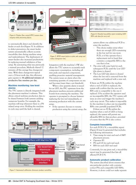
Figure 6. Detailed traceability report including LED<br />
BIN code data for every reel.<br />
system allows one additional PCB to<br />
enter the machine.<br />
– This choice makes sense when<br />
there are enough LEDs remaining<br />
in the low reel for one more<br />
PCB, or if the operator has a<br />
replacement reel in hand that<br />
contains a <strong>com</strong>patible BIN to the<br />
one that is low.<br />
• The error will <strong>com</strong>e back for each<br />
subsequent PCB, until the Low LED<br />
Qty alarm is cleared.<br />
• The Low LED Qty alarm is cleared<br />
when the low reel is removed from the<br />
machine and replaced with a new reel.<br />
If there are PCBs within the machine<br />
when a reel of LEDs is replaced, the<br />
system will confirm that the new reel’s<br />
BIN code is <strong>com</strong>patible to the one it<br />
replaced. If by accident the operator used<br />
an in<strong>com</strong>patible BIN, the TTC system will<br />
issue an error and trigger the machine’s<br />
cycle stop circuit. This makes it impossible<br />
for the machine to place any in<strong>com</strong>patible<br />
BINs onto partially populated PCBs.<br />
If there are no PCBs within the<br />
machine when a reel of LEDs is being<br />
replaced, the system will permit any<br />
allowable BIN for that product, provided<br />
of course that the PN is also correct.<br />
<strong>com</strong>plete traceability<br />
For each PCB S/N, a traceability report<br />
(Figure 6) may be generated that includes<br />
the following information:<br />
• Time stamp for start and end of SMT<br />
placement process.<br />
• Operator ID<br />
• PN and LN for each reel used.<br />
• BIN for each LED reel used<br />
Conversely, for any given reel, a traceability<br />
report may be generated that lists all<br />
affected PCB S/N.<br />
automatic product calibration<br />
The system described above ensures that<br />
any particular product only contains<br />
correct PNs and <strong>com</strong>patible LED BINs.<br />
However, it alone could not make separate<br />
22 – Global SMT & Packaging <strong>South</strong>east <strong>Asia</strong> – Winter 2010 www.globalsmtindia.in