AutoScan Spectrophotometer Instrument Operator's Manual - X-Rite
AutoScan Spectrophotometer Instrument Operator's Manual - X-Rite
AutoScan Spectrophotometer Instrument Operator's Manual - X-Rite

You also want an ePaper? Increase the reach of your titles
YUMPU automatically turns print PDFs into web optimized ePapers that Google loves.
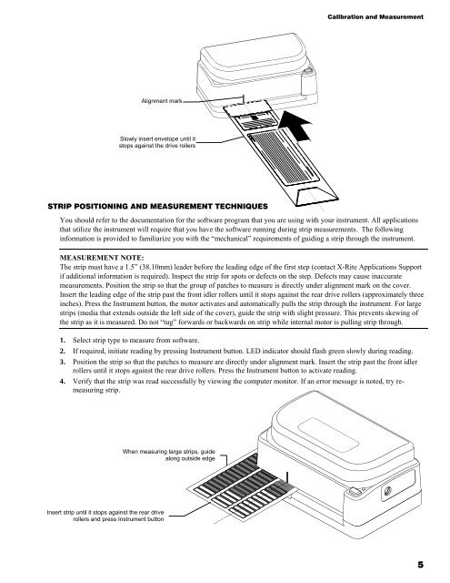
Alignment mark<br />
Slowly insert envelope until it<br />
stops against the drive rollers<br />
STRIP POSITIONING AND MEASUREMENT TECHNIQUES<br />
Calibration and Measurement<br />
You should refer to the documentation for the software program that you are using with your instrument. All applications<br />
that utilize the instrument will require that you have the software running during strip measurements. The following<br />
information is provided to familiarize you with the “mechanical” requirements of guiding a strip through the instrument.<br />
MEASUREMENT NOTE:<br />
The strip must have a 1.5” (38.10mm) leader before the leading edge of the first step (contact X-<strong>Rite</strong> Applications Support<br />
if additional information is required). Inspect the strip for spots or defects on the step. Defects may cause inaccurate<br />
measurements. Position the strip so that the group of patches to measure is directly under alignment mark on the cover.<br />
Insert the leading edge of the strip past the front idler rollers until it stops against the rear drive rollers (approximately three<br />
inches). Press the <strong>Instrument</strong> button, the motor activates and automatically pulls the strip through the instrument. For large<br />
strips (media that extends outside the left side of the cover), guide the strip with slight pressure. This prevents skewing of<br />
the strip as it is measured. Do not “tug” forwards or backwards on strip while internal motor is pulling strip through.<br />
1. Select strip type to measure from software.<br />
2. If required, initiate reading by pressing <strong>Instrument</strong> button. LED indicator should flash green slowly during reading.<br />
3. Position the strip so that the patches to measure are directly under alignment mark. Insert the strip past the front idler<br />
rollers until it stops against the rear drive rollers. Press the <strong>Instrument</strong> button to activate reading.<br />
4. Verify that the strip was read successfully by viewing the computer monitor. If an error message is noted, try remeasuring<br />
strip.<br />
Insert strip until it stops against the rear drive<br />
rollers and press <strong>Instrument</strong> button<br />
When measuring large strips, guide<br />
along outside edge<br />
5