Technology and Operation - Kernkraftwerk Gösgen
Technology and Operation - Kernkraftwerk Gösgen
Technology and Operation - Kernkraftwerk Gösgen

You also want an ePaper? Increase the reach of your titles
YUMPU automatically turns print PDFs into web optimized ePapers that Google loves.
Reactor coolant system<br />
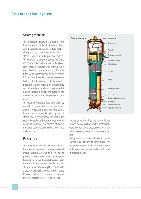
Steam generators<br />
The three steam generators transfer the heat<br />
from the reactor coolant to the water/steam<br />
circuit. Designed as st<strong>and</strong>ing U-tube heat exchangers,<br />
they convert feed water into live<br />
steam to drive the turbo-generator system.<br />
The collection chamber is connected to the<br />
reactor coolant circuit pipes via inlet <strong>and</strong> outlet<br />
nozzles. The reactor coolant flows out of<br />
the collection chamber <strong>and</strong> through the Utubes<br />
to the outlet chamber, giving off heat as<br />
it flows. From the outlet chamber, the coolant<br />
is directed to the primary coolant pump. The<br />
bundle of U-tubes, made of an exceptionally<br />
corrosion-resistant material, is supported at<br />
a large number of points <strong>and</strong> is rolled into<br />
<strong>and</strong> welded onto the steam generator’s tube<br />
plate.<br />
The incoming feed water flows downwards by<br />
natural circulation between the vessel wall<br />
<strong>and</strong> a shroud surrounding the tube bundle<br />
before moving upwards again, giving off<br />
steam, once it has absorbed the heat. In the<br />
steam dome above the tube plate, the residual<br />
steam moisture is separated off before<br />
the dried steam is eliminated through the<br />
outlet nozzle.<br />
Pressuriser<br />
The purpose of the pressuriser is to keep<br />
the operating pressure in the reactor coolant<br />
system constant. A change in the reactor<br />
power produces variations in the temperature<br />
<strong>and</strong> volume <strong>and</strong>, without a pressuriser,<br />
these would lead to pressure fluctuations.<br />
The pressuriser is an upright container with<br />
a capacity of 42 cubic metres, which is partly<br />
filled with water. It is connected up to one of<br />
the three reactor coolant loops via the pres-<br />
Steam generator<br />
suriser surge line. Pressure control is performed<br />
by means of an electric heater in the<br />
water section of the pressuriser <strong>and</strong> a facility<br />
for spraying water into the steam section.<br />
Using the spray system, the steam can be<br />
condensed <strong>and</strong> hence the pressure reduced.<br />
By generating heat with the electric heater<br />
rods, water can be evaporated <strong>and</strong> hence<br />
the pressure raised.<br />
Steam outlet<br />
Steam dryers<br />
Manhole<br />
Steam separators<br />
Feedwater inlet nozzle<br />
Feedwater ring line<br />
Heating tubes<br />
� � � � �14 � � � � � � � � � � � � � � � � � � � � � � � � � � � � � � � � � � � � � � � � � � � � � � � � � � � �<br />
Shroud<br />
Vessel<br />
Tube support grids<br />
H<strong>and</strong> hole<br />
Support <strong>and</strong> guide brackets<br />
Tube sheet<br />
Reactor coolant inlet<br />
Reactor coolant outlet