Hiniker 700 Manual - Snow Plow Stuff
Hiniker 700 Manual - Snow Plow Stuff
Hiniker 700 Manual - Snow Plow Stuff

You also want an ePaper? Increase the reach of your titles
YUMPU automatically turns print PDFs into web optimized ePapers that Google loves.
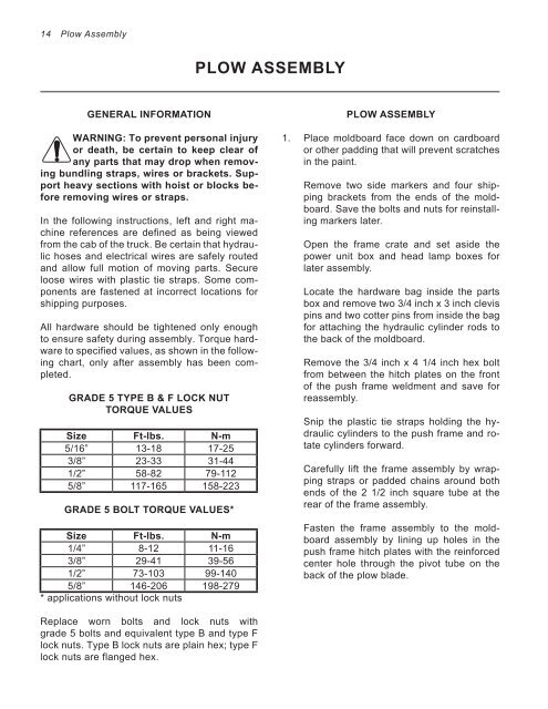
14 Section <strong>Plow</strong> Assembly<br />
GENERAL INFORMATION<br />
WARNING: To prevent personal injury<br />
or death, be certain to keep clear of<br />
any parts that may drop when removing<br />
bundling straps, wires or brackets. Support<br />
heavy sections with hoist or blocks before<br />
removing wires or straps.<br />
In the following instructions, left and right machine<br />
references are defined as being viewed<br />
from the cab of the truck. Be certain that hydraulic<br />
hoses and electrical wires are safely routed<br />
and allow full motion of moving parts. Secure<br />
loose wires with plastic tie straps. Some components<br />
are fastened at incorrect locations for<br />
shipping purposes.<br />
All hardware should be tightened only enough<br />
to ensure safety during assembly. Torque hardware<br />
to specified values, as shown in the following<br />
chart, only after assembly has been completed.<br />
GRADE 5 TYPE B & F LOCK NUT<br />
TORQUE VALUES<br />
Size Ft-lbs. N-m<br />
5/16” 13-18 17-25<br />
3/8” 23-33 31-44<br />
1/2” 58-82 79-112<br />
5/8” 117-165 158-223<br />
GRADE 5 BOLT TORQUE VALUES*<br />
Size Ft-lbs. N-m<br />
1/4” 8-12 11-16<br />
3/8” 29-41 39-56<br />
1/2” 73-103 99-140<br />
5/8” 146-206 198-279<br />
* applications without lock nuts<br />
Replace worn bolts and lock nuts with<br />
grade 5 bolts and equivalent type B and type F<br />
lock nuts. Type B lock nuts are plain hex; type F<br />
lock nuts are flanged hex.<br />
PLOW TITLE ASSEMBLY<br />
PLOW ASSEMBLY<br />
1. Place moldboard face down on cardboard<br />
or other padding that will prevent scratches<br />
in the paint.<br />
Remove two side markers and four shipping<br />
brackets from the ends of the moldboard.<br />
Save the bolts and nuts for reinstalling<br />
markers later.<br />
Open the frame crate and set aside the<br />
power unit box and head lamp boxes for<br />
later assembly.<br />
Locate the hardware bag inside the parts<br />
box and remove two 3/4 inch x 3 inch clevis<br />
pins and two cotter pins from inside the bag<br />
for attaching the hydraulic cylinder rods to<br />
the back of the moldboard.<br />
Remove the 3/4 inch x 4 1/4 inch hex bolt<br />
from between the hitch plates on the front<br />
of the push frame weldment and save for<br />
reassembly.<br />
Snip the plastic tie straps holding the hydraulic<br />
cylinders to the push frame and rotate<br />
cylinders forward.<br />
Carefully lift the frame assembly by wrapping<br />
straps or padded chains around both<br />
ends of the 2 1/2 inch square tube at the<br />
rear of the frame assembly.<br />
Fasten the frame assembly to the moldboard<br />
assembly by lining up holes in the<br />
push frame hitch plates with the reinforced<br />
center hole through the pivot tube on the<br />
back of the plow blade.