Hiniker 700 Manual - Snow Plow Stuff
Hiniker 700 Manual - Snow Plow Stuff
Hiniker 700 Manual - Snow Plow Stuff

Create successful ePaper yourself
Turn your PDF publications into a flip-book with our unique Google optimized e-Paper software.
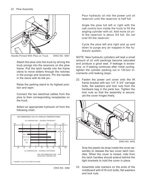
22 <strong>Plow</strong> Assembly<br />
Handle Pinned With <strong>Plow</strong> on Truck DWG NO. 5691<br />
Attach the plow onto the truck by driving the<br />
truck prongs into the receivers on the plow<br />
frame. Pull the latch handle into the frame<br />
clevis to move sliders through the notches<br />
in the prongs and receivers. Pin the handle<br />
in the clevis with its klik pin.<br />
Raise the parking stand to its highest position<br />
and repin.<br />
Connect the two electrical cables from the<br />
plow to their corresponding receptacles on<br />
the truck.<br />
Select an appropriate hydraulic oil from the<br />
following chart.<br />
RECOMMENDED OILS AT VARIOUS TEMPERATURES<br />
OIL TEMPERATURE - - DEGREES FAHRENHEIT<br />
-100 -50 0 50 100 150 200<br />
*<br />
SAE 5<br />
ISO VG 22<br />
SAE 10<br />
ATF<br />
HINIKER "COLD FLOW"<br />
UNIVIS J26<br />
-60 -40 -20 0 20 40 60 80 100<br />
OIL TEMPERATURE - - DEGREES CENTIGRADE<br />
HINIKER "COLD FLOW" MEETS ZFI-5606<br />
*<br />
MAX. RECOMMENDED PUMP<br />
OPERATING TEMPERATURE.<br />
DWG NO. 3066<br />
Pour hydraulic oil into the power unit oil<br />
reservoir until the reservoir is half full.<br />
Angle the plow full left or right with the<br />
cab control box inside the truck to fill the<br />
angling cylinder with oil. Add more oil until<br />
the reservoir is about 3/4 full. Do not<br />
over-fill the reservoir.<br />
Cycle the plow left and right and up and<br />
down to purge any air trapped in the hydraulic<br />
system.<br />
NOTE: New hydraulic cylinders will leak a small<br />
amount of oil until packings become saturated<br />
and produce a good seal. If leakage is excessive,<br />
or if leaking continues after initial cycling,<br />
tighten the cylinder packing nut in 1/8-turn increments<br />
until leaking stops.<br />
22. Fasten the power unit cover onto the lift<br />
frame bracket with two 1/4” X 3/4” carriage<br />
bolts, flat washers and lock nuts from the<br />
hardware bag in the parts box. Tighten the<br />
lock nuts so that the assembly is secure,<br />
yet the cover hinges freely.<br />
DWG NO. 5453<br />
Snip the plastic tie strap inside the cover assembly<br />
to release the two cover latch handles.<br />
When the cover is closed, rods from<br />
the latch handles should extend behind the<br />
light brackets to hold the cover in place.<br />
23. Assemble side markers on the ends of the<br />
moldboard with 5/16 inch bolts, flat washers<br />
and lock nuts.