Hiniker 700 Manual - Snow Plow Stuff
Hiniker 700 Manual - Snow Plow Stuff
Hiniker 700 Manual - Snow Plow Stuff

You also want an ePaper? Increase the reach of your titles
YUMPU automatically turns print PDFs into web optimized ePapers that Google loves.
4 Operating Procedures<br />
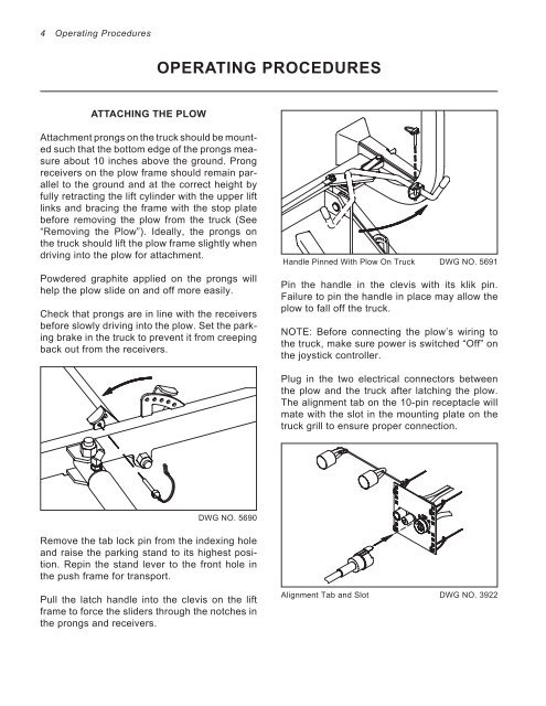
ATTACHING THE PLOW<br />
Attachment prongs on the truck should be mounted<br />
such that the bottom edge of the prongs measure<br />
about 10 inches above the ground. Prong<br />
receivers on the plow frame should remain parallel<br />
to the ground and at the correct height by<br />
fully retracting the lift cylinder with the upper lift<br />
links and bracing the frame with the stop plate<br />
before removing the plow from the truck (See<br />
“Removing the <strong>Plow</strong>”). Ideally, the prongs on<br />
the truck should lift the plow frame slightly when<br />
driving into the plow for attachment.<br />
Powdered graphite applied on the prongs will<br />
help the plow slide on and off more easily.<br />
Check that prongs are in line with the receivers<br />
before slowly driving into the plow. Set the parking<br />
brake in the truck to prevent it from creeping<br />
back out from the receivers.<br />
OPERATING PROCEDURES<br />
DWG NO. 5690<br />
Remove the tab lock pin from the indexing hole<br />
and raise the parking stand to its highest position.<br />
Repin the stand lever to the front hole in<br />
the push frame for transport.<br />
Pull the latch handle into the clevis on the lift<br />
frame to force the sliders through the notches in<br />
the prongs and receivers.<br />
Handle Pinned With <strong>Plow</strong> On Truck DWG NO. 5691<br />
Pin the handle in the clevis with its klik pin.<br />
Failure to pin the handle in place may allow the<br />
plow to fall off the truck.<br />
NOTE: Before connecting the plow’s wiring to<br />
the truck, make sure power is switched “Off” on<br />
the joystick controller.<br />
Plug in the two electrical connectors between<br />
the plow and the truck after latching the plow.<br />
The alignment tab on the 10-pin receptacle will<br />
mate with the slot in the mounting plate on the<br />
truck grill to ensure proper connection.<br />
Alignment Tab and Slot DWG NO. 3922