Hiniker 700 Manual - Snow Plow Stuff
Hiniker 700 Manual - Snow Plow Stuff
Hiniker 700 Manual - Snow Plow Stuff

You also want an ePaper? Increase the reach of your titles
YUMPU automatically turns print PDFs into web optimized ePapers that Google loves.
18 <strong>Plow</strong> Assembly<br />
Attach the tan wire to the spade terminal on<br />
the solenoid above the power unit’s oil reservoir<br />
at location 6. This solenoid extends the<br />
left side of the plow to plow right.<br />
Connect the RH headlamp to the wiring harness<br />
end labeled “PSNGR SIDE” and the<br />
LH headlamp to the end labeled “DRIVER<br />
SIDE”.<br />
Ensure connections are fully mated for proper<br />
sealing. There should be no gaps between<br />
connector halves. Secure these cables to the<br />
frame with plastic ties.<br />
WARNING: Disconnect truck battery before<br />
beginning electrical installation to<br />
avoid shock hazard.<br />
8. The pump solenoid, underhood wiring harness,<br />
power cable and joystick control box<br />
are located in the parts box shipped with the<br />
snowplow frame.<br />
NOTE: Fill electrical connectors with dielectric<br />
grease, and lightly coat ring and spade terminals<br />
before installation to prevent corrosion.<br />
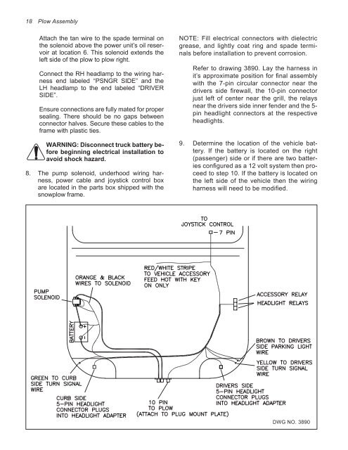
Refer to drawing 3890. Lay the harness in<br />
it’s approximate position for final assembly<br />
with the 7-pin circular connector near the<br />
drivers side firewall, the 10-pin connector<br />
just left of center near the grill, the relays<br />
near the drivers side inner fender and the 5pin<br />
headlight connectors at the respective<br />
headlights.<br />
9. Determine the location of the vehicle battery.<br />
If the battery is located on the right<br />
(passenger) side or if there are two batteries<br />
configured as a 12 volt system then proceed<br />
to step 10. If the battery is located on<br />
the left side of the vehicle then the wiring<br />
harness will need to be modified.<br />
DWG NO. 3890