Hiniker 700 Manual - Snow Plow Stuff
Hiniker 700 Manual - Snow Plow Stuff
Hiniker 700 Manual - Snow Plow Stuff

You also want an ePaper? Increase the reach of your titles
YUMPU automatically turns print PDFs into web optimized ePapers that Google loves.
16 <strong>Plow</strong> Assembly<br />
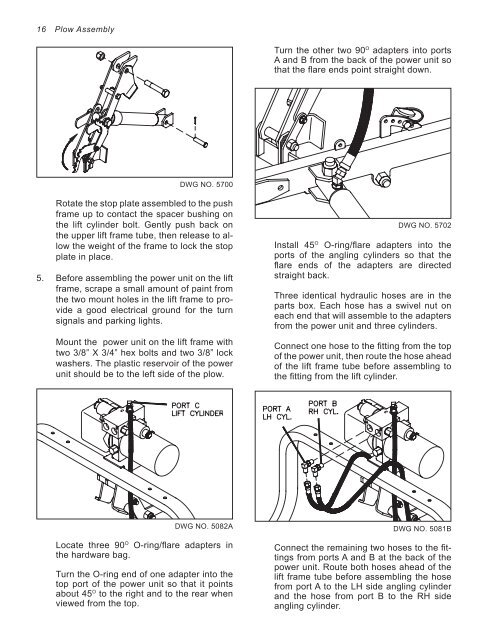
DWG NO. 5<strong>700</strong><br />
Rotate the stop plate assembled to the push<br />
frame up to contact the spacer bushing on<br />
the lift cylinder bolt. Gently push back on<br />
the upper lift frame tube, then release to allow<br />
the weight of the frame to lock the stop<br />
plate in place.<br />
5. Before assembling the power unit on the lift<br />
frame, scrape a small amount of paint from<br />
the two mount holes in the lift frame to provide<br />
a good electrical ground for the turn<br />
signals and parking lights.<br />
Mount the power unit on the lift frame with<br />
two 3/8” X 3/4” hex bolts and two 3/8” lock<br />
washers. The plastic reservoir of the power<br />
unit should be to the left side of the plow.<br />
DWG NO. 5082A<br />
Locate three 90 O O-ring/flare adapters in<br />
the hardware bag.<br />
Turn the O-ring end of one adapter into the<br />
top port of the power unit so that it points<br />
about 45 O to the right and to the rear when<br />
viewed from the top.<br />
Turn the other two 90 O adapters into ports<br />
A and B from the back of the power unit so<br />
that the flare ends point straight down.<br />
DWG NO. 5702<br />
Install 45 O O-ring/flare adapters into the<br />
ports of the angling cylinders so that the<br />
flare ends of the adapters are directed<br />
straight back.<br />
Three identical hydraulic hoses are in the<br />
parts box. Each hose has a swivel nut on<br />
each end that will assemble to the adapters<br />
from the power unit and three cylinders.<br />
Connect one hose to the fitting from the top<br />
of the power unit, then route the hose ahead<br />
of the lift frame tube before assembling to<br />
the fitting from the lift cylinder.<br />
DWG NO. 5081B<br />
Connect the remaining two hoses to the fittings<br />
from ports A and B at the back of the<br />
power unit. Route both hoses ahead of the<br />
lift frame tube before assembling the hose<br />
from port A to the LH side angling cylinder<br />
and the hose from port B to the RH side<br />
angling cylinder.