Hiniker 700 Manual - Snow Plow Stuff
Hiniker 700 Manual - Snow Plow Stuff
Hiniker 700 Manual - Snow Plow Stuff

Create successful ePaper yourself
Turn your PDF publications into a flip-book with our unique Google optimized e-Paper software.
20 <strong>Plow</strong> Assembly<br />
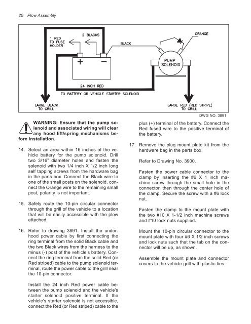
WARNING: Ensure that the pump solenoid<br />
and associated wiring will clear<br />
any hood lift/spring mechanisms before<br />
installation.<br />
14. Select an area within 16 inches of the vehicle<br />
battery for the pump solenoid. Drill<br />
two 3/16” diameter holes and fasten the<br />
solenoid with two 1/4 inch X 1/2 inch long<br />
self tapping screws from the hardware bag<br />
in the parts box. Connect the Black wire to<br />
one of the small posts on the solenoid, connect<br />
the Orange wire to the remaining small<br />
post, polarity is not important.<br />
15. Safely route the 10-pin circular connector<br />
through the grill of the vehicle to a location<br />
that will be easily accessible with the plow<br />
attached.<br />
16. Refer to drawing 3891. Install the underhood<br />
power cable by first connecting the<br />
ring terminal from the solid Black cable and<br />
the two Black wires from the harness to the<br />
minus (-) post of the vehicle’s battery. Connect<br />
the ring terminal from the solid Red (or<br />
Red striped) cable to the pump solenoid terminal,<br />
route the power cable to the grill near<br />
the 10-pin connector.<br />
Install the 24 inch Red power cable between<br />
the pump solenoid and the vehicle’s<br />
starter solenoid positive terminal. If the<br />
vehicle’s starter solenoid is not accessible,<br />
connect the Red (or Red striped) cable to the<br />
plus (+) terminal of the battery. Connect the<br />
Red fused wire to the positive terminal of<br />
the battery.<br />
17. Remove the plug mount plate kit from the<br />
hardware bag in the parts box.<br />
Refer to Drawing No. 3900.<br />
DWG NO. 3891<br />
Fasten the power cable connector to the<br />
clamp by inserting the #6 X 1 inch machine<br />
screw through the small hole in the<br />
connector, then through the center hole of<br />
the clamp. Secure the screw with a #6 lock<br />
nut.<br />
Fasten the clamp to the mount plate with<br />
the two #10 X 1-1/2 inch machine screws<br />
and #10 lock nuts supplied.<br />
Mount the 10-pin circular connector to the<br />
mount plate with four #6 X 1/2 inch screws<br />
and lock nuts such that the tab on the connector<br />
will be up, as shown.<br />
Assemble the mount plate and connector<br />
covers to the vehicle grill with plastic ties.