Hiniker 700 Manual - Snow Plow Stuff
Hiniker 700 Manual - Snow Plow Stuff
Hiniker 700 Manual - Snow Plow Stuff

Create successful ePaper yourself
Turn your PDF publications into a flip-book with our unique Google optimized e-Paper software.
SYSTEM CHECK-OUT<br />
NOTE: The power cable and wiring harness must<br />
be connected between the snowplow and truck to<br />
test the functions of the headlights and power unit.<br />
Vehicle ignition must be switched on.<br />
1. Move the headlight switch on the joystick controller<br />
to the “TRUCK” position and turn on<br />
the vehicle headlights. High and low beams<br />
should operate on the truck.<br />
2. Move the switch to the “PLOW” position.<br />
<strong>Plow</strong> lights should operate in both high and<br />
low beams. Vehicle headlights should be off.<br />
3. Test the parking lights and turn signals. Lights<br />
on the plow and truck should operate at the<br />
same time.<br />
4. In an area clear of bystanders, test joystick<br />
functions by raising and lowering the plow<br />
and angling side to side.<br />
To reverse the angle functions, exchange the<br />
tan and gray wires on the power unit.<br />
Raise and lower functions may be reversed,<br />
as follows.<br />
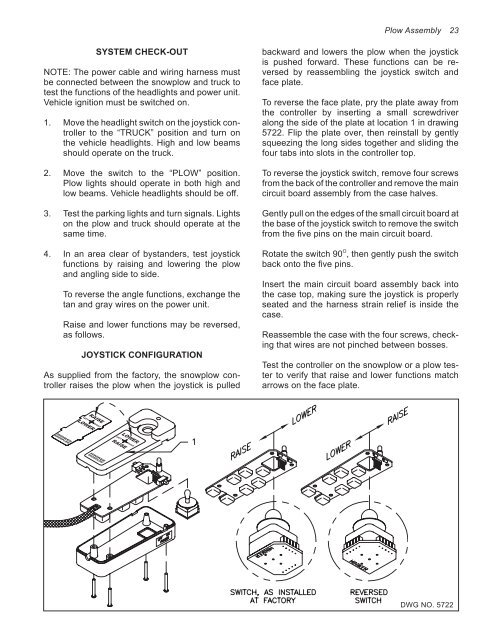
JOYSTICK CONFIGURATION<br />
As supplied from the factory, the snowplow controller<br />
raises the plow when the joystick is pulled<br />
<strong>Plow</strong> Assembly 23<br />
backward and lowers the plow when the joystick<br />
is pushed forward. These functions can be reversed<br />
by reassembling the joystick switch and<br />
face plate.<br />
To reverse the face plate, pry the plate away from<br />
the controller by inserting a small screwdriver<br />
along the side of the plate at location 1 in drawing<br />
5722. Flip the plate over, then reinstall by gently<br />
squeezing the long sides together and sliding the<br />
four tabs into slots in the controller top.<br />
To reverse the joystick switch, remove four screws<br />
from the back of the controller and remove the main<br />
circuit board assembly from the case halves.<br />
Gently pull on the edges of the small circuit board at<br />
the base of the joystick switch to remove the switch<br />
from the five pins on the main circuit board.<br />
Rotate the switch 90 O , then gently push the switch<br />
back onto the five pins.<br />
Insert the main circuit board assembly back into<br />
the case top, making sure the joystick is properly<br />
seated and the harness strain relief is inside the<br />
case.<br />
Reassemble the case with the four screws, checking<br />
that wires are not pinched between bosses.<br />
Test the controller on the snowplow or a plow tester<br />
to verify that raise and lower functions match<br />
arrows on the face plate.<br />
DWG NO. 5722