Split-type air conditioners Mitsubishi Electric MSZ-FH25VE, MSZ ...
Split-type air conditioners Mitsubishi Electric MSZ-FH25VE, MSZ ...
Split-type air conditioners Mitsubishi Electric MSZ-FH25VE, MSZ ...

You also want an ePaper? Increase the reach of your titles
YUMPU automatically turns print PDFs into web optimized ePapers that Google loves.
OPERATING PROCEDURE PHOTOS<br />
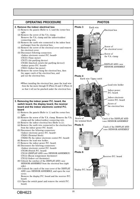
2. Remove the indoor electrical box<br />
(1) Remove the panels (Refer to 1.) and the corner box<br />
right.<br />
(2) Remove the screw of the V.A. clamp.<br />
Remove the V.A. clamp and the indoor/outdoor<br />
connecting wire.<br />
(3) Remove the earth wire connected to the indoor heat<br />
exchanger from the electrical box.<br />
(4) Remove the screw of the electrical cover and remove<br />
the electrical cover.<br />
(5) Disconnect following connectors:<br />
<br />
CN151 (Vane motor)<br />
CN1T1 (Air purifying device)<br />
CN1R1 [Interlock switch (Air purifying device)]<br />
<br />
CN211 (Indoor fan motor)<br />
(6) Remove the screw fixing the electrical box, then<br />
the upper catch of the electrical box, and<br />
pull out the electrical box.<br />
When installing the electrical box, pass the lead wire<br />
from the fan motor through (Photo 9) and (Photo 4)<br />
so that it will not be pinched under the electrical box.<br />
3. Removing the indoor power P.C. board, the<br />
switch board, the display board, the receiver<br />
board and the indoor electronic control P.C.<br />
board<br />
(1) Remove the panels (Refer to 1.) and the corner box<br />
right.<br />
(2) Remove the screw of the V.A. clamp. Remove the V.A.<br />
clamp and the indoor/outdoor connecting wire.<br />
(3) Remove the indoor electrical box (Refer to 2.).<br />
(4) Remove the earth wire connected to the electrical box<br />
from the indoor power P.C. board.<br />
(5) Disconnect the following connectors:<br />
<br />
CN201 (Terminal block)<br />
CN202 (To the indoor electronic control P.C. board)<br />
(6) Remove the lead wire holder.<br />
(7) Remove the indoor power P.C. board.<br />
(8) Disconnect the following connectors:<br />
<br />
CN106 (Switch P.C. board)<br />
CN110 (DISPLAY AND i-see SENSOR ASSEMBLY)<br />
CN111 (Room temperature thermistor)<br />
CN112 (Indoor coil thermistor)<br />
(9) Unhook the catches of the DISPLAY AND i-see<br />
SENSOR ASSEMBLY from the electrical box (right<br />
side).<br />
(10) Unhook the catch of the rear cover of the DISPLAY<br />
AND i-see SENSOR ASSEMBLY, and open the rear<br />
cover.<br />
Remove the display P.C. board and the receiver P.C.<br />
board.<br />
(11) Open the switch panel and remove the switch P.C.<br />
board.<br />
OBH623<br />
35<br />
Photo 3<br />
Photo 4<br />
Earth wire Upper catch<br />
Screw of<br />
the terminal block<br />
Photo 5<br />
Photo 6<br />
Display P.C. board<br />
Earth wire<br />
<strong>Electric</strong>al box<br />
Screw of<br />
the electrical cover<br />
Screw of<br />
the V.A. clamp<br />
DISPLAY AND i-see<br />
SENSOR ASSEMBLY<br />
Lead wire holder<br />
Indoor power<br />
P.C. board<br />
Indoor electronic<br />
control P.C. board<br />
Screw of<br />
the electrical box<br />
Catch of the DISPLAY AND<br />
i-see SENSOR ASSEMBLY<br />
Catch of the DISPLAY AND<br />
i-see SENSOR ASSEMBLY<br />
Receiver P.C. board