Split-type air conditioners Mitsubishi Electric MSZ-FH25VE, MSZ ...
Split-type air conditioners Mitsubishi Electric MSZ-FH25VE, MSZ ...
Split-type air conditioners Mitsubishi Electric MSZ-FH25VE, MSZ ...

You also want an ePaper? Increase the reach of your titles
YUMPU automatically turns print PDFs into web optimized ePapers that Google loves.
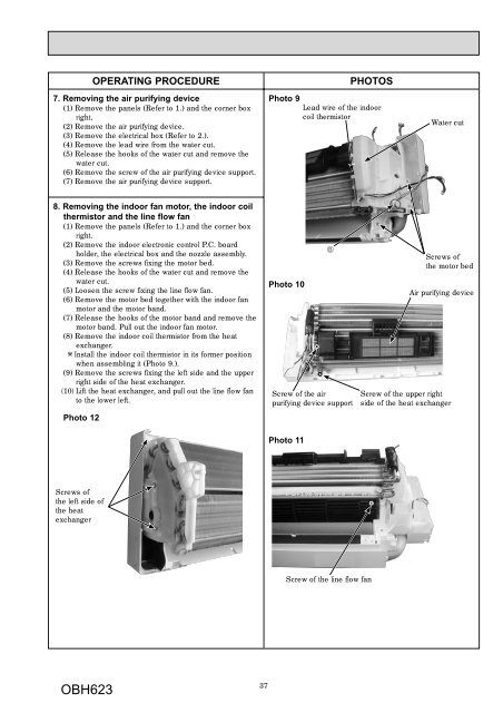
OPERATING PROCEDURE PHOTOS<br />
7. Removing the <strong>air</strong> purifying device<br />
(1) Remove the panels (Refer to 1.) and the corner box<br />
right.<br />
(2) Remove the <strong>air</strong> purifying device.<br />
(3) Remove the electrical box (Refer to 2.).<br />
(4) Remove the lead wire from the water cut.<br />
(5) Release the hooks of the water cut and remove the<br />
water cut.<br />
(6) Remove the screw of the <strong>air</strong> purifying device support.<br />
(7) Remove the <strong>air</strong> purifying device support.<br />
8. Removing the indoor fan motor, the indoor coil<br />
thermistor and the line flow fan<br />
(1) Remove the panels (Refer to 1.) and the corner box<br />
right.<br />
(2) Remove the indoor electronic control P.C. board<br />
holder, the electrical box and the nozzle assembly.<br />
(3) Remove the screws fixing the motor bed.<br />
(4) Release the hooks of the water cut and remove the<br />
water cut.<br />
(5) Loosen the screw fixing the line flow fan.<br />
(6) Remove the motor bed together with the indoor fan<br />
motor and the motor band.<br />
(7) Release the hooks of the motor band and remove the<br />
motor band. Pull out the indoor fan motor.<br />
(8) Remove the indoor coil thermistor from the heat<br />
exchanger.<br />
Install the indoor coil thermistor in its former position<br />
when assembling it (Photo 9.).<br />
(9) Remove the screws fixing the left side and the upper<br />
right side of the heat exchanger.<br />
(10) Lift the heat exchanger, and pull out the line flow fan<br />
to the lower left.<br />
Photo 12<br />
Screws of<br />
the left side of<br />
the heat<br />
exchanger<br />
OBH623<br />
37<br />
Photo 9<br />
Photo 10<br />
Screw of the <strong>air</strong><br />
purifying device support<br />
Photo 11<br />
Lead wire of the indoor<br />
coil thermistor<br />
Screw of the line flow fan<br />
Water cut<br />
Screws of<br />
the motor bed<br />
Air purifying device<br />
Screw of the upper right<br />
side of the heat exchanger