Pathfinder instructions - The WoodRat
Pathfinder instructions - The WoodRat
Pathfinder instructions - The WoodRat

Create successful ePaper yourself
Turn your PDF publications into a flip-book with our unique Google optimized e-Paper software.
THE <strong>WoodRat</strong><br />
PATHFINDER<br />
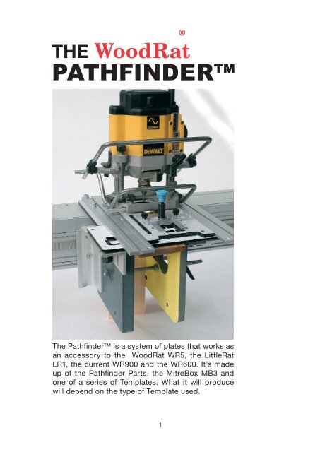
<strong>The</strong> <strong>Pathfinder</strong> is a system of plates that works as<br />
an accessory to the <strong>WoodRat</strong> WR5, the LittleRat<br />
LR1, the current WR900 and the WR600. It’s made<br />
up of the <strong>Pathfinder</strong> Parts, the MitreBox MB3 and<br />
one of a series of Templates. What it will produce<br />
will depend on the type of Template used.<br />
1<br />
®
Contents<br />
Introduction<br />
Before you begin<br />
parts not included in the <strong>Pathfinder</strong><br />
<strong>The</strong> <strong>Pathfinder</strong><br />
MitreBox MB3<br />
<strong>Pathfinder</strong> Parts<br />
<strong>The</strong> Templates<br />
Tenons<br />
Set up for Tenons<br />
Making the tenon<br />
Making the mortise<br />
Dovetails<br />
Set-up for Dovetails<br />
Grooving<br />
Symmetrical Dovetails:<br />
Run of Pins<br />
the Tail sockets<br />
Test Pins<br />
Asymmetrical Dovetails<br />
Half Blind or Lapped Dovetails<br />
Set-up<br />
Making classic drawers<br />
Tail sockets<br />
Test pins<br />
Run of Pins<br />
<strong>The</strong> Blank Template<br />
2
Introduction to the <strong>Pathfinder</strong><br />
A few years ago certain companies began producing<br />
Mortise and Tenon jigs to simplify the process<br />
of making mortise and tenon joints and at the same<br />
time to solve the problem inherent in routing with<br />
a round bit, which is that it makes round ended<br />
mortises – the proverbial square peg in the round<br />
hole.<br />
This niggled at us too, but having the <strong>WoodRat</strong> as<br />
a starting point, the direction it took us surprised<br />
us by producing not only a foolproof way of cracking<br />
out tenons, but it also led on to a whole variety<br />
of joints – tenons, through dovetails and half-blind<br />
dovetails and all sorts of shapes and so on, each<br />
ve Moreover it was all based on familiar <strong>WoodRat</strong><br />
technology.<br />
<strong>The</strong> one thing that it did not produce was an easy<br />
way of making mortises. But then mortises are traditionally<br />
made in a very separate way from tenons,<br />
and our solution for them, the MR4 Mortise Rail, has<br />
also led us to a lot of other ways of making many<br />
interesting things.<br />
I hope you get great pleasure from the <strong>Pathfinder</strong> as<br />
well as finding it useful. It is still in the experimental<br />
stage and the invitation is there for you to join us<br />
in discovering innovative ways to use it. Keep in<br />
touch.<br />
3
<strong>The</strong> WR600, WR5 and the WR900<br />
make a suitable platform for the <strong>Pathfinder</strong>. Use your<br />
Alu GuideRails and Router Plate RP3 (with new hole<br />
configuration) and raising plate if necesary. Older<br />
GuideRails need an extra counterbored M4 hole, and<br />
you will need to drill and tap older Router Plates or buy<br />
a new RP3 Router Plate. <strong>The</strong> new Ali Fences are ideal for<br />
firming up the MitreBox.<br />
6541 Starknob<br />
Halfplate<br />
3141 Guiderail Left<br />
4262<br />
Aluminium<br />
Fence<br />
Attaches to the Left<br />
hand Cheek to secure<br />
the MitreBox.<br />
5616 M4 16<br />
M6 Locking key x 2<br />
Aluminum Bracket<br />
5684 4M Nut<br />
3. <strong>Pathfinder</strong><br />
Templates<br />
<strong>The</strong>re are a growing selection<br />
of Templates for a wide variety<br />
of tasks. <strong>The</strong>y can be made to<br />
order.<br />
6461 Routerplate<br />
6421 Lobed Washer<br />
Left-hand Cheek<br />
Drop Pin<br />
4<br />
3142 Guiderail Right<br />
M6 Locking screw x2<br />
PARTS LIST<br />
PARTS FOR THE PATHFINDER Pf1<br />
<strong>The</strong> <strong>Pathfinder</strong> uses the <strong>WoodRat</strong> MitreBox MB3 to hold the workpieces plus several<br />
new components (<strong>Pathfinder</strong> Parts) that enable it to track the pathways in the<br />
Templates. Templates come in a variety of patterns depending on the joint or<br />
3316 Raising Plate<br />
Use your Raising<br />
Plates if needed for<br />
extra depth for<br />
tenons<br />
M8 50<br />
6mm Hex key<br />
component to be made.<br />
M8 nut<br />
M8 Self-tapping inserts<br />
Tenon Template<br />
Through DovetailsTemplate<br />
1. <strong>Pathfinder</strong> Parts:<br />
Half plate<br />
Drop-Pin Plate<br />
Drop pin<br />
Bracket<br />
M6 Locking screws x4<br />
M8 20 x2<br />
2. MiterBox MB3<br />
Left hand Cheek<br />
Right hand Cheek<br />
Drop-Pin Plate<br />
M4 16 x 4<br />
M4 nuts x 4<br />
Rod Clamp components<br />
5424 Locking Lever<br />
5421 Lobed Washer<br />
M10 nuts x 4<br />
M10 washers x 5<br />
300mm threaded Rod x 2<br />
Right-hand M8 self tapping inserts x 2<br />
M8 nut<br />
5512 Rubber washer x 2<br />
Rod Lock<br />
Half-blind Dovetail Template<br />
5424 Locking Lever<br />
Spreader Rod<br />
Although we will try to advertise any item changes in good time, in the interest of continuous improvement in the quality and value of our products,<br />
<strong>WoodRat</strong> reserve the right to change components in colour, function and material without prior warning.
5616 M4 16<br />
5684 4M Nut<br />
<strong>The</strong> aluminium fence has two tee-slots<br />
that will hold the left-hand cheek firm<br />
and square to the sliding bar.<br />
<strong>The</strong> guiderails have an extra<br />
pair of counterbored<br />
4mm holes to take an<br />
M410 to attach it to the<br />
half-plate<br />
<strong>The</strong> router plate has<br />
three pairs of M6 holes<br />
to take the Drop-pin<br />
plate<br />
5<br />
Before you begin<br />
Some parts are not part of the <strong>Pathfinder</strong>, as they are<br />
now a standard part of the <strong>WoodRat</strong> kit. <strong>The</strong>y can be bought<br />
separately from your <strong>WoodRat</strong> dealer if you need them.<br />
1. <strong>The</strong> Aluminium Fences<br />
We have recently introduced new Aluminium Fences to replace<br />
the earlier moulded nylon ones. Firm and square enough for<br />
ordinary purposes, they are well worth having for <strong>Pathfinder</strong><br />
work as they allow you firmly to attach the Left hand Cheek<br />
to the Sliding Bar to form the MitreBox MB3.<br />
<strong>The</strong> Fence has two tee slots in it so that the Left hand Cheek<br />
can be bolted to it with four M4 16 screws to hold it firm and<br />
exactly square. A third tee-slot behind the finger grip takes<br />
the Big Cursor. This is not generally of use with the templates<br />
which have their own way of registering where the cuts are<br />
to come.<br />
<strong>The</strong> ali fences come with wooden faces that allow you to add<br />
sandpaper to stop the wood slipping. Do not sandpaper the<br />
aluminium Fence direct.<br />
But now take off the Ali Fence. Take off the Plywood Face<br />
and store it, before you put the Left Cheek into the tee-slots<br />
of the Sliding Bar.<br />
<strong>The</strong> M4 16 screws go into cheek. <strong>The</strong> nuts go on loosely and<br />
the Cheek is slid into the tee-slot of the Sliding Bar <strong>The</strong> Fence<br />
is slid upwards onto the nuts before being screwed to the Bar,<br />
and the M4 screws tightened.<br />
2. Ali GuideRails:<br />
You will need your <strong>WoodRat</strong> or LittleRat GuideRails. Note<br />
that there is an extra M4 threaded hole in the HalfPlate. If your<br />
GuideRails do not have corresponding holes, you will need<br />
to drill them 4mm counterbored to 8mm to house the head<br />
of the M4 10 screw. <strong>The</strong>se extra screws stop the routerplate<br />
from twisting the rails out of true, and hold everything firm on<br />
the Half Plate.<br />
3. <strong>The</strong> New RP3 RouterPlate has 6 x 6mm tapped holes that<br />
take the locking keys for the Drop-pin plate. If you have an old<br />
routerplate and you are not confident at drilling and tapping,<br />
it might be best to buy a new RP3.<br />
Otherwise the RP3 is similar to the RP2 routerplate except<br />
that is has two extra tapped M8 holes for attaching fences<br />
of different types to the underside of the Plate. This allows<br />
you to use the Router for freehand work without taking the<br />
router off the Plate. You have the advantage of a larger base<br />
for the router, plus the ability to make a fence that suits the<br />
job in hand: 8mm deep for running against an 8mm straight<br />
edge laid across a sheet of material or, for example, deeper<br />
for moulding the edge of a table, for example.
Setting up the <strong>Pathfinder</strong><br />
<strong>The</strong> <strong>Pathfinder</strong> Pf1 comes in three parts. <strong>The</strong>y can be<br />
bought separately, or bundled together. If you have an<br />
MB3 MitreBox you will need only the <strong>Pathfinder</strong> Parts and<br />
a Template to begin wo.<br />
Most of the actions and techniques such as the tracking, holding<br />
wood in the CamLocks, using the raising plates, plunging<br />
and depthing the router, will be familiar to anyone who knows<br />
the <strong>WoodRat</strong>, but if you are new to it, you will find it helpful to<br />
read the Manual that comes with your basic machine, and put<br />
in some practice.<br />
<strong>The</strong> workings of the <strong>Pathfinder</strong> itself are mostly self-evident. Tenons<br />
are a breeze and Through Dovetails are not too difficult, but<br />
the Half-Blinds are so quick in operation that it is well worth the<br />
initial mental effort. It’s even worth following the <strong>instructions</strong>.<br />
1. <strong>The</strong> <strong>Pathfinder</strong> Parts<br />
<strong>The</strong> first part of the <strong>Pathfinder</strong> is what we call the ‘<strong>Pathfinder</strong><br />
Parts’.<br />
<strong>The</strong>se need to work with the MB3 MitreBox to complete the Pf1<br />
<strong>Pathfinder</strong>.<br />
1.1. <strong>The</strong> Halfplate<br />
<strong>The</strong> BasePlate of the <strong>WoodRat</strong> is replaced for <strong>Pathfinder</strong> work<br />
by the HalfPlate. <strong>The</strong> front edge of the Halfplate has a groove<br />
that takes the tongue cut into edge of all the Templates which<br />
interlock with it and can slide east/west with no north/south<br />
movement. Use the M8 25 screws that come as standard with<br />
the <strong>WoodRat</strong> kit.<br />
Raising Plates<br />
Loosen the HalfPlate and add Raising Plates under it as necessary<br />
to give more depth of cut. <strong>The</strong> Raising Plate (or plates) come<br />
as standard with the <strong>WoodRat</strong> kit, to allow a greater depth of<br />
cut when needed for tenons. It uses the M8 25 or M8 50 screws<br />
which come standard with the <strong>WoodRat</strong> kit. Plus the M4 10<br />
screws to hold the GuideRail to the Halfplate.<br />
1.2 Drop-pin Plate<br />
<strong>The</strong> new RP3 RouterPlate is largely the same as the older Plate<br />
but is modified to take the Drop Pin Plate. This fits into its tee slot<br />
and is held either side by M6 10 Locking Keys. Its position can<br />
be adjusted north/south in the RouterPlate, and it can be locked<br />
down. It determines the distance between the Pin as it wanders<br />
around the template and the Bit as it cuts the workpiece.<br />
It governs the distance between the Bit and Pin.<br />
<strong>The</strong> Drop Pin<br />
<strong>The</strong> Drop Pin has a sprung pin that can be raised and kept up,<br />
or dropped down to engage with the grooves, islands, wedges<br />
and pathways in the Template. So, as the Template and with it<br />
the Workpiece is tracked west/east, the Pin, and with it the Bit,<br />
can go north/south.<br />
So in effect, the pin finds its way around any useful kind of Pathway<br />
cut in the template allowing the bit to travel a similar kind of<br />
pathway in the workpiece; hence the name <strong>Pathfinder</strong>.<br />
6<br />
M6 Locking Key<br />
Drop Pin<br />
Make sure that you have the<br />
4mm counterbored hole here.<br />
M6 Locking Key<br />
Drop Pin Plate
M8 50<br />
6mm Hex key<br />
M8 nut<br />
M8 Self-tapping inserts<br />
<strong>The</strong> cheeks are made of HDF which<br />
is brittle, but can be drilled, worked<br />
and added to.<br />
<strong>The</strong> <strong>WoodRat</strong> manual gives a lot of<br />
hints on how to use the MitreBox<br />
for many other uses than simply<br />
working at 45° angles<br />
1.3. <strong>The</strong> Bracket<br />
This attaches to the Left Hand Cheek of the MitreBox MB3. <strong>The</strong> Cheek<br />
must be fitted with two M8 brass inserts which take the two M8 25’s.<br />
<strong>The</strong>y go through the two vertical slots, allowing the Bracket, and the<br />
Template with it, to be raised up under the Guiderails when the Raising<br />
Plate is in use.<br />
<strong>The</strong> Bracket also has two open slots which take the M6 Locking Keys<br />
screwed into the Template. <strong>The</strong> keys, when loose, can slide in the<br />
slots and can be positioned and tightened up, so that the Template,<br />
sliding in the groove in the HalfPlate may be tracked east/west under<br />
the RouterPlate,<br />
This east/west adjustment of Template on the Bracket governs the<br />
way the joints are laid onto the workpiece.<br />
1.4. <strong>The</strong> Brass Inserts<br />
<strong>The</strong>re are two brass inserts that need to be wound into the two holes<br />
at the top of the left Cheek. they can be driven in with a large screwdriver,<br />
but it is simpler to use a long M8 socket head cap screw. If<br />
you just use the screw, put the insert on it, and wind it in with the hex<br />
key, you might find that the insert jams on the screw and unscrews<br />
when you wind the screw out again. A nut on the screw, then the insert,<br />
before winding it in will prevent this happening. Make sure that<br />
it winds in straight.<br />
Recently we have been placing the inserts for you.<br />
2. <strong>The</strong> MitreBox MB3<br />
This is the second part of the <strong>Pathfinder</strong><br />
<strong>The</strong>re are differences between the setups needed for the different<br />
Templates, but this is the basic system:<br />
2.1. <strong>The</strong> Left Cheek<br />
of the MB3 attaches to the Ali Fence. It is placed first with its ‘toes’ in<br />
the big tee-slot of the Sliding Bar. <strong>The</strong> four M4 16 screws are put into<br />
the four counter-bored holes in the Cheek with the M4 nuts placed<br />
loosely: the Fence is slid upward taking the nuts into the two tee-slots<br />
and the Fence is screwed to the Sliding Bar with the M8 countersunk<br />
screws in the usual way. Before the four M4 16’s are tightened fully,<br />
pull the Fence forward and push the Cheek gently but firmly against<br />
the Machine Face to take out any slack in the Bar.<br />
For most work with the <strong>Pathfinder</strong> you only need the Left Cheek. When<br />
you do need the Right Cheek, you’ll need the RodLock to hold it all<br />
firmly, as a Box.<br />
Set up the parts of the <strong>Pathfinder</strong> as the diagram. For the <strong>WoodRat</strong>,<br />
use the right-hand CamLock. <strong>The</strong> LR1 and WR600 have only one gate,<br />
but the process is exactly the same.<br />
Some people buy an extra fence so that it can be kept permanently<br />
with the left cheek.<br />
2.2. <strong>The</strong> Right Cheek<br />
<strong>The</strong> right-hand cheek is the thinner one. You’ll not<br />
need it for the tenons or for through dovetails: only<br />
later, for half-blind dovetails, and for mitred work<br />
generally.<br />
7
2.3. <strong>The</strong> Rod Lock<br />
<strong>The</strong> threaded rods and how they are used is covered in a later<br />
section on Half-blind Dovetails.<br />
3. <strong>The</strong> Templates<br />
<strong>The</strong> third essential part of the <strong>Pathfinder</strong> is the Template.<br />
<strong>The</strong>se plates have a shaped long edge that interlocks<br />
with the Half-plate. <strong>The</strong>y each have a way<br />
of being screwed to slots in the Bracket, using<br />
M6 Locking Keys from below.<br />
3.1. <strong>The</strong> Tenon Template<br />
works with straight bits: 8mm 10mm and Half<br />
inch. It will make Twin and Single and Double<br />
Twin tenons in a range of lengths. <strong>The</strong> tenons<br />
can be made round or square ended. It<br />
will also make dowels. This technique<br />
complements mortises made in the MR4<br />
Mortice Rail.<br />
3.2. Through Dovetail Plates<br />
Each plate makes classic through dovetails<br />
of fixed pitch but for a range of sizes<br />
of dovetail bit.<br />
3.3. <strong>The</strong> Half-Blind Dovetail Template<br />
is the fastest way to joint drawers. Each Template<br />
has two different pitches for the same size<br />
of <strong>WoodRat</strong> dovetail bit. This Template and the<br />
correct bit have to be used together.<br />
3.4. <strong>The</strong>re is also a Blank Template<br />
You can cut out any shape in 3mm sheet acrylic and make<br />
from it any wooden shape you wish. Any kind of shape that<br />
can be devised in the template can cut a similar shape in<br />
the wood.<br />
<strong>The</strong> pathway might make stars, animal shapes for a Noah’s<br />
Ark, or a line of multiple Santa Clauses. More practically,<br />
circles or squares will make inter-locking lids and boxes. You<br />
will need to experiment with different sized bits and different<br />
thicknesses of wall for the drop-pin to run against.<br />
6421 Lobed Washer<br />
8<br />
Rod Lock<br />
5424 Locking Lever<br />
Spreader Rod
Simple strips of sandpaper<br />
are quite adequate to hold<br />
the wood vertical, horizontal<br />
and at angles.<br />
9<br />
Working with the <strong>Pathfinder</strong><br />
Preparation<br />
However well the <strong>WoodRat</strong> parts are finished, your <strong>Pathfinder</strong><br />
parts, plates and sliding bar, will need to be thoroughly<br />
waxed and polished before work can begin. <strong>The</strong><br />
whole mechanism must run like silk.<br />
When the Template is added it needs to be locked in so<br />
that there is the minimum of movement when the pin is<br />
dropped, for instance, in the centre hole in the tenon<br />
template. You will need to check that the router plate<br />
runs smoothly fore and back and that there is no sideways<br />
slap between plate and guiderails.<br />
It might be necessary to take everything apart to ensure<br />
that all sliding parts are as slick as can be.<br />
Holding the work<br />
Locking a rail in the Camlock is the same as for general Wood-<br />
Rat work, you need to pull with your fingers and push with<br />
your thumb as you clamp in the work, to take out any slack in<br />
the sliding bar, and make sure it’s firmly seated. Bring up the<br />
Camlock, and lock in a scrap rail, making sure that the Bar<br />
tracks nicely west/east....<br />
and that the Router runs smoothly north/south: if necessary,<br />
wax all rubbing surfaces. Take out any lateral movement between<br />
GuideRails and RouterPlate.<br />
Sandpaper your faces:<br />
to give some friction to the inner faces of the Cheeks, we recommend<br />
that you sandpaper the faces. Use impact adhesive,<br />
pasted on both surfaces and allowed to dry before bonding<br />
the two surfaces together: this makes for very durable non-slip<br />
surfaces to hold the work. Alternatively use a rubber cement<br />
(Copydex) that does not last for ever, but which can be peeled<br />
off and replaced more easily.<br />
Use around a 120 grit and trim round the Cheeks with a sharp<br />
knife.<br />
Dust Extraction<br />
Ensure that you have good strong dust extraction, particularly<br />
for the harmful fine dust.<br />
Note: LR1 LittleRat users can use the new RP3 RouterPlate for<br />
all normal LittleRat work except variably spaced half-blind dovetails.<br />
Either revert to your LittleRat router plate or invest in a HalfBlind<br />
Dovetail Template and use the <strong>Pathfinder</strong>.<br />
<strong>The</strong> Bracket<br />
<strong>The</strong> Alu bracket is set by screwing two M8 20 screws into<br />
the brass inserts. Do not tighten the screws you have set the<br />
Template, and raised it up under the guiderails. <strong>The</strong> slots allow<br />
you to raise the Template when Raising Plates are in use.<br />
Check your router for run out. Make a test cut with a straight<br />
bit in some hardwood scrap to check that a socket made<br />
with a 10mm bit is indeed cutting 10 mm wide. If it is cutting<br />
large, check that there is no slack between the guiderails and<br />
routerplate.<br />
If there is still serious run-out and you are using a quick release<br />
chuck, re-insert your original collet and try again. If there is still<br />
run-out, you have a problem with the router. if not, you have a<br />
problem with the quick release chuck. In which case undo the<br />
chuck and turn it a quarter turn and retighten, and test again. This<br />
may improve the seating. If you cannot improve it, let us know.
A collection of tenons made during the experimental<br />
stages of developing the <strong>Pathfinder</strong>.<br />
<strong>The</strong> collection comprises tenons double tenons and dowels and stars made<br />
with a star shape placed in the blank template<br />
10
Using the Tenon Template<br />
Aluminium<br />
guiderails allow the<br />
router to cut the<br />
work on the axis<br />
north/south<br />
<strong>The</strong> half-plate<br />
holds the<br />
Template as it<br />
slides East/West<br />
Bracket is raised so as<br />
to lift the Template up<br />
under the half-plate<br />
<strong>Pathfinder</strong> Tenons – either single or double – are very straightforward. <strong>The</strong> Template<br />
forms not only round ended tenons of various useful sizes, but also dowels at the extreme<br />
left, and a long tenon that can be used for square ended tenons with haunches at<br />
the extreme right of the plate.<br />
Introducing the Tenon Template.<br />
Polish all sliding surfaces so that everything slides easily when<br />
it should, or locks down firmly when it needs to be firm.<br />
Use the left-hand Cheek only. Place one 25mm/1” or two<br />
12mm 1 /2” Raising Plates under the HalfPlate to give you up<br />
to 50mm/2” depth of cut.<br />
<strong>The</strong> Tenon Template has four lines of Islands – in two pairs of<br />
two, each pair starts with circles and ends with long islands.<br />
<strong>The</strong> top line of each pair is for single tenons; twins are made<br />
using both lines.<br />
<strong>The</strong> tenon Template is designed to make tenons that fit mortises<br />
cut by an 8mm, 10mm or a half inch (12.7mm) bit.<br />
11<br />
Left Cheek of the MB3<br />
mitreBox only is used<br />
for makingTenons<br />
<strong>The</strong> Drop-pin in the<br />
Drop-pin plate follows<br />
around the ‘islands’ in<br />
the Template, as the<br />
Bit cuts the<br />
workpiece under<br />
the plate<br />
<strong>The</strong> Tenon template allows the<br />
work to move east/west depending<br />
on the drop-pin controling the<br />
position of the router. With this<br />
Template it makes round ended<br />
tenons – double and twin, and also<br />
dowels.<br />
Look at the rail end, and check it against the islands to decide<br />
whether you need twin or single, or single or double tenons.<br />
Or double twins.<br />
Decide which bit you are going to use for your mortises, and<br />
therefore the tenon size. <strong>The</strong> Template will make your tenons<br />
either 8mm, 10mm or half inch, so your mortises will be either<br />
8, 10 or half inch.<br />
As the Template is designed to make the tenon fit the mortise,<br />
you can make the tenons first. This has advantages over<br />
making the mortises first, as we shall see.<br />
Decide how long you need your tenon by matching the rail<br />
end with an Island. At it’s simplest a single tenon will go in<br />
the centre of the rail, but you can place it where needed. A
twin tenon will have the socket between the tenons<br />
placed central. To get the length of tenon, place your<br />
work-piece against the islands to check which to use,<br />
but note that the actual size of the tenon is 2mm or<br />
so inside the island. Put a pencil mark on the Island<br />
you are using so you can find it when it’s under the<br />
plate.<br />
With the upper pair of lines, use an 8mm<br />
straight bit to make a 10mm tenon,<br />
or a 10mm bit, to make an 8mm tenon.<br />
With the lower pair of lines, use a 10mm<br />
bit to cut a 1/2” (12.7mm) tenon,<br />
or a 1/2” (12.7mm) bit to cut a 10mm tenon.<br />
Select a bit to make the tenon you want and place<br />
it in the collet.<br />
Screw the Template to the Bracket loosely, and track<br />
it under the Router Plate, threading the Template over<br />
the supporting groove in the HalfPlate and under the<br />
GuideRails. Lift the Template and Bracket gently up<br />
under the GuideRails and tighten the M8 20 screws<br />
on the Bracket. It should track west/east freely, so<br />
make sure that it does.<br />
<strong>The</strong> Drop-pin Plate<br />
<strong>The</strong> Drop Pin screws into the Drop Pin Plate.<br />
Place the DropPin Plate in the RouterPlate: screw in<br />
a 6mm Locking Key loosely either side. See how the<br />
plate will slide north/south when loose, and lock down<br />
when the screws are tightened. By placing the screws<br />
in one of the three pairs of holes, the pin can cover a<br />
distance fore and back across the Template.<br />
Lift the Pin, making sure that it moves freely over the<br />
template. Note that the cutter is free to cut at random<br />
into any work-piece placed in the CamLock when the<br />
Pin is raised.<br />
So raise the Bit. Get into the habit of raising the bit after each<br />
run of cuts.<br />
Drop the Pin and see how its travel is limited by the Islands of<br />
the Template. Track the Crank Handle as you move the router<br />
forward and back and see practice running around the Islands<br />
in the Template.<br />
Marking the rail end<br />
Mark up the end of the rail with two centre lines, the east/<br />
west (x-axis) and the north/south (y-axis) line... and cam it<br />
in place.<br />
Note that there‘s no need to find the exact centre, as you can<br />
make two lines, one from each face, rather than fuss about<br />
finding the centre. Set your cutting gauge to roughly a half<br />
and make two lines one from each face. One blade of the Bit<br />
will later line up with one, and the other blade with the other<br />
cut line, and the Bit will be exactly centered. If you have sharp<br />
eyes or alternatively good 3 diopter specs, this method will be<br />
extremely accurate.<br />
Note that the centre of the tenon might not need to be central<br />
to the rail. It will depend on your design.<br />
Locating the Template<br />
Place the two M6 Locking Keys, in the correct holes for the<br />
required Island. Note that the locking key holes are found two<br />
places away to the left of the island you are using (the one you<br />
marked up earlier).<br />
Slide the Template so that the Locking Keys engage in the open<br />
Bracket slots. Tighten them temporarily, and track the Bracket<br />
and Template under the GuideRails and Router Plate.<br />
Your marked-up Island will appear under the DropPin as the<br />
crossed lines on the Rail end appear under the bit, but not<br />
yet lined up. Now locate the Drop Pin in the hole in the Tenon<br />
Island (the exact center of the Island).<br />
12<br />
north/south<br />
east/west line<br />
Cross hairs find the<br />
centre of the rail end<br />
<strong>The</strong> Bit finds the<br />
middle of the rail,<br />
while the Pin finds<br />
the centre of the<br />
Island<br />
Two lines give the<br />
centre line when<br />
using a bit with<br />
two blades<br />
When the Pin is<br />
in the centre of<br />
the Island you<br />
can line up both<br />
axes on the cross<br />
hairs.
<strong>The</strong> half-plate<br />
which is screwed<br />
to the Channel<br />
engages with the<br />
Template, which<br />
moves with the<br />
workpiece.<br />
<strong>The</strong> Pin goes into the hole in the<br />
Island, the Template’s Locking<br />
Keys are slackened. <strong>The</strong> Bit lines<br />
up on the centre line of the rail<br />
end, and the Keys tightened.<br />
13<br />
Slacken the Template’s M6 Locking Keys, and track the rail,<br />
to centre the blades of the bit (set north/south) to align with<br />
the y-axis lines. Tighten the screws. This positions the tenon<br />
east/west on the rail end.<br />
2. Locating the DropPin Plate<br />
Loosen the DropPin Plate on the RouterPlate and move the<br />
Bit so that the blades line up with the horizontal lines on the<br />
rail end, then tighten the thumbscrews. You’re now aligned<br />
north/south (on the x-axis).<br />
<strong>The</strong> pin is still in the hole, so raise the pin.<br />
This frees the router bit, so un-plunge the router at the same<br />
time.<br />
Make it a habit: raise the router and the pin every time you<br />
finish a joint. <strong>The</strong>n you can’t harm anything.<br />
<strong>The</strong> Z-axis<br />
<strong>The</strong> Channel<br />
GuideRails<br />
<strong>The</strong> Template slides east/west in the groove in the Half-Plate. <strong>The</strong> Drop Pin in its plate controls the action<br />
north/south of the router. In effect you run round the template Islands with the Drop Pin which describes<br />
the shape of the island on the tail end.<br />
Router Plate with Drop-Pin Plate with<br />
Pin engaging in the Template. Lift the<br />
Pin and the router is free<br />
<strong>The</strong> Tenon Template<br />
Make sure you have enough depth of cut. Slide in a raising<br />
plate as necessary.<br />
Your rail will be marked out with the size between the stiles<br />
and cut with adequate length of tenon at either end. So when<br />
you place the rail beneath the plate you will be able to drop<br />
the bit to the inside line of the door or frame. No zeroing the<br />
bit this time.
If you work from an exact centre line, both your tenons will be<br />
of equal length. <strong>The</strong>y may be too long but you can cut them<br />
down later. If too short, you will need longer rails.<br />
Cutting the Tenon<br />
Drop the bit and with the pin up and the bit down, you’re set<br />
to go. You can now cut anywhere, so be careful.<br />
Cut clockwise all around the rail to clean the shoulder of the<br />
tenon. This without the pin hitting the Island. It is just to skim<br />
the outside of the rail to make a clean shoulder all round.<br />
Now drop the Pin and continue to cut the tenon clockwise. <strong>The</strong><br />
Pin wheel will now hit and run around the Island and describe<br />
the outline of the tenon on the rail end at the same time. Go<br />
gently and take your time.<br />
With a little practice, you’ll find the best track to take, and<br />
will develop your own techniques for maximum speed and a<br />
perfect finish.<br />
Go for finish first and speed later.<br />
Nothing much can go wrong. If you find that the cutter is<br />
cutting into the tenon, check that your locking pins are reasonably<br />
tight: the plate or the template can come loose, but<br />
shouldn’t.<br />
Be sure you are aware when the Bit is up and harmless, and<br />
when down and meaning business, and when the Pin is up<br />
and the bit not controlled by the template and when down and<br />
only cutting where you need it.<br />
Repeat for the tenon on the other end by cart-wheeling the<br />
rail (the face side kept always against the machine face)... and<br />
then the next, and so on.<br />
Twin Tenons<br />
Twins are made by running around the two twin islands together<br />
on the one rail. <strong>The</strong> centering method is a little bit<br />
different:<br />
Slacken the DropPin Plate Locking Screws. <strong>The</strong> y-axis alignment<br />
is done with the pin in the center hole as before.<br />
But the centreline of the joint north/south is given by placing<br />
the pin central between the Islands, and aligning the blades<br />
of the bit on the y-axis lines.<br />
14<br />
Now the Pin Plate’s Locking Keys<br />
are slackened. <strong>The</strong> Pin stays in<br />
the hole, but the Bit is brought<br />
forward to line up with the horizontal<br />
line.<br />
<strong>The</strong> bit cuts round the tenon as<br />
the Pin rolls around the island.
<strong>The</strong> halfplate is<br />
shown partly<br />
translucent<br />
3. With the template loose, the pin is<br />
moved up to the centre hole of the<br />
island, and the template moved so<br />
that the pin will fall in to it.<br />
Tighten the locking keys<br />
Layout for twin tenons using the bottom pair of lines of islands,<br />
and the sequence for centering the tenons on the rail.<br />
15<br />
Double Twins<br />
You can make double twin tenons if you don’t mind one pair<br />
of twins being a little longer than the other. This can be useful<br />
for placing a lock in the center rail.<br />
Dowels<br />
1. the rail is marked up<br />
with “cross-hairs” and<br />
tracked under the plate,<br />
and the bit is centred<br />
on them.<br />
2. the drop pin is loosened,<br />
and taken to<br />
between the islands and<br />
the keys tightened.<br />
4. Now drop pin and cutter, and cut<br />
the twin tenons in the same way as<br />
single tenons.<br />
Dowels are very short round ended tenons, so they are made<br />
in the same way as tenons, either single or twin. Note that they<br />
have the advantage that one end of the dowel is integral and<br />
need not be glued. <strong>The</strong> tenon is in the rail and stile is drilled<br />
to fit it, making a stronger joint.<br />
Note that the dowel can be made in anything... squares or<br />
hexagonal pieces or twigs with bark on.<br />
Note also that the bit does not have to be straight. You can put<br />
nice finials on things with a cove or fancy cutter of any kind.<br />
Gluing up<br />
Tip. If you make too good a job of fitting the mortises to the<br />
tenons, you could find that when you glue up and cramp the<br />
pieces together, air, trapped in the joint, compresses and<br />
shoots the joint apart again like an air gun when the clamping<br />
pressure is released.<br />
After making the tenon and before taking it out of the Camclamp,<br />
raise the Drop pin and just touch the tenon with the bit,<br />
to make an airway. This is quicker than doing it with a chisel.
Haunched Tenons for Cupboard Doors<br />
When making cupboard doors you can simply use the largest<br />
tenon island, and run the cuts off both edges of the rail without<br />
rounding either. Mark out the centre lines of your rail as described<br />
earlier. Make the two cuts, trimming the shoulders, going clockwise<br />
with the Pin down. <strong>The</strong>n raise the Bit by a gauged amount to make<br />
the haunch. This means unlocking and raising the router itself<br />
and lowering the Bit onto the gauging piece and locking it<br />
again. Do not reset the depthing foot, just lift the router.<br />
Raise the Pin and cut across to make the haunch on one end.<br />
Cartwheel the Rail and tenon the other end. Make sure you haunch<br />
the correct end of the tenon.<br />
Marking out for making a box<br />
This is a time-honoured method for keeping the parts of a<br />
project in their proper places and being able to tell which part<br />
is which when they are disassembled on the bench.<br />
Place the pieces together in the position that they will occupy<br />
in the project: the two drawer sides facing away from you, for<br />
example, and the ends across them, as you might find them in<br />
a chest of drawers.<br />
Put them together and draw an arrow across the top edges.<br />
<strong>The</strong> arrows point away from you.<br />
You will then be able to see at a glance which is the top edge<br />
and which the left side and which the right, and which is the<br />
inside and which the outside of the box.<br />
Later you will then be able to see which Side goes with which<br />
End to make a corner. Understanding this, you will never need<br />
to get lost again.<br />
If you have two or more drawers, you can draw a second or<br />
third line under the arrow, or on the right hand edge of the arrow<br />
head. It’s simple but effective.<br />
Making a box with continuous grain<br />
Take a thick plank and re-saw it.<br />
<strong>The</strong> trick is to turn the plank inside out so that the continuous<br />
inside marking is on the outside. Mark up the parts as shown,<br />
taking note of which is Side (the long pieces)) and which is<br />
End (the shorter pieces). When rightly orientated, the arrows<br />
will point away as shown earlier.<br />
Mark up the boards with mitres the arrows give you the inside<br />
and the upside of each piece the four pieces orientated as<br />
they are in the project with the broken arrows still pointing<br />
away from you: the two sides, collected together and marked<br />
with arrows pointing away from you.<br />
16<br />
Bit up<br />
Pin up<br />
safe<br />
position<br />
Bit down<br />
Pin down<br />
safe cutting<br />
as pin follows<br />
template<br />
Bit up<br />
Pin down:<br />
dry run as<br />
the pin<br />
follows the<br />
template<br />
Bit down<br />
Pin up<br />
Watch out!<br />
Pin not in<br />
control<br />
<strong>The</strong> two sides,<br />
collected together<br />
and marked with<br />
arrows pointing<br />
the four pieces<br />
orientated as they<br />
are in the project<br />
with the broken<br />
arrows still pointing<br />
away from you<br />
the arrows give<br />
you the inside and<br />
the upside of each<br />
piece
Dovetailing using the TD Templates<br />
For all those who have been perplexed by the workings of the <strong>WoodRat</strong>’s normal dovetailing<br />
method, this is an idiot-proof Dovetail Jig that never-the-less uses the <strong>WoodRat</strong> range<br />
of fine 1in7 bits and produces perfect results. It’s dovetailing for the rest of us.<br />
Set up for Dovetails<br />
You need only the left-hand Cheek, the Bracket, one Cam-<br />
Lock, and one of the Through Dovetail Templates for through<br />
dovetails.<br />
As always, through dovetails are made with the angled (dovetail)<br />
bit going straight through the work, with the straight bit<br />
cutting at angles to make the pins.<br />
In other words, the angled bit goes straight and the straight<br />
bit goes angled.<br />
So between the square Islands are for the tail sockets, with<br />
the Pin running straight in the alleys between the Islands....<br />
whereas the Pins are made with the wheel running down the<br />
sides of the angled wedges with the straight bit in charge.<br />
17<br />
Start with the dovetail sockets:<br />
To test the Template, you could make a simple box. You will<br />
need a pair of boards for the box sides and a pair for the ends.<br />
Make all the boards the same width, but the shorter pair will<br />
be the ends and the longer pair will be the sides.<br />
Mark them up with triangle marks as shown (on page 14) so<br />
that you don’t get lost and end up with a Z instead of a ring<br />
of dovetails.<br />
<strong>The</strong> bit<br />
Choose a dovetail bit for the sides that is your next size larger<br />
than the thic ness of the end or pin pieces.<br />
Note that you can match the bit size closely to the wood<br />
thickness, if you have a good selection of <strong>WoodRat</strong> dovetail<br />
bits.
You can also plane your wood down if it is too thick for the bit<br />
that you want to use.<br />
Tails first<br />
You cut all the tails first because you can adjust the pin size to<br />
fit later if you need to. <strong>The</strong>re’s not much you can do to a row of<br />
tail sockets.<br />
Select a Dovetail Template. Screw in the two M6 thumbscrews.<br />
Tighten gently and locate it exactly later (see below).<br />
What size is the wood?<br />
<strong>The</strong> width of the wood:<br />
With any kind of jig you need to size the work to fit the jig’s fixed<br />
pitch. This is the downside of having the speed and easy working<br />
of this particular template. <strong>The</strong> <strong>Pathfinder</strong> Through Dovetail<br />
TD Template has a fixed pitch, but you can use different sizes<br />
of dovetail bit, and have therefore a lot of alternatives of wood<br />
thickness at that same pitch.<br />
As the sockets get larger, in thicker wood, so the pitch gets<br />
tighter, to a point where it looks camped and needs a wider<br />
pitch. <strong>The</strong>n use a larger TD Template.<br />
Making a symmetrical layout<br />
Use the Template to show you where your joints are going to<br />
come on the board end. It’ll show you how many pins you will<br />
have, and whether you should narrow the boards to avoid oversized<br />
end pins.<br />
Find the center line of the board end. When the board is symmetrical<br />
the line will be in the middle of an island or exactly<br />
between two, depending on wheth er you have an odd or an<br />
even number of pins.<br />
Positioning the Tails<br />
Place one piece for tails in the CamLock. Make sure that the<br />
inside is facing you.<br />
1. Zero the cutter: raise the bit and then zero it onto the top<br />
of the board. Place the Bit so that it is positioned over the<br />
middle of the board.<br />
Depth the depthing fo t against the piece for pins<br />
2. Loosen the Drop-pin plate (you might have to relocate the<br />
Locking Keys to a different pair of holes), and bring the drop-pin<br />
forward to about the middle of the line of square islands.<br />
3. Tighten the DropPin Locking Keys.<br />
Track the board so that the centre line is precisely under the bit.<br />
Loosen the keys on the Template.<br />
Even Sockets Drop the Pin and slide the plate so that the pin<br />
drops onto the middle of the middle Island, or in the alley between<br />
the two middle Islands. That should now put the run of<br />
pins/sockets central to the board.<br />
Now lift the Pin, so you can track the dovetail bit to the left-hand<br />
edge of the board. <strong>The</strong>n run to the other end of the board and<br />
check that the board is indeed central and the same both ends<br />
with not too big a pin at either end.<br />
Odd Sockets Drop the Pin and slide the plate so that it goes<br />
between the islands.<br />
Depth the Bit<br />
Zero the bit back onto the board end and use the pin piece to<br />
gauge the depth of cut.<br />
Drop the bit, and you are ready to cut the tails.<br />
Cutting the Tail Sockets<br />
Do this carefully: because the cut is guided, you can cut from<br />
both faces of the tail board, front first and then from the back.<br />
This will ensure that there’s no breakout, specially if you go gently<br />
and your bit is sharp. <strong>The</strong> end pins need special treatment as<br />
you will need to trim the edges before cutting the exact socket<br />
position. On the left edge go away (clockwise) around the board.<br />
You have space for this.<br />
On the right-hand edge come forward. You may need to lift the<br />
18<br />
<strong>The</strong> Dovetail template is held by the Bracket and slides<br />
under the Guide Rails. <strong>The</strong> Drop Pin traces the Tail sockets<br />
by going through between the Islands using a Dovetail<br />
Bit and then traces the pins by going down the slope<br />
of the wedges on either side.<br />
8 does 8,10,12.<br />
<strong>The</strong> Bit is place on the central pin. <strong>The</strong><br />
Two Locking Keys of the Template are<br />
loosed and the Template freed so that<br />
the Drop Pin can go between the Islands.<br />
<strong>The</strong> keys are tightened. That locates the<br />
Template.<br />
<strong>The</strong> Drop Pin goes between the Islands<br />
to make the tail sockets.
<strong>The</strong> larger Pins look more crowded on<br />
the board end, but it is a matter of<br />
opinion when they look wrong.<br />
At the smaller end of the scale, the<br />
pins could look too widely spaced,<br />
and need a Template with a tighter<br />
pitch.<br />
<strong>The</strong> Bit is placed over the board end and<br />
the Drop Pin plate loosened and brought<br />
up to the middle of the Islands.<br />
<strong>The</strong> Drawing shows the wood tracked out<br />
left to show the position of the Pin and<br />
the Bit and the work in the CamLock,<br />
and the Template reatiative to the<br />
Bracket and Fence.<br />
Pin and cut forward (clockwise again) making a half cut (trim cut) on<br />
the edge of the board.<br />
Put the router back and drop the DropPin again before making a full<br />
cut down the alley between the islands.<br />
Breakout<br />
When making sockets, there is little breakout if you trim cut from the<br />
front and then go round and make the full cut from the back of the<br />
board.<br />
If the boards are thin, you can cut them both at once, but it’s probably<br />
best to do them one at a time, carefully, at first.<br />
Select the pieces for grain and character and mark out which piece<br />
goes where – whether Side (long) or End (short). <strong>The</strong> triangle marking<br />
method is very useful to keep the boards in order.<br />
<strong>The</strong> following is a way of keeping the sockets and the pins<br />
exactly matched up corner for corner.<br />
Put the two tail boards together, in the left hand, ready to go in the<br />
CamLock, with the arrow pointing upward. Somersault the front board.<br />
Now they have both inside faces facing you.<br />
Keeping that orientation, lock the back board in the CamLock and cut<br />
the row of top left sockets. Next the bottom right corner sockets of<br />
the front board, which is now ‘upside down’ and at the top, because<br />
you flipped the board.<br />
Put the boards together (don’t change the orientation) and cartwheel<br />
the boards together. That is, look at them and wheel them through<br />
180°.<br />
Note: <strong>The</strong> Sides will now match up with the Ends with the pin when<br />
they are rotated in this way. <strong>The</strong> pins have to have the thicker part<br />
always facing the machine, and have to be cart-wheeled between<br />
cutting one end and the other.<br />
Now do bottom left corner sockets trim cutting from the front and then<br />
cutting from the back that is from the outside to the inner face<br />
19
and then repeat for the top right corner.<br />
Remember:<br />
1. Put them together and flip the front board. and cut both<br />
rows together.<br />
2. Cartwheel them both together and cut the other two. and<br />
that’s the Tails done.<br />
Making the Test Pins<br />
DO NOT FORGET TO DO THIS...<br />
...before you leave the tails, take a piece of good scrap a little<br />
wider than the width of two sockets and cam it in place under<br />
the bit which is brought forward to cutting position (off). Push<br />
the router away, and squeeze the scrap up a fraction. Cam it<br />
in again, and switch on. Bring the router forward so that the bit<br />
cuts a shallow groove in the top of the scrap. Cut the first pin<br />
position, and then the second making two shallow grooves.<br />
It gives you both the bottom dimension and positions of the<br />
first two tails.<br />
Keep the Test Stick in place and...<br />
Making the pins<br />
...change the dovetail bit for a straight bit. <strong>The</strong> larger the better<br />
(less break-out), but it must fit easily between the pins, and<br />
also be right for the Template. We will check that next.<br />
You now use the wedge shaped Islands on the template, Raise<br />
the Pin.<br />
Now track the Bit to the back edge of the test stick on the right<br />
hand side of the groove so that the left blade is just touching<br />
the right hand edge of the groove.<br />
Unlock the Pin Plate (Pin down) and move it up so that the Pin<br />
comes up against the wedge. Lock the Drop Pin Plate.<br />
Track the Bit to the other side of the groove and align the right<br />
hand blade with the left edge of the groove.<br />
<strong>The</strong> Pin should come up and hit the wedge on the left just as<br />
it did on the right-hand side.<br />
If the Pin runs off the top end of the wedge, when the Bit<br />
is placed, the bit is too small to hit the wedge so change the<br />
bit for a larger diameter straight bit and start the test again:<br />
loosen the drop pin plate and pull the plate forward allowing<br />
you to place this larger bit on the edge of the groove. Slide<br />
the pin away till it nudges the wedge.... and tighten the keys<br />
on the Drop Pin.<br />
Test the other side and check that the blade comes to the edge<br />
of the groove. Do this without moving the sliding bar.<br />
Dry Run<br />
Before cutting the test stick, check that as you run the Pin<br />
down the Wedge either side, the bit will run across the groove<br />
from top right and down at a slope of 1 in 7 to make a pin<br />
with the base the same size as the groove which is the same<br />
size as the dovetail bit. Check that it runs over the stick the<br />
other side also.<br />
Making the Pins in the Test Stick<br />
Now cut the test stick proper.<br />
Zero the cutter onto the scrap and gauge the bit depth using<br />
the piece with the dovetails cut in it.<br />
Drop the bit, Track to the left hand edge of the Stick. Switch<br />
on and make a right-hand cut, from the right side, just kissing<br />
the corner of the groove sloping down towards the left, <strong>The</strong><br />
first pin will allow a right hand cut only.<br />
Track to position number 2, and make a right-hand cut and<br />
then a left-hand cut, from top left side down towards the bottom<br />
right. Be sure to clean the space between the pins. Don’t<br />
worry about breakout until later.<br />
<strong>The</strong> test stick should fit the first and second sockets on the<br />
board with the sockets. And the two should line up on the left.<br />
20<br />
<strong>The</strong> dovetail bit cuts two<br />
grooves to trace the bit<br />
diameter on the stick at<br />
first and second socket<br />
positions<br />
<strong>The</strong> bit is at the back<br />
of the Stick just at the<br />
edge of the groove. Slide<br />
the Pin up to the wedge<br />
till it gently nudges it,<br />
and tighten the Locking<br />
Pins on the Drop-pin<br />
Plate
A right hand cut<br />
<strong>The</strong> Bit is placed at<br />
the edge of the groove,<br />
with the Pin up<br />
<strong>The</strong> Pin Plate is loosened and,<br />
the Pin moved up to touch the<br />
wedge. <strong>The</strong> other side is<br />
checked in the same way.<br />
<strong>The</strong> drop pin plate is tightened.<br />
This sets the position for making<br />
the dovetail.<br />
If it’s too tight, move the Pin Plate towards you, so that it uses a thinner<br />
part of the wedge.<br />
If it is too thin, move it up the wedge to thicken the Pin a fraction. Try the<br />
test on the other end of the stick.<br />
Making the Run of Pins<br />
Now try the run of pins for real. It helps to place the board with the tail<br />
sockets in it, handy, so you can see what you are trying to make. Lay it flat<br />
on the Channel top with the tails towards you. You are making pins to fit<br />
these sockets. Note that the first pin is only cut on the right-hand side of<br />
it, and you will be cutting away the wood and leaving a dovetail pin where<br />
the space is...<br />
So, starting on the left of the board: it’s a Right hand cut only, then<br />
Right – Left, Right – Left, and so on to the last pin<br />
and the last is only a Left....<br />
...unless of course you have a different layout with a tail in the end of the<br />
run instead of a pin. See asymmetric dovetails.<br />
<strong>The</strong>re’s a knack to getting it perfect, but it won’t take long if you take it<br />
gently. This is not your hamfisted dovetail jig; it needs care and finesse!<br />
When cutting the pins try to put an even, gentle pressure on the Wedge<br />
with the Drop-Pin as you bring it forwards, and make sure that your plates<br />
and all sliding surfaces are polished and easy running.<br />
Try the fit.<br />
At the end of the run, lift the router and lift the DropPin. If the fit is right,<br />
you’re ready to go ahead. If not put it back and adjust the fit and trim it<br />
up.<br />
Finding the Pathway<br />
How you make the track through the work is up to you, but it’s worth precutting<br />
from the front edge, going clockwise in and out of the Wedges,<br />
down cutting or climb cutting, to cut the front edge. <strong>The</strong>n there’s no tearout<br />
when you come to work down the Wedges from the back. You do the<br />
majority of the cutting from the back so that the dust flies straight into your<br />
extraction system.<br />
You will find for yourself the best way of running around the pathways – working<br />
left to right or right to left. As with tenons, don’t rush it in the beginning...<br />
you want to make a good job of it first, and become fast and good later.<br />
You should find that the two pieces – pins and tails – fit hand in glove,<br />
breakout free and square.<br />
Asymmetry<br />
You could want an asymmetrical layout for making drawers with cocked<br />
beading, or because you just want it asymmetric, or because the size of the<br />
box is critical but does not fit with the pitch of the template.<br />
One end pin can be made larger.<br />
Alternatively the end tail can be made larger.<br />
Normal <strong>WoodRat</strong> dovetail techniques easily cope with asymmetry, but here<br />
we resort to a bit of cunning.<br />
If you have a bigger pin on one end than on the other, you will have to somersault<br />
the tail board so that the same edge is cut with the bigger pin.<br />
But as is always the case, the pin board must be Cart-wheeled, to keep<br />
its inner face against the machine face, otherwise you will get a zee/zed<br />
instead of a square box.<br />
Start by making pins on one pin board with its corresponding tail board.<br />
Make the opposite corner with the other pin board and its corresponding<br />
tail board. <strong>The</strong>y will match up.<br />
But now when you cartwheel each pin board to make pins in the other end,<br />
you will need to move the template to get the pins in the right positions.<br />
<strong>The</strong> size of the bigger pin (the position of the cut) is got from marking out<br />
the big pin on the end of the pin piece as you would for hand cut dovetails,<br />
placing the tail board over the end of the pin board. Mark the end pin position<br />
with a marking knife.<br />
Place the marked up tail piece with its inner face against the machine face,<br />
and relocate the template so that the bit will cut down the line of that bigger<br />
pin. Re-lock the Template. Now you can run the line of pins for the two<br />
21
emaining corners.<br />
Box with a Box Lid<br />
<strong>The</strong> usual method of cutting off the lid part of a box through a<br />
large pin is impractical with the <strong>Pathfinder</strong>.<br />
You can cut the wood first and make two boxes one for the box<br />
and the other for the lid, but you must be sure to make each part<br />
to the same overall dimensions.<br />
Alternatively, you could make the cut through one of the tails<br />
between the pins.<br />
A variation on this is to use the full MB3 MitreBox and Mitre the<br />
tails so that the lid and box can be fitted together by rebating/<br />
rabetting the lid into the box.<br />
Grooves for Bottoms and Lids<br />
<strong>The</strong> RP3 router plate has the usual slot on the left-hand side so<br />
that it can act as a normal router plate when doing non-pathfinder<br />
work.<br />
So, when grooving for the box bottom and lid, simply place one of<br />
your Starknobs (from the <strong>WoodRat</strong>/LittleRat kit) in the M8 tapped<br />
hole in the HalfPlate and screw the plate down where you need it.<br />
Take out the Cheeks etc. Place the Brush, and feed each piece<br />
through by hand.<br />
Remember: feed on the up-cut if widening the groove.<br />
When feeding small pieces, you’ll need the blue block placed<br />
in the yellow dust chute to stop the workpiece pushing into the<br />
cutter gap.<br />
To make a stopped cut to avoid the groove showing on the outside<br />
off the joint, set the brush down a little from the bit (for protection),<br />
and carefully lift the workpiece up into the cutter at the beginning<br />
of the slot. Feed the workpiece along under the plate cutting the<br />
groove, and drop it when it reaches the end of the groove before<br />
it breaks through the joint.<br />
This takes a little practice, so try it on some scrap first.<br />
Thicknessing the Bottoms<br />
Having run the groove you can thickness the box bottom to fit<br />
the groove by resetting the bit and running the bottom past the<br />
cutter to rebate it, as for normal Woodrat practice.<br />
22
Because the pitch is fixed by the Template, you will need to design<br />
the drawer heights to match the available socket positions on the<br />
template. If the pitch is unsuitable turn the template and try the<br />
pitch on the opposite set. <strong>The</strong> diagram at the end of this section<br />
will help with the design.<br />
<strong>The</strong> Drawer Side is mounted vertical, with its inner face against<br />
the machine.<br />
<strong>The</strong> Drawer Front is horizontal up under the HalfPlate and the<br />
Template with the inside face up, and the two are cut in one<br />
pass... first a series of forward cuts to make the sockets without<br />
tearout, then a pass, down cutting the tails, and then cutting the<br />
pin pockets between the pins of the Drawer Front. This is all done<br />
with the same dovetail bit.<br />
23
A series of oak and sycamore drawers made<br />
with an early version of the <strong>Pathfinder</strong> Half-Blind<br />
Template.<br />
24<br />
<strong>The</strong> D
ove-<br />
Bracket<br />
Lobed Washer<br />
Locking Keys<br />
Drop Pin<br />
We have a third and very different Template<br />
for lapped dovetails, with a different approach<br />
to its joint. <strong>The</strong> two workpieces are mounted<br />
together in the MitreBox and the same dovetail<br />
bit cuts both of them in one run. It enables<br />
you to dovetail a reasonable sized drawer in<br />
under 5 minutes, because there is no need<br />
to chisel the back corners of the pin pocket<br />
as in normal <strong>WoodRat</strong> half-blind dovetails. It<br />
is very quick. <strong>The</strong> size of bit is given by the<br />
thickness of drawer front and is less critical<br />
than that for through dovetails, as the lap can<br />
vary. Having two differing pitches on the same<br />
Template allows a greater choice of dovetail<br />
Half-Blind or Lapped Dovetails<br />
25<br />
M6 Locking keys<br />
Drop-Pin Plate<br />
Rod Lock<br />
Half-blind Dovetail Template<br />
Locking Lever<br />
Spreader Rod to be stored<br />
Set up the MitreBox MB3 with<br />
both left Cheek screwed to the<br />
Fence and the Right one held<br />
with the Rod Clamp<br />
layout, and each template is designed for a<br />
specific <strong>WoodRat</strong> dovetail bit.<br />
Although intended for drawers, the half-blind<br />
method also gives you full blind dovetails<br />
which you can make into secret dovetails by<br />
mitering them using the Mitrebox, and therefore<br />
you can make boxes with continuous perfect<br />
figured grain with no visible joints.<br />
tail Bit to use You would expect to select the bit to match the thickness of
the drawer front and to allow a nice balance between pin and<br />
drawer side when it shows as you open the drawer.<br />
But, each Half-Blind Template works with only one size of<br />
dovetail bit. Choose bit that corresponds with the Template.<br />
Interestingly one Template can give a range of results.<br />
If you have a range of Templates choose the one that is intended<br />
for the bit you intend to use.<br />
Set-Up<br />
Add the second (right-hand) cheek for half-blind dovetails, as<br />
the drawing above.<br />
Place a drawer side vertically up under the plate and against<br />
the machine face. Cam it in, but not tightly.<br />
<strong>The</strong> Rod Clamp<br />
Set up the clamping system on the threaded rod as shown in<br />
the illustration.<br />
<strong>The</strong> Rod Clamp needs to hold the drawer front firmly, up under<br />
the HalfPlate, in a way that when you loosen the Hand Lever<br />
by half a turn you can slide out the Front piece and slide in<br />
26<br />
<strong>The</strong> drawer Side is held vertical and the<br />
Front is horizontal. between the Cheeks of<br />
the MitreBox. <strong>The</strong> Template (shown faded) is<br />
held by the Bracket and goes with the wood.<br />
<strong>The</strong> Bit goes with the plate and the Pin<br />
directs the Bit around the back of the Side<br />
to form the Tails and then into the Front to<br />
make the pin pockets. It’s all done with the<br />
same Bit at the same depth. <strong>The</strong> spacer is<br />
not shown<br />
<strong>The</strong> Cam Lock holds the two Cheeks apart,<br />
but is able to squeeze together to lock the Front<br />
in place. <strong>The</strong> handle provides a quick release with a half<br />
One Bit, one template, but three very different results<br />
show that there’s lots of room for individuality.<br />
1. A rather heavy<br />
drawer front<br />
2. A classic<br />
design solution<br />
2. A thin drawer<br />
front and weak<br />
looking outer pins
Park Position<br />
27<br />
Place the tail vertical<br />
<strong>The</strong> Separating Stick spaces the Side<br />
and the Front a repeatable distance apart.<br />
<strong>The</strong> Front is pushed up against the plates<br />
above and against the stick.<br />
<strong>The</strong> Drop Pin is up and off to the right taking the Bit<br />
up to the Park Position<br />
Each HB Plate is made for a particular 1in7 dovetail<br />
bit and has a fixed pitch. But there are two different<br />
pitches on each plate which gives a wider choice of<br />
width to match the boards to.<br />
<strong>The</strong> half-plate and router plate are not shown.<br />
the next without snagging, and tighten it so that it does not<br />
move under pressure from the cutting action, which will be<br />
pushing into the end-gain.<br />
So loosen all the inner nuts and washers, and with the hand<br />
lever with the lever towards you, tighten the Big Lobed Washer<br />
so that the Drawer Front – lifted up close under the plates – is<br />
firmly held. Loosen the Hand Lever and slide out the Front.<br />
Slide it back again and tighten, and make sure that the work<br />
piece is firm and will not be dislodged when attacked by the<br />
bit.<br />
Rubber washer Sandwich<br />
Tighten the back nut on the Lobed Washer Nut. <strong>The</strong>n the pair<br />
of nuts (nut and lock nut) on the rubber washer sandwich,<br />
squashing it so that when you push the lever away, the rubber<br />
washers push on the Cheek, releasing the Drawer Front and<br />
giving room for the next one to be slid into place.<br />
You’ll need to push upward on the Drawer Front to make good<br />
contact with the HalfPlate, which will ensure that the Front<br />
dovetails have the same depth of cut as the Side, which is<br />
slid up vertically under the Half-plate.<br />
When all is running nicely we find that it’s best to put the<br />
Drawer Front in first - horizontal, then the Side - vertical,<br />
pushing it up under the Plate and Camming it in loosely. <strong>The</strong>n<br />
lift the Front and tighten the Hand Lever and then retighten<br />
the CamLock on the Side.<br />
Making Classic Drawers<br />
<strong>The</strong> <strong>Pathfinder</strong> allows you to make drawers with all the<br />
characteristics of a classic, craftsman’s piece – fine<br />
dovetails, thin drawer sides, sliding drawer bottom,<br />
etc., but in a fraction of the time.<br />
1. Preparation of work-pieces<br />
<strong>The</strong> better you prepare your work, making the ends of the<br />
Side and Front square and true, and the inner surfaces flat<br />
as can be, the better will be the joint. All the three boards
of the drawer (two sides and one front) need to be as far as<br />
possible the same width. <strong>The</strong> drawer Back should be made<br />
at the same time to the same thickness and cut down only<br />
after it is jointed.<br />
<strong>The</strong> Drop-pin is placed in the router plate and anchored with<br />
the Locking Screws. Loosen the plate to change the position<br />
of the Pin, forward and back, relative to the Bit. <strong>The</strong>re are three<br />
pairs of holes for the M6 Locking Keys.<br />
<strong>The</strong> Drop-Pin runs around the tail islands and then the pin<br />
pocket recesses in the Template in the same pass as the Bit<br />
is cutting the drawer sides, and then the pin pockets, all at<br />
the same depth. This makes it a simple operation, once it is<br />
set up.<br />
You may need to design the drawers to accommodate the<br />
template to some extent, but each template has two different<br />
pitches, for the same dovetail size, so it should not be hard to<br />
find a pitch that’s very close to the height of drawer front you<br />
need. <strong>The</strong> full-size diagram of the possible dovetail runs at the<br />
end of this section should help with the layout.<br />
2. Getting to work<br />
Unless you are doing asymmetrical work like for cock beaded<br />
drawers you can ensure that you make a perfectly symmetrical<br />
arrangement. Take the centre of the board, and match it with<br />
either the centre of the run, or exactly between two pins.<br />
Use the Template and put it the right way round to give you<br />
pitch A or the larger B as right for your design.<br />
Place a piece for tails (a Side) with the inner face against the<br />
face of the <strong>WoodRat</strong> and the corresponding Drawer Front horizontal,<br />
up under the plates, with the inner face facing up.<br />
<strong>The</strong> CNC-cut, Half-Blind Template allied to exactly machined<br />
dovetail bits gives a close fit of pin to tail, that is when the<br />
depth of the bit is just less than the full depth by 0.5mm or<br />
less. Adjusting the depth gives just enough leeway in the fit,<br />
provided that you use a <strong>WoodRat</strong> 1in7 dovetail bit.<br />
<strong>The</strong> template gives exact alignment of pins to sockets, so that<br />
the boards marry up exactly.<br />
This only leaves the depth of the Side, after it has been cut<br />
with tails, to the depth of the pin pocket. And this needs careful<br />
setting, so that there is a minimum of final cleaning up.<br />
<strong>The</strong> Half-blind Layout<br />
Mark the centre line of your board and note whether the pins<br />
will be odd or even in number, and camlock the board in vertically<br />
with the inner face against the machine face.<br />
Fit the Template with its two Locking keys in ready, and slide<br />
it into the Bracket. Don’t tighten yet.<br />
Track the board to line up its centre line mark with the Bit (with<br />
its blades north/south). <strong>The</strong>n slide the Template to line it up<br />
under the Drop-Pin, aligning the Template with either the corresponding<br />
alley (odd number of sockets), or the middle of the<br />
Island (even number). Tighten the Template Locking keys.<br />
Track west and east to check that the two ends of the run look<br />
right, with the Bit covering the two ends equally at both edges<br />
of the Drawer Side.<br />
<strong>The</strong> Layout<br />
Take extra/spare pieces of Side and Front. Place them in the<br />
<strong>Pathfinder</strong>.<br />
Place the Side vertical, with its inner face against the machine<br />
face.<br />
Place the Front (inside up), up under the Half-plate. Hold it<br />
there with the RodLock.<br />
Follow this: making sure you can see the bit clearly.<br />
1. Unlock the router, zero the Bit onto the end of the Drawer<br />
Side and depth the router to the depth of the bit using the scale<br />
on your router, and not to the depth of the wood as with through<br />
dovetails. Set it to the blade length of the Bit, and then unscrew<br />
the depthing foot a couple of half turns. <strong>The</strong> depthing is now<br />
a little less than the blade length. For example depth the 12-6<br />
bit to 12mm and give it a couple of downward turns.<br />
28<br />
A. Even number of sockets: Bit lined up<br />
on the centre line of the board, and the<br />
Template moved to position the Pin to<br />
the middle of the island.<br />
A<br />
B. Odd number of sockets: Bit lined<br />
up on the centre line of the board, and<br />
the Template moved to position the<br />
Pin between the islands<br />
B
Fig 27.1<br />
2. Bring the Bit forward – the blade depth/length<br />
divided by 7 (slope number of Bits). Put the Pin<br />
to the back of the Island and lock down.<br />
L<br />
T<br />
L/7<br />
End view of the Bit against<br />
the end of the Drawer Side<br />
T<br />
WR-8-7-20-10<br />
note that when the Bit is dropped to depth,<br />
the neck will just graze the top back edge of<br />
the Side board. Which is the same distance T<br />
that the pencil mark is into the drawer Front.<br />
<strong>The</strong> cutter is at the<br />
line on the top of the<br />
drawer side.<br />
1. Drawer Side is used to mark the<br />
thickness of the Drawer Front on the<br />
inside face, with knife or sharp pencil.<br />
Fig 27.2<br />
Plan view of the Bit against<br />
the end of the Drawer Side<br />
<strong>The</strong> drawer side is held<br />
by the Cheeks and the<br />
CamLock<br />
27.2/3. Track the Board away left, and Plunge the router fully.<br />
Move the router (Pin up) to line up the flat of the Bit square against<br />
the board end. <strong>The</strong> drawing shows the position of the Bit when<br />
plunged, where the cut at the neck just leaves the full thickness<br />
of the board on its end.<br />
Use another piece to measure out the thickness of the Drawer<br />
Side board onto the inside (upside) face of the Drawer Front,<br />
and draw a line against the board with a sharp knife or pencil<br />
(fig 28.1).<br />
2. Lift the Bit. Track the wood under it and drop the bit onto the<br />
end of it. Bring the Drop pin to the north face of the island for the<br />
tails as shown, and lock the Drop-Pin plate to the RouterPlate.<br />
When you later drop the Bit again on the left of the workpiece,<br />
it will cut along the back of the islands making the tails, which<br />
will be the full thickness of the drawer side at their widest, at the<br />
top of the board.<br />
4. Lift the Pin, and bring it to the back of one of the Pin<br />
Pockets. This brings the router Bit forward to the back of the<br />
pocket cutting position on top of the drawer front but first...<br />
5. Push the Drawer Front forward so that the point of the bit<br />
(aligned north/south) lines up with the line on the drawer Side.<br />
Tighten the RodLock handle. This puts the back of the pocket<br />
under the bit at its position to cut the back of the pocket. Now<br />
tighten the CamLock.<br />
6. Making the Spacer Stick<br />
This is the best time to make a spacer stick to act as a spacer<br />
between the Side and End. It sits on the two MB3 Cheeks in front<br />
of the drawer side, and needs be thin enough to lie beneath the<br />
sockets as they are being cut yet catch the bottom edge of the<br />
Drawer Front to act as a Stop. Accurately made, the Stick should<br />
now slot in between the Side and the Front. It should be about<br />
8mm thick, longer than the width of the boards and exactly the<br />
width of the space between the Side and Front.<br />
7. Release the Drawer Front again and push it forwards firmly<br />
against the Stick and up under the Half-plate, so that it holds the<br />
Side in place, making sure all is firm. <strong>The</strong> Spacer now makes a<br />
repeatable distance between Side and End.<br />
29<br />
<strong>The</strong> Drop pin is placed<br />
in the Template at the<br />
front edge of the socket<br />
island.<br />
<strong>The</strong> drawer front up<br />
under the template,<br />
held by the Rod Lock
<strong>The</strong> cutter is already depthed so drop the bit, and you’re ready<br />
to go.<br />
30<br />
1. <strong>The</strong> bit lines up<br />
against the edge<br />
of the board, and<br />
t<br />
t<br />
t<br />
t<br />
t<br />
2. the work and<br />
template are moved<br />
so that the Pin<br />
can line up against<br />
the island<br />
3. the Pin is<br />
placed against<br />
the north face<br />
of the island<br />
<strong>The</strong> Drop-Pin is<br />
brought forward to<br />
the back of the Pin<br />
Pocket. Bringing<br />
the Bit with it.<br />
5 <strong>The</strong> Drawer Front<br />
is pushed forward<br />
so that the mark<br />
lines up with the<br />
front blade of the<br />
Bit<br />
6 <strong>The</strong> Separating<br />
stick is made to fit<br />
between the Side<br />
andn the End to<br />
make a repeatable<br />
distance between<br />
them.
1. Bit cuts sockets from the front.<br />
Pin goes across the front of the<br />
Islands and up into each alley.<br />
4. <strong>The</strong> Bit now comes forward,<br />
and runs down the left of the<br />
first pin and back out.<br />
Cutting the Tails<br />
<strong>The</strong> correct direction of the cut is a matter of opinion (which<br />
means that no-one has worked out the best way yet). This<br />
is one way:<br />
Start by going from the Park position (Bit down) at top right<br />
with the Pin up. Cut a trim cut for the right-hand end socket,<br />
then drop the Pin again.<br />
1. Go up into each socket position to eliminate breakout<br />
from the front.<br />
2. <strong>The</strong>n work back, first giving a trim cut to the first socket<br />
away towards the back (remember that you always try to run<br />
clockwise to down/climb cut your work). <strong>The</strong>n skim, clockwise,<br />
right, across the back of the board.<br />
3. and then, up-cutting again, trim each tail carefully with its<br />
rounded corners, back to the left hand end again and into<br />
the space between sockets and pins.<br />
<strong>The</strong> Pin Pockets<br />
4. Now travel down into the left hand edge of the first, lefthand<br />
pocket, into the end grain.<br />
2. Bit trims the edge and then<br />
cuts along the back, downcutting<br />
the inner face of the Side.<br />
5. It then goes right, down-cutting<br />
the face to the right, then in again<br />
and cleans the back of the pocket<br />
6. <strong>The</strong>n on to pocket #2, running<br />
down the right side of the prong,<br />
and off right again, and so on...<br />
5. <strong>The</strong>n go back out and right, across the open side of the<br />
pocket (down cutting, to avoid breakout), then down the right<br />
hand edge of the pocket, and again left, across the back of<br />
the pocket, then back out, clearing any waste, and on to the<br />
next pocket...<br />
6. Go down the left hand edge of the next pin, out across<br />
the open part of the pocket and down the right hand edge,<br />
across the back of the pocket, and on to the next pin pocket.<br />
and so on to the finish.<br />
<strong>The</strong>re are other ways, but we stress again that it is best to<br />
cut carefully first and fast later. Remember that the neck of<br />
a dovetail bit has very little cutting edge and simply cannot<br />
go fast: specially into end-grain.<br />
<strong>The</strong> Fit<br />
Now try the fit. It should be pretty accurate.<br />
3. <strong>The</strong>n carefully back forming<br />
the rounded corners and<br />
connecting with pre-cut sockets<br />
You get the exact fit of pin to socket by raising (loosening the<br />
fit) a fraction, or lowering the Bit (tightening), and trying again.<br />
Use the fine adjustment on the depthing foot for this.<br />
Now look at the depth of the Side in the pin pocket. Chances<br />
are that the depthing will not be quite exact. Decide whether<br />
29
the Side should be thicker (in other words the side lies too low in<br />
in the pocket, or too thick in the pocket and stands proud.<br />
Say it is too thick by 1mm: You could of course plane it off, but<br />
there’s a better way.<br />
When you make the next trial, put the whole set-up back together<br />
ready, with the stick in front of the drawer side, and the drawer<br />
front pushed in against it.<br />
<strong>The</strong>n loosen the Locking keys and pull the Drop-Pin Plate forward<br />
by half a millimeter measured against the scale on the RouterPlate.<br />
This will make the Side Tails one half mill thinner and the Pin pocket<br />
one half mill deeper with a net change of 1 mm.<br />
Conversely, if the drawer side is too deeply set, the Drop Pin Plate<br />
needs to be reset away from you by half of the over-depthing,<br />
because, as the bit moves away from you, it makes the tail at<br />
the same time thicker, and the pocket shallower. So it is quite a<br />
subtle adjustment.<br />
When drawer side, stick and drawer front are cammed in place,<br />
the whole structure should be solid, square, and ready for work.<br />
Make sure that the drawer side lies flat against the machine face,<br />
and that the inside face of the front is flat up under the half-plate.<br />
Push upward with the fingers of the left hand before tightening<br />
the Camlock and the Hand Lever.<br />
Remember, the object is to track the minimum route, leaving nothing<br />
behind and causing no breakout. It is tempting to go fast, but<br />
we advise building up speed gradually, when you are sure of your<br />
method.<br />
<strong>The</strong> two pieces should come out from the cheeks and lock together<br />
exactly, ready for glue.<br />
Trouble shooting<br />
Mis-match of boards<br />
One crucial thing, especially with drawers, is the way the two pieces<br />
marry up. Planing them up to correct a mismatch tends to make<br />
the perfectly square drawer front into a parallelogram shape, which<br />
does not properly fit the drawer opening. This should not happen<br />
as you benefit from CNC cut Templates and they should be perfect,<br />
but they will not fit exactly if the boards are of different width.<br />
Slipping workpieces<br />
<strong>WoodRat</strong> do not sandpaper the faces; we leave this job to you.<br />
When applying sandpaper, use a synthetic rubber cement like<br />
Copydex or the US equivalent which is easy to remove and replace<br />
when needed.<br />
<strong>The</strong> <strong>Pathfinder</strong> is very much “work in progress”. <strong>The</strong>se three Templates<br />
demonstrate what is possible. What we actually make as the<br />
next generation of Templates will depend on demand from you....<br />
Let us know what you think.<br />
32<br />
1mm oversize<br />
If the Side stands proud of the Front by<br />
1mm, move the Pin Plate forward by 0.5mm to<br />
decrease the depth of the tail and at the same<br />
time increase the depth of the pocket
Chart of Tails Layout for the 12-6 Bit<br />
2A 12-6 at 24 2B 12-6 at 26<br />
This is a full sized drawing of the half-blind template 2 and the resulting<br />
drawer layout. <strong>The</strong> blue lines represent the layout for when the pitch is<br />
24mm -2A and the red lines show the different layouts for the 26mm<br />
pitch.- 2B. You can make some drawers with layout A and some with B as<br />
it suits the plan. Start measuring from the bottom line.<br />
layout for a cock-beaded<br />
drawer using the 24mm<br />
pitch HB Template.<br />
33
Using the MitreBox<br />
<strong>The</strong> full MitreBox will allow you to cut accurate 45° angles across the ends of the four pieces<br />
of a box, as well as hold work at any required angle.<br />
Mark out the work with a sharp pencil or knife. Arrange the Box<br />
with the two Cheeks held apart with the Rod Clamp and the<br />
Spreader Rod so that the workpiece can slide between them.<br />
Use a 45° set square to check the angle, and then tighten the<br />
CamClamp to hold the work square and firm.<br />
Like this, a variety of mitred joints can be cut, but for Secret<br />
Dovetails we need to mitre the Set up the MB3 as for Half-<br />
Blind dovetails. You will need a 45° bevel or, better, a<br />
45° triangle set square.<br />
Place the work inside up, with the 45° set to make the angle<br />
between workpiece and the underside of the plates.<br />
<strong>The</strong> HB Template you use will determine the bit needed,<br />
as each Half-blind Template is designed to work with its<br />
own <strong>WoodRat</strong> bit.<br />
Using that dovetail bit, cut the mitres at each edge, and along<br />
the back edge. Repeat for each of the other seven board<br />
ends.<br />
Next put each Side piece in vertically and reduce the board<br />
end as shown (fig 32.2). Measure the dovetail bit’s blade length<br />
(less a 0.5mm) up from the 45° line.<br />
Cutting away this part will allow the Bit to cut to full depth down<br />
to the 45° line when making tail sockets.<br />
<strong>The</strong> Gauging Piece<br />
See from figure 33 that the Side and End will be cut with the<br />
same cutter but at two different set depths: the Side with the<br />
bit depthed to the full board thickness, but for the Ends the Bit<br />
is depthed to the bit blade depth (less a fraction).<br />
It’s worth making a gauging piece that is the difference between<br />
the board width and the cutter blade length. It will give<br />
you the exact gauge between cutting the tails (without the<br />
WR-8-7-20-10<br />
34<br />
<strong>The</strong> 45° line determines the<br />
depth of the Bit for cutting<br />
tail sockets. Cut away the top<br />
of the board. Make the gauging<br />
piece to be the thickness<br />
of this cut away part.<br />
<strong>The</strong> 45° line projected<br />
from the corner and<br />
taken across the face<br />
of the board<br />
(fig. 32.2)<br />
gauging piece
1. <strong>The</strong> Bit is<br />
depthed to the<br />
thickness of the<br />
workpiece<br />
2. <strong>The</strong> neck of the bit is<br />
aligned with the corner of the<br />
joint, and the Pin is dropped<br />
on the north face of an<br />
island. aa<br />
3. <strong>The</strong> Pin is brought forward<br />
to the back of the pocket,<br />
and the Bit dropped gently<br />
onto the workpiece. <strong>The</strong> work<br />
is slid under the Bit, aligning<br />
the point of the blade with<br />
the line at 45°<br />
T<br />
6.Depth the Bit to the full thickness of<br />
the workpiece. Cut the tail sockets, and<br />
round the corners, Cut from behind,, and<br />
stop the cut<br />
35<br />
4. <strong>The</strong> Bit is dropped to depth<br />
(the length of the blade). <strong>The</strong> gap<br />
between the boards needs a<br />
separating stick.<br />
5. <strong>The</strong> thickness of the gauging<br />
piece is as between the bit and<br />
the underside of the work It<br />
gauges the raising of the Router<br />
between making the Tails and<br />
making the Pin pockets.
gauge) and the pin pockets (with the gauge) later.<br />
<strong>The</strong> same rule applies for secret dovetails as for through<br />
dovetails: <strong>The</strong> Ends (the shorter boards) take the pins<br />
or in this case the pin pockets, and the Sides take the<br />
tail sockets.<br />
Note that the fit of the tail to pin will be determined by the accuracy<br />
of this gauge because it determines the depth of the<br />
pin pocket. <strong>The</strong> thinner the gauge, the deeper the pins, and<br />
the tighter will be the fit.<br />
And vice versa.<br />
Placing the tail sockets and pins<br />
<strong>The</strong> set-up for cutting mitred dovetails is basically the same as<br />
for half-blind dovetails, but there are differences:<br />
Find the two pieces that make a corner from the arrow marks<br />
in the usual way.<br />
Place the Tail Piece vertical, with its inside face against the<br />
machine face, and the End with its inside face, facing up,<br />
under the plates, and with a gap between the vertical and the<br />
horizontal boards.<br />
Find the centre line of the work-piece board. Align that centre<br />
with the Template so that at least two pockets lie comfortably<br />
within the width of the work-piece, and there is enough mitred<br />
edge for whatever purpose (rebating and/or moulding) as the<br />
design needs. Zero the bit carefully onto the top surface of<br />
the End, and depth the router to the boards’ thickness (all the<br />
boards should have the same thickness).<br />
Track the work away from the Bit to the left. Turn the blades<br />
north/south, and pull the router gently forward and track the<br />
wood back right so that the wood just touches the face of the<br />
bit blade. Now position the blade so that its edge just intersects<br />
the top inner face of the socket block. This is shown in<br />
the diagram figure 33 Step 2.<br />
Loosen the Drop Pin plate, drop the pin and bring it against the<br />
north face of one of the islands, (track the wood and template<br />
to the left if necessary to do so) and tighten the Locking<br />
Keys.<br />
Raise the Bit.<br />
Raise the Drop Pin, and bring the router forward, drop the<br />
Pin into the pin pocket, and register it at the back of the pin<br />
pocket. Slide the box End forward under the blade of the bit<br />
so that the line drawn when you marked out the 45° on the<br />
boards lies at the tip of the bit. Push the End up firmly dunder<br />
the plates and lock the boards in place. Everything is now ready<br />
to run, but take the measurement between the two boards for<br />
the spacer stick before you disturb the set up.<br />
Cutting the Tail Sockets<br />
Run the Tails sockets with the Bit depthed without the gauging<br />
block, but depthed using the work-piece. Run the row of tails<br />
as you would do the H-B’s but contained within the mitred<br />
edges, and without cutting the front of the board of course.<br />
Stop the cut as you pull forward from the back face until the<br />
Bit hits the rising plane of the mitre. It will not be able to cut<br />
through to the front face in any case. Cut along the back edge<br />
to undercut<br />
Cutting the Pin Pockets<br />
For the Pins, raise the router (don’t alter the depthing foot) and<br />
drop it again gently onto the gauging piece. Run around the<br />
pins and cut out the pockets. <strong>The</strong> Drop-pin will run along the<br />
tines of the template pockets. This might mean that the pins<br />
themselves could be a little too long.<br />
It is possible to customise the length of the tines, but this<br />
might not be good for half-blind dovetails done later with the<br />
same template.<br />
If the mitered surfaces don’t come together it could be that the<br />
pins are too long. A simple solution is to raise the Pin and cut<br />
across the front end of the pins to shorten them.<br />
<strong>The</strong> two boards should fit together nicely. If it’s a loose fit as<br />
you put them together, you can drop the bit a small amount<br />
36
to tighten the fit for the next corner. Do this by removing a<br />
small amount from the gauging piece to deepen the cut. Do<br />
not alter the depthing foot. This is still set to the thickness of<br />
the boards.<br />
Do not forget to use the gauging piece for the Pin Pockets and<br />
to remove it for the Tail Sockets in each of the four corners,<br />
and be careful to use your arrow marks to get the right pieces<br />
to the right corners.<br />
As you put the boards together you will see that the pattern of<br />
grain will run continuously around the ring.<br />
37
Published in England by <strong>WoodRat</strong> Publications<br />
Printed by Paper Tiger Press<br />
©˙Martin Godfrey January 2010<br />
Godney BA5 1RY UK<br />
38