crimping, interconnecting cables, harnesses, and wiring - NASA
crimping, interconnecting cables, harnesses, and wiring - NASA
crimping, interconnecting cables, harnesses, and wiring - NASA

Create successful ePaper yourself
Turn your PDF publications into a flip-book with our unique Google optimized e-Paper software.
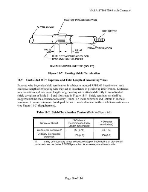
Figure 11-7. Floating Shield Termination<br />
11.9 Unshielded Wire Exposure <strong>and</strong> Total Length of Grounding Wires<br />
Page 60 of 114<br />
<strong>NASA</strong>-STD-8739.4 with Change 6<br />
Exposed wire beyond a shield termination is subject to induced RFI/EMI interference. Any<br />
excessive length of grounding wire may act as an antenna in picking up interference. Distances<br />
to terminations <strong>and</strong> maximum lengths of grounding wires attached directly to an individual<br />
shield are given in Table 11-2 <strong>and</strong> illustrated in Figure 11-8. Shield terminations shall be<br />
staggered behind the connector/accessory 13mm (0.5 inch) minimum <strong>and</strong> 100mm (4 inches)<br />
maximum to assure minimum buildup of the wire bundle diameter in the shield termination area<br />
(see Figure 11-5) (Requirement).<br />
Table 11-2. Shield Termination Control (Refer to Figure 8-8)<br />
Nature of Circuit<br />
Interference sensitive1/<br />
Ordinary interference<br />
protection<br />
X-Distance<br />
Recommended Max<br />
Length mm (Inches)<br />
Y-Distance<br />
mm (Inches)<br />
20 (0.75) 40 (1.5)<br />
100 (4.0) 150 (6.0)<br />
1/ It may be necessary to use conductive adapter backshells that provide full<br />
isolation to secure better RFI/EMI protection for extremely sensitive circuits.