crimping, interconnecting cables, harnesses, and wiring - NASA
crimping, interconnecting cables, harnesses, and wiring - NASA
crimping, interconnecting cables, harnesses, and wiring - NASA

Create successful ePaper yourself
Turn your PDF publications into a flip-book with our unique Google optimized e-Paper software.
Page 89 of 114<br />
<strong>NASA</strong>-STD-8739.4 with Change 6<br />
c. The contact shall be crimped to the conductor per the contact manufacturer’s<br />
recommendations or engineering documentation (Requirement). Indentions shall be symmetrical<br />
<strong>and</strong> centered along the longitudinal axis of the crimp barrel (Requirement). Single crimp indents<br />
shall be located opposite of the barrel weld (see Figure 19-30) (Requirement).<br />
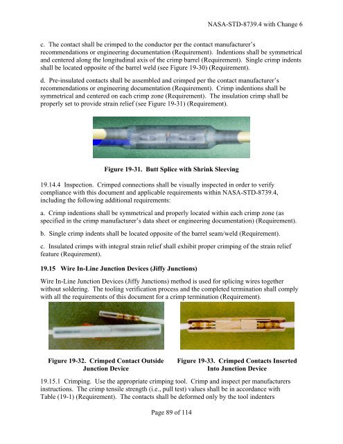
d. Pre-insulated contacts shall be assembled <strong>and</strong> crimped per the contact manufacturer’s<br />
recommendations or engineering documentation (Requirement). Crimp indentions shall be<br />
symmetrical <strong>and</strong> centered on each crimp zone (Requirement). The insulation crimp shall be<br />
properly set to provide strain relief (see Figure 19-31) (Requirement).<br />
Figure 19-31. Butt Splice with Shrink Sleeving<br />
19.14.4 Inspection. Crimped connections shall be visually inspected in order to verify<br />
compliance with this document <strong>and</strong> applicable requirements within <strong>NASA</strong>-STD-8739.4,<br />
including the following additional requirements:<br />
a. Crimp indentions shall be symmetrical <strong>and</strong> properly located within each crimp zone (as<br />
specified in the crimp manufacturer’s data sheet or engineering documentation) (Requirement).<br />
b. Single crimp indents shall be located opposite of the barrel seam/weld (Requirement).<br />
c. Insulated crimps with integral strain relief shall exhibit proper <strong>crimping</strong> of the strain relief<br />
feature (Requirement).<br />
19.15 Wire In-Line Junction Devices (Jiffy Junctions)<br />
Wire In-Line Junction Devices (Jiffy Junctions) method is used for splicing wires together<br />
without soldering. The tooling verification process <strong>and</strong> the completed termination shall comply<br />
with all the requirements of this document for a crimp termination (Requirement).<br />
Figure 19-32. Crimped Contact Outside<br />
Junction Device<br />
Figure 19-33. Crimped Contacts Inserted<br />
Into Junction Device<br />
19.15.1 Crimping. Use the appropriate <strong>crimping</strong> tool. Crimp <strong>and</strong> inspect per manufacturers<br />
instructions. The crimp tensile strength (i.e., pull test) values shall be in accordance with<br />
Table (19-1) (Requirement). The contacts shall be deformed only by the tool indenters