crimping, interconnecting cables, harnesses, and wiring - NASA
crimping, interconnecting cables, harnesses, and wiring - NASA
crimping, interconnecting cables, harnesses, and wiring - NASA

Create successful ePaper yourself
Turn your PDF publications into a flip-book with our unique Google optimized e-Paper software.
Page 88 of 114<br />
<strong>NASA</strong>-STD-8739.4 with Change 6<br />
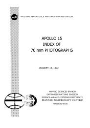
available in both an insulated <strong>and</strong> uninsulated version. The splice provides a very small diameter<br />
profile when installed in a harness.<br />
Figure 19-27. Butt Splice<br />
19.14.1 Preparation. The conductor(s) shall be stripped per (par 10.1) <strong>and</strong> trimmed to length to<br />
allow full insertion into the crimp barrel, such that the conductor ends are visible in the wire<br />
inspection hole (Requirement).<br />
19.14.2 Contact Sizing<br />
a. Single Conductor Configurations. The butt splice contact shall be sized <strong>and</strong> selected<br />
according to the conductor-crimp combinations listed in MIL-DTL-22520G [Table III], or as<br />
specified by the crimp contact manufacturer (Requirement).<br />
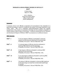
b. Multiple Conductor Configurations. For designs involving the <strong>crimping</strong> of multiple<br />
conductors in one or both ends of the contact (see Figure 19-28), the equivalent wire size (EWS)<br />
must be determined in order to select the appropriate contact size. To calculate EWS, the sum of<br />
the circular mill area (CMA) of the wires to be spliced, multiplied by 1.25, shall determine the<br />
equivalent wire size <strong>and</strong> the corresponding initial contact size (Requirement).<br />
Figure 19-28. Butt Splice Prior to Wire Insertion<br />
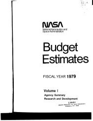
Figure 19-29. Butt Splice Prior to Crimp Figure 19-30. Properly Crimped Butt Splice<br />
19.14.3 Assembly<br />
a. The conductor(s) shall be fully inserted in the crimp barrel, parallel to each other, <strong>and</strong> without<br />
modification to the conductor(s) or crimp barrel (see Figure 19-29) (Requirement).<br />
b. Conductor insulation gap(s) should be approximately equal, but shall comply with the<br />
insulation gap requirements specified in (par 10.1.7.b) for each conductor size (Requirement).