Offshore Cable Installation - Lillgrund - Vattenfall
Offshore Cable Installation - Lillgrund - Vattenfall
Offshore Cable Installation - Lillgrund - Vattenfall

You also want an ePaper? Increase the reach of your titles
YUMPU automatically turns print PDFs into web optimized ePapers that Google loves.
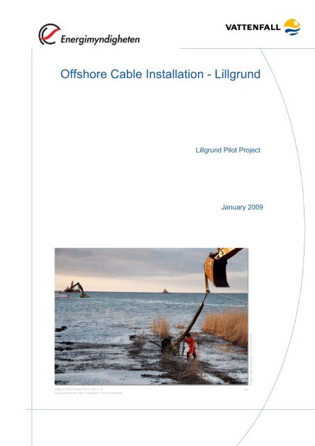
<strong>Offshore</strong> <strong>Cable</strong> <strong>Installation</strong> - <strong>Lillgrund</strong><br />
<strong>Lillgrund</strong> Pilot Project<br />
January 2009
Type of document Document identification Rev. No. Report date Project No.<br />
REPORT 3_2 LG Pilot Report 1.0 January 29, 2009 21858-1<br />
Author Project name<br />
Oscar Unosson <strong>Lillgrund</strong> Pilot Project<br />
Customer Reviewed by<br />
<strong>Vattenfall</strong> Vindkraft AB<br />
Åke Larsson<br />
Approved by<br />
The Reference Group<br />
Distribution No. of pages No. of appendices<br />
The Swedish Energy Agency 30 0<br />
PREFACE<br />
<strong>Vattenfall</strong>’s <strong>Lillgrund</strong> project has been granted financial support from the Swedish Energy<br />
Agency and <strong>Vattenfall</strong> will therefore report and publish experiences and lessons learned<br />
from the project. This report is compiled in a series of open reports describing the<br />
experiences gained from the different aspects of the <strong>Lillgrund</strong> Wind Farm project, for<br />
example construction, installation, operation as well as environmental, public acceptance<br />
and legal issues.<br />
The majority of the report authors have been directly involved in the <strong>Lillgrund</strong> project<br />
implementation. The reports have been reviewed and commented by a reference group<br />
consisting of the <strong>Vattenfall</strong> representatives Sven-Erik Thor (chairman), Ingegerd Bills, Jan<br />
Norling, Göran Loman, Jimmy Hansson and Thomas Davy.<br />
The experiences from the <strong>Lillgrund</strong> project have been presented at two seminars held in<br />
Malmö (4 th of June 2008 and 3 rd of June 2009). In addition to those, <strong>Vattenfall</strong> has<br />
presented various topics from the <strong>Lillgrund</strong> project at different wind energy conferences in<br />
Sweden and throughout Europe.<br />
All reports are available on www.vattenfall.se/lillgrund. In addition to these background<br />
reports, a summary book has been published in Swedish in June 2009. An English version<br />
of the book is foreseen and is due late 2009. The <strong>Lillgrund</strong> book can be obtained by<br />
contacting Sven-Erik Thor at sven-erik.thor@vattenfall.com.<br />
Although the <strong>Lillgrund</strong> reports may tend to focus on problems and challenges, one should<br />
bear in mind that, as a whole, the planning and execution of the <strong>Lillgrund</strong> project has been<br />
a great success. The project was delivered on time and within budget and has, since<br />
December 2007, been providing 60 000 households with their yearly electricity demand.<br />
Sven-Erik Thor,<br />
Project Sponsor, <strong>Vattenfall</strong> Vindkraft AB<br />
September 2009<br />
DISCLAIMER<br />
Information in this report may be used under the conditions that the following reference is<br />
used: "This information was obtained from the <strong>Lillgrund</strong> Wind Farm, owned and operated by<br />
<strong>Vattenfall</strong>."<br />
The views and judgment expressed in this report are those of the author(s) and do not<br />
necessarily reflect those of the Swedish Energy Agency or of <strong>Vattenfall</strong>.<br />
1 (30)
<strong>Offshore</strong> <strong>Cable</strong> <strong>Installation</strong> - <strong>Lillgrund</strong><br />
SUMMARY<br />
This report describes the installation method and the experiences gained during the<br />
installation of the submarine cables for the offshore wind farm at <strong>Lillgrund</strong>. The wind farm<br />
consists of 48 wind turbines and is expected to produce 0.33 TWh annually.<br />
Different aspects of the installation, such as techniques, co-operation between the<br />
installation teams, weather conditions and regulatory and environmental issues are<br />
described in this report. In addition, recommendations and guidelines are provided, which<br />
hopefully can be utilised in future offshore wind projects.<br />
The trenches, in which the submarine cables were laid, were excavated weeks before the<br />
cable laying. This installation technique proved to be successful for the laying of the inter<br />
array cables. The export cable, however, was laid into position with difficulty.<br />
The main reason why the laying of the export cable proved more challenging was due to<br />
practical difficulties connected with the barge entrusted with the cable laying, Nautilus Maxi.<br />
The barge ran aground a number of times and it had difficulties with the thrusters, which<br />
made it impossible to manoeuvre.<br />
When laying the inter array cables, the method specification was closely followed, and the<br />
laying of the cables was executed successfully.<br />
The knowledge and experience gained from the offshore cable installation in <strong>Lillgrund</strong> is<br />
essential when writing technical specifications for new wind plant projects.<br />
It is recommended to avoid offshore cable installation work in winter seasons. That will<br />
lower the chances of dealing with bad weather and, in turn, will reduce the risks.<br />
2 (30)
SAMMANFATTNING<br />
I denna rapport beskrivs genomförande och erfarenheter från sjökabelinstallationen vid<br />
<strong>Lillgrund</strong> vindkraftpark. Vindkraftparken består av 48 vindkraftverk och förväntas årligen<br />
producera cirka 0,33 TWh.<br />
Rapporten behandlar olika aspekter av kabelinstallationen, såsom teknik, samarbete mellan<br />
arbetsgrupper, väderförhållanden samt myndighetskrav. Rapporten innehåller också ett<br />
antal råd och rekommendationer och förhoppningsvis ska dessa kunna tillämpas i framtida<br />
havsvindprojekt.<br />
Sjökablarna förlades i kabeldiken, vilka man grävde åtskilliga veckor innan själva<br />
förläggningen ägde rum. Denna förläggningsteknik fungerade bra för det interna kabelnätet.<br />
Förläggningen av kabeln mellan transformatorplattformen och land, den s.k. exportkabeln,<br />
var dock betydligt mer komplicerad.<br />
Den huvudsakliga anledningen till problemen med förläggningen av exportkabeln var<br />
relaterat till det kabelförläggningsfartyg som användes. Kabelförläggningsfartyget fick sina<br />
propellrar skadade vid en grundstötning och kunde därmed inte manövreras.<br />
Vid förläggningen av det interna kabelnätet följdes metodbeskrivningarna mycket noga och<br />
detta resulterade också i att förläggningen gick mycket bra.<br />
Den kunskap och erfarenhet som erhållits från kabelförläggningsarbetena vid <strong>Lillgrund</strong><br />
utgör ett mycket värdefullt underlag för tekniska specifikationer i kommande<br />
havsvindprojekt.<br />
En klar rekommendation baserad på erfarenheterna från <strong>Lillgrund</strong> är att undvika<br />
kabelinstallationsarbete under vintersäsongen. Detta för att minimera stilleståndstid på<br />
grund av väder samt arbetsmiljörelaterade risker.<br />
3 (30)
TABLE OF CONTENTS<br />
1 INTRODUCTION................................................................................................... 5<br />
2 THE LILLGRUND OFFSHORE WIND FARM ....................................................... 5<br />
2.1 General project information ......................................................................... 5<br />
2.2 <strong>Cable</strong> installation organisation..................................................................... 6<br />
2.3 <strong>Lillgrund</strong> cable system ................................................................................. 6<br />
2.3.1 <strong>Cable</strong> design.................................................................................. 8<br />
3 SUPERVISION ..................................................................................................... 9<br />
3.1 Export cable................................................................................................. 9<br />
3.2 Inter Array cables......................................................................................... 9<br />
4 METHOD DESCRIPTION – OFFSHORE CABLE INSTALLATION...................... 9<br />
4.1 Procedures ................................................................................................ 10<br />
4.1.1 Survey prior trenching.................................................................. 10<br />
4.1.2 Trenching..................................................................................... 11<br />
4.1.3 Soil............................................................................................... 11<br />
4.1.4 <strong>Cable</strong> laying ................................................................................. 11<br />
4.1.5 Weather limitations ...................................................................... 11<br />
4.1.6 Diving restrictions......................................................................... 12<br />
5 EXPORT CABLE ................................................................................................ 12<br />
5.1 <strong>Cable</strong> loading............................................................................................. 12<br />
5.1.1 Arrangement at the factory .......................................................... 12<br />
5.1.2 Loading ........................................................................................ 14<br />
5.1.3 Pre-laying and bad weather conditions........................................ 15<br />
5.2 Pull-in of the cable ..................................................................................... 16<br />
5.3 <strong>Offshore</strong> laying........................................................................................... 19<br />
6 INTER-ARRAY CABLES..................................................................................... 19<br />
6.1 Inspection of C/S Pleijel 6/5-07.................................................................. 19<br />
6.1.1 <strong>Cable</strong> path.................................................................................... 20<br />
6.2 <strong>Installation</strong> of the first three inter-array cables........................................... 23<br />
6.2.1 First cable G02-H02 May 11, 2007 .............................................. 23<br />
6.2.2 <strong>Cable</strong> G02-F02 May 12, 2007...................................................... 25<br />
6.2.3 <strong>Cable</strong> F02-E02 May 13, 2007...................................................... 25<br />
6.3 General comments on the inter-array cable installations........................... 26<br />
6.3.1 J-Tube Caps ................................................................................ 26<br />
6.3.2 Inter-array cable pull-in ................................................................ 26<br />
6.3.3 On the foundations....................................................................... 28<br />
7 COMMENTS AND CONCLUSIONS ................................................................... 29<br />
7.1 Weather dependent operation ................................................................... 29<br />
7.2 Method....................................................................................................... 29<br />
7.3 Environmental impact of the installation operation .................................... 29<br />
8 REFERENCES ................................................................................................... 30<br />
4 (30)
1 INTRODUCTION<br />
The purpose of this report is to describe the installation method and the experience gained<br />
during the installation of the submarine cables for <strong>Lillgrund</strong> offshore wind farm.<br />
The report explains the different aspects of installation, such as the techniques used, the<br />
cooperation between the different subcontractor teams, the impact of weather conditions<br />
and regulatory and environmental issues. It also provides recommendations and<br />
guidelines, which can be applied in future offshore wind plant projects.<br />
2 THE LILLGRUND OFFSHORE WIND FARM<br />
Chapter 2 includes general project information as well as the organisational chart for the<br />
cable installation and an overview of the cable system.<br />
2.1 General project information<br />
<strong>Vattenfall</strong> AB has constructed an offshore wind farm at <strong>Lillgrund</strong>, in the Öresund Sea. The<br />
<strong>Lillgrund</strong> offshore wind farm was under construction between spring 2006 to the end of<br />
2007 when it was completed. The generation from the wind farm is expected to be in the<br />
region of 0.33 TWh annually, which corresponds to the electricity demand of more than 60<br />
000 homes. The wind farm is located off the Swedish coast in an area with shallow water,<br />
see figure 1.<br />
Figure 1. Map over <strong>Lillgrund</strong> in the Öresund Sea<br />
The wind farm consists of 48 wind turbines and one large transformer, for a total of 49<br />
offshore platforms. There were two main suppliers and Siemens Windpower supplied the<br />
5 (30)
wind turbines and electrical system. Phil/Hochtief was the main supplier of the gravity base<br />
structure platforms, which will not be addressed in this report.<br />
2.2 <strong>Cable</strong> installation organisation<br />
The wind turbines were purchased from Siemens Wind Power, and the contract included<br />
high voltage cables in the form of internal grid cables and export cable. The high-voltage<br />
cables were supplied by ABB High Voltage <strong>Cable</strong>s. ABB also used subcontractors for the<br />
installation work, see figure 2.<br />
Constructor:<br />
Main contractors:<br />
Subcontractors:<br />
Seløy<br />
Undervannsservice A/S<br />
Export cable<br />
installation work<br />
Figure 2. Schedule over the contractors<br />
Due to the importance of the submarine cables and the complexity of the installation<br />
<strong>Vattenfall</strong> AB had on-site supervision.<br />
2.3 <strong>Lillgrund</strong> cable system<br />
Siemens Windpower<br />
ABB High Voltage <strong>Cable</strong>s<br />
Svensk<br />
Sjöentreprenad AB<br />
(SSE)<br />
Diving and<br />
transports etc.<br />
The offshore wind farm electrical network includes a series of inter-array cables and an<br />
export cable, see figure 3.<br />
6 (30)<br />
<strong>Vattenfall</strong> AB<br />
Peter Madsen<br />
Rederi A/S<br />
Phil/Hochtief<br />
Baltic <strong>Offshore</strong> AB<br />
Transports etc. Inter array cable<br />
installation work
Figure 3. Inter-array cable layout<br />
Voltage levels are 36 kV for inter-array cables and 145 kV for the export cable. The interarray<br />
cables connect the wind power generators with the transformer platform, W1. The<br />
inter array cables are supplied in three different cross sectional sizes 95 mm 2 , 185 mm 2 and<br />
240 mm 2 . The closer to the transformer platform the larger the dimension of the cable, as<br />
shown in figure 4 below.<br />
95 mm 2<br />
185 mm 2<br />
G G G<br />
≤6 WTG´s<br />
Figure 4. <strong>Cable</strong> Schematic<br />
7 (30)<br />
240 mm 2<br />
7-9 WTG´s 10 WTG´s<br />
36/145 kV<br />
400 mm 2<br />
630 mm 2
There are 48 inter array cables in total. The length of the cables vary, with 15 of the cables<br />
each approximately 350 meters, 28 of the cables approximately 450 meters and 5 cables<br />
up to 1500 meters. The export cable connects the transformer platform with the substation<br />
in Bunkeflo. The export cable is divided into a 7 km submarine cable with a size of 400<br />
mm 2 and a 1,7 km land cable with a size of 630 mm 2 . The submarine cables include an<br />
integrated optic cable. The onshore cable includes a total of 4 separate cables, three<br />
AXLJ 1 x 630 mm 2 as well as an optic cable.<br />
2.3.1 <strong>Cable</strong> design<br />
The different cable types used in <strong>Lillgrund</strong> are described below:<br />
FXCTV 3 x 95 mm 2 36 kV. The cable consists of 3 round, solid copper conductors, each<br />
95 mm 2 . Outside the insulation that surrounds the conductors is a metallic screen of<br />
copper wires. The cable is rated for 36 kV and armoured with 4 mm thick galvanised steel<br />
wires. The entire cable has a diameter of 106 mm and a weight of 16 kg/m.<br />
FXCTV 3 x 185 mm 2 36 kV. Similar design to FXCTV 3 x 95 mm 2 36 kV. The entire cable<br />
has a diameter of 116 mm and a weight of 19 kg/m.<br />
FXCTV 3 x 240 mm 2 36 kV. Similar design to FXCTV 3 x 95 mm 2 36 kV. The entire cable<br />
has a diameter of 120 mm and a weight of 22 kg/m.<br />
FXBTV 3 x 400 mm 2 145 kV, figure 5. Instead of metallic screen of copper wires there is a<br />
metallic sheath of lead alloy. The entire cable has a diameter of 166 mm and a weight of<br />
56 kg/m.<br />
Figure 5. FXBTV 3 x 400 mm 2<br />
AXLJ 1 x 630 mm 2 145 kV. The cable consists of 1 round, compact aluminium conductor<br />
with a cross sectional area of 630 mm 2 . Outside the insulation that surrounds the<br />
conductor there is a metallic screen of copper wires. The cable is not armoured. The entire<br />
cable has a diameter of 74 mm and a weight of 5,9 kg/m.<br />
GASLMLV fibre optic cable. The cable, which is included in the offshore cables, consists<br />
of 48 fibres.<br />
8 (30)
3 SUPERVISION<br />
This report is mainly based on <strong>Vattenfall</strong>’s supervision of the cable installation work<br />
activities. The installation work activities were reported to the <strong>Vattenfall</strong>’s project manager<br />
for the electric systems. The scope of the supervision is detailed below.<br />
3.1 Export cable<br />
Due to the vital importance of the export cable, the loading of the cable onto the barge,<br />
carried out at ABB’s High Voltage <strong>Cable</strong>s harbour was closely supervised by <strong>Vattenfall</strong>. In<br />
addition, the installation of the export cable between Bunkeflo and <strong>Lillgrund</strong> was supervised<br />
both from the barge Nautilus Maxi and from on-shore.<br />
• Supervision onboard the barge, see chapter 3.2 under supervision onboard C/S<br />
Pleijel<br />
• On-shore supervision of the cable pull-in. The focus for the on-shore supervision<br />
was to observe how the cable reacted to the influence of wind, water current, etc<br />
during pull-in. The cable was also influenced by how it was pulled on the rollers and<br />
submerged into the trench.<br />
3.2 Inter Array cables<br />
The supervision of the cable installation consisted of participating as close as possible<br />
onboard C/S Pleijel, M/S Peter Madsen and on the foundations.<br />
• The supervisor onboard C/S Pleijel was positioned at the bow wheel, close to the<br />
cable path, and on the bridge. From the bow, the angle at which the cable went into<br />
the water could be supervised. In addition, it was very important to ensure that the<br />
cable was not too stretched or too loose, and that the cable did not get stuck or<br />
kinked. It was also important to ensure that the cable coils did not get twisted. The<br />
entire operation could be supervised from the bridge on C/S Pleijel and the<br />
communication between the crews was observed closely.<br />
• Supervision onboard M/S Peter Madsen took place on the bridge and in the divers<br />
area. On the bridge, the navigation, with the help of the spuds, was supervised.<br />
From the divers place the real-time, post-lay cable survey was supervised.<br />
• At the foundations, the cable pull-in and the handling of the cable end was being<br />
supervised.<br />
• The supervisor of each vessel reported to <strong>Vattenfall</strong>´s project manager in charge of<br />
the electric installations.<br />
4 METHOD DESCRIPTION – OFFSHORE CABLE INSTALLATION<br />
The offshore part of the export cable installation consisted of trenching, laying, pull-in and<br />
burying. The last 300 meters of the export cable, which was to connect to the transformer<br />
9 (30)
platform, was installed on the seabed temporarily until the transformer platform had been<br />
positioned.<br />
The offshore export cable installation was carried out using the barge Nautilus Maxi. First,<br />
the cable was pulled to shore from the barge. Then, all but the last 300 meters of the cable<br />
was laid into the trench. The remaining was to be connected to the transformer platform.<br />
The inter array cable installation was performed with the help of two ships, C/S Pleijel and<br />
M/S Peter Madsen, and their workboats. C/S Pleijel was responsible for laying down the<br />
inter-array cable between the foundations and M/S Peter Madsen was used as the base for<br />
the divers during the cable pull-in and the post-lay inspection. M/S Peter Madsen also<br />
transported ABB team, tools and material between the foundations.<br />
4.1 Procedures<br />
4.1.1 Survey prior trenching<br />
A survey of the chosen cable route as well as the corridor of around 30 meters each side of<br />
the route was carried out before trenching, see figure 6.<br />
Figure 6. The result of the survey in the form of equidistance curves<br />
The aim of the survey was to investigate if there were any obstacles such as wrecks,<br />
cabling or piping which could potentially interfere with the trenching and laying. A marine<br />
vessel (M/V Sound Seeker) equipped with multi-beam echo sounding system carried out<br />
the survey. Near shore where the depth was below 2 meters (for 1000 meters) a diver<br />
surveyed the cable route and corridor.<br />
10 (30)
A similar survey was carried out after the cable installation and backfilling. The authorities<br />
required a maximal seabed divergence on 0.3 meters between the survey prior trenching<br />
and after backfilling.<br />
4.1.2 Trenching<br />
The trenching was divided into offshore trenching and near shore trenching. In water<br />
depths of more than 1 meter, trenching was defined as offshore trenching. The radiuses of<br />
curves were not allowed to be less than 50 meters. The trench depth had to be 1 meter<br />
below seabed, and the width of the bucket was 1.5 meters. The excavated material was<br />
placed on only one side of the trench to minimise the risk of grounding. During excavation<br />
the bucket was kept as close as possible to the seabed to minimise material spill. There<br />
were restrictions relating to working in inclement weather conditions, due to the risk of<br />
encountering archaeological artefacts, hazardous materials etc.<br />
4.1.3 Soil<br />
Near shore, the surface layer soil consisted of postglacial sand covered by mud. <strong>Offshore</strong>,<br />
the soil consisted of bolder clay, which was very stiff, covered in some areas with a thin<br />
layer of postglacial sand. There were also boulders of up to 2-4 meters in diameter and a<br />
couple of deviations in cable route due to these obstacles.<br />
4.1.4 <strong>Cable</strong> laying<br />
The cable was stretched to ensure a high tension when it was laid down in the trench. It<br />
was important to minimise the tension at turning points so the cable stayed in the trench.<br />
The tension was adjusted by the control system on the barge. A ROV (Remotely Operated<br />
Vehicle), and near shore, a diver confirmed the touch down of the cable in the trench. A<br />
diver carried out the post-lay inspection for the inter-array cables.<br />
Using inflated airbags, the export cable was pulled-in approximately 1000 meters onto the<br />
shore. The inter-array cables were pulled-in to the foundations.<br />
4.1.5 Weather limitations<br />
The pull-in operation to shore required a 48-hour weather window to allow time for<br />
everything from the approval of the pre-lay survey to the post-lay inspection. Pull-in at the<br />
caisson required a weather window of 6 hours. Marine operations cannot be executed<br />
during bad weather. The weather limitations that must be adhered to when performing the<br />
export cable pull-in operation are outlined below:<br />
• Wind (max 7 m/s)<br />
• Waves (max 0.6 m)<br />
• Current (max 0.5 m/s)<br />
• Visibility (min 300 m)<br />
11 (30)
The weather limitations depend on the type of operation carried out, and therefore may vary<br />
for surveying, trenching, cable laying, carrying out ROV-operations and backfilling.<br />
4.1.6 Diving restrictions<br />
Diving operations were planned and executed according to the regulations stated in AFS<br />
1993:57 Dykeriarbeten issued by the Swedish National Work Environmental Authority.<br />
5 EXPORT CABLE<br />
This chapter is divided into two parts, cable loading in Karlskrona and cable laying from<br />
Bunkeflo to <strong>Lillgrund</strong>.<br />
5.1 <strong>Cable</strong> loading<br />
5.1.1 Arrangement at the factory<br />
November 30, 2006:<br />
The submarine export cable was loaded onto the barge Nautilus Maxi from the cable<br />
manufacturer located in Karlskrona. The cable was coiled on the asphalt outside the<br />
factory using a storage space approximately 400 metres from the quay, figure 7.<br />
Figure 7. The cable engine hanging in the crane pulled the coiled export cable from the storage space. As can<br />
be seen above, the cable is transported 400 metres on conveyor idlers.<br />
12 (30)
The loading consisted of many elements. On shore the export cable was equipped with a<br />
cable engine at each end of the cable, one at the storage space and one at the quay,<br />
figure 8. The onshore cable engines were operated one at a time. Behind each cable<br />
engine there was a slack on the cable that is constant at the right velocity. On the barge<br />
there were two additional pulling devices before the cable coiled onto the turntable.<br />
Figure 8. In a tent on the quay a second pulling device was placed. In the tent the cable was marked at exact<br />
lengths.<br />
Because of the necessary slack behind the cable engine the barge had to be moored<br />
approximately 15 meters from the quay, figure 9.<br />
13 (30)
Figure 9. To the right of the picture is the slack from the quay. On the barge are the pulling devices, the capstan<br />
and the vespa on the “gooseneck”.<br />
5.1.2 Loading<br />
There were no problems on shore during the loading. The cable engines were constructed<br />
for the purpose of pulling such large cables and the two men who controlled the cable<br />
engines had a comfortable margin on the slacks.<br />
Initially, the first loading issue was to get the cable around the capstan wheel. When that<br />
succeeded, the ingoing cable wedged the outgoing cable. The cable also seemed to be too<br />
stiff for the capstan. The wheel should therefore optimally have had a bigger diameter to<br />
ensure that the friction would be enough to help the vespa pull the cable onboard. After<br />
getting the cable around the capstan, the next issue was the vespa. The vespa turned out<br />
to be too small for the cable diameter. When the vespa was adjusted to allow the cable<br />
through, it didn’t receive enough power to provide the required tension to the cable.<br />
Though the first layer on the turntable went well, the lack of tension on the following layers<br />
showed that adjustments needed to be made.<br />
December 1, 2006:<br />
After attempts using harder bindings around the vespa as well as a higher hydraulic<br />
pressure, an electric motor was installed with a wheel which pressed onto the cable at the<br />
capstan, figure 10.<br />
14 (30)
December 2, 2006:<br />
Figure 10. The motor installed with the wheel pressing onto the cable at the capstan.<br />
With the help of the electric motor and wheel, the whole length of the cable was loaded<br />
onboard. An average speed of loading of 5-6 meters per minute was planned, but at times<br />
the speed was exceeding 10 meters per minute. When the loading was finished, a fibre<br />
test confirmed that the tension in the cable was accurate.<br />
5.1.3 Pre-laying and bad weather conditions<br />
The issues identified during loading raised questions about the ability to lay and reload the<br />
cable in the case of bad weather conditions. Carrying out a pre-laying exercise in a<br />
neighbouring archipelago solved this.<br />
Before the pre-laying exercise was carried out, a new construction was added to the<br />
“gooseneck” which included an extra vespa. The new construction was an extension of the<br />
“gooseneck” where the vespa was built-in, figure 11.<br />
15 (30)
December 3, 2006:<br />
Figure 11. An extension was built on the “gooseneck” where the vespa was built-in.<br />
A practice run with about 50 meters of cable was pre-laid, on a similar depth as <strong>Lillgrund</strong><br />
(10 meters). The practice run in the archipelago worked out very well. Due to the<br />
difficulties loading the cable the barge had been delayed for about two days but was now<br />
finally ready for the transit to Klagshamn.<br />
December 3-15, 2006:<br />
During this particular period there were poor weather conditions on the south coast of<br />
Sweden. The barge had to wait in Karlskrona an additional few days for better weather.<br />
When the barge finally sailed to Klagshamn, the weather conditions were too bad for cable<br />
laying and the barge had to wait in the harbour of Limhamn.<br />
5.2 Pull-in of the cable<br />
December 16, 2006:<br />
After two weeks of waiting for better weather, it was finally time to make the pull-in of the<br />
export cable. The weather forecast predicted acceptable weather conditions for the next<br />
couple of days, so the barge went out to the starting position.<br />
December 17, 2006:<br />
The weather made a turn for the worse and made it impossible to guarantee a safe pull-in.<br />
December 18, 2006:<br />
The weather conditions improved and an attempted pull-in of the cable was approved.<br />
Although the barge had moved slightly from its position due to the wind, this did not pose a<br />
16 (30)
problem for the pull-in. The pull-in took place with the use of inflated airbags, which took<br />
the cable towards shoreline, figure 12.<br />
Figure 12. Inflated airbags took the cable towards shoreline.<br />
In front of the cable, a small workboat was used to keep the course towards the excavators.<br />
The tide was higher than expected, so the excavators could not reach as far as planned.<br />
Instead, a larger workboat was used to reach the steel wire with the cable. The wind came<br />
from the back but the water currents came from the starboard side. The steel wire was too<br />
heavy for the workboat. A bigger workboat managed to reach the steel wire with the end of<br />
the cable. When the Chinese finger was secured to the steel wire, the excavator and an<br />
onshore winch fulfilled the pull-in, figure 13.<br />
Figure 13. The cable pull-in made by the excavators and a pull-in winch. A bigger workboat and two divers<br />
were also used.<br />
Near shore, the cable was pulled on rollers because of the heaviness of the cable, figure<br />
14.<br />
17 (30)
Figure 14. The cable pull-in at the shoreline made by the excavator and a pull-in winch.<br />
When the pull-in was ready the cable was submerged into the pre-excavated trench.<br />
December 19, 2006:<br />
The floating bags that were used during the submerging of the cable were not disposed of<br />
immediately, which caused temporary debree scattered along the shoreline. Divers walked<br />
or swam the whole shoreline in the bay to collect floating bags, figure 15.<br />
Figure 15. The shoreline was filled of floating bags after the submerging.<br />
18 (30)
5.3 <strong>Offshore</strong> laying<br />
December 18-19, 2006:<br />
There was a manoeuvrability issue when the barge was supposed to position itself above<br />
the pre-excavated trench. It is possible that one of the barge thrusters had been damaged<br />
during the pull-in, while positioned on the sandbar. It was still able to manoeuvre itself into<br />
position as the other thrusters were still operational.<br />
The first few kilometers of cable laying went as planned, and the cable was positioned in<br />
the trench. However, the second barge thruster hit something, possibly another sandbar or<br />
the excavated material. This second loss of a thruster made the barge unmanoeuvrable.<br />
The barge was escorted to the transformer platform with the help of the T/B Nautilus<br />
Mammut, leaving the cable within 10 meters of the trench. The last approximately 300<br />
meters were laid to the north of the trench, instead of the south, as planned, because it<br />
required less of a turn from the barge.<br />
February 10, 2007:<br />
Approximately 5 kilometers of the cable, which was lying within 10 meters of the trench,<br />
was reloaded onto the barge, and relaid to its correct position in the trench. During the time<br />
of inactivity from December 2006 to February 2007, the trench had partly filled in with mud.<br />
Hence, SSE divers had to flush the cable to its right depth in the trench.<br />
July 1, 2007:<br />
Svensk Sjöentreprenad finally laid the remaining 300 meters of cable in the trench at the<br />
end of July/ beginning of August 2007 after the transformer platform had been installed.<br />
6 INTER-ARRAY CABLES<br />
6.1 Inspection of C/S Pleijel 6/5-07<br />
At the arrival of the C/S Pleijel, the draught in bow and stern were measured to read 3.0<br />
and 3.4 meters. The inspection on board included:<br />
• <strong>Cable</strong> path<br />
• Engine room<br />
• Operating system<br />
• Navigation system<br />
Everything on board looked suitable upon visual inspection of the engine room. The<br />
engineer carried out routine tests on a continuous basis.<br />
The operating system consisted of the main engine in the stern, two thrusters on the<br />
starboard side and two thrusters on the port side (bow and stern thrusters). The compass<br />
thrusters were not utilised due to the shallowness of the water in <strong>Lillgrund</strong>.<br />
19 (30)
Due to the importance of exact navigation C/S Pleijel was equipped with DGPS and<br />
dynamic positioning system (DP). The accuracy of the DP is nearly 1-2 cm in normal<br />
conditions. Before every cable laying operation, the crew positions a profiler in the bow.<br />
The profiler films the trench that is displayed on the bridge. The monitor verifies the real<br />
position of the trench from which the DP can be coordinated.<br />
6.1.1 <strong>Cable</strong> path<br />
C/S Pleijel was loaded with the inter-array cables in the form of two coils at ground deck.<br />
The stern of the ground deck was equipped with a turntable. The turntable was necessary<br />
because the bridge above covered half of the coil, figure 16. The deck above the coils<br />
(shelter deck) had a hatch cover that remained open during installation.<br />
Figure 16. The stern coil was equipped with a turntable.<br />
From the cable coils the cables were pulled up through the gooseneck with a wire, see<br />
figure 17. The gooseneck is located on the shelter deck and is articulated to avoid kinks on<br />
the cable. Depending from which coil the cable was pulled the angle of the gooseneck is<br />
adjusted. It was important to ensure that the cable did not get any kinks when being pulled<br />
up.<br />
20 (30)
Figure 17. The gooseneck above the coils on the shelter deck.<br />
After the gooseneck came, the linear cable engine would transport the cable into the water<br />
by the bow wheel or, under poor conditions, back to the coils, figure 18.<br />
21 (30)
Figure 18. The linear cable engine transports the cable forward to the bow wheel.<br />
The bow wheel operator controlled the speed of the cable engine, figure 19. The bow<br />
wheel operator was positioned in the bow where he had a good overview of the cable<br />
laying.<br />
Figure 19. The bow wheel operator leads the operation at the bow wheel.<br />
22 (30)
6.2 <strong>Installation</strong> of the first three inter-array cables<br />
This chapter describes the procedure and the difficulties experienced during the installation<br />
of the first three inter-array cables. Most of the mistakes were corrected after these three<br />
installations.<br />
6.2.1 First cable G02-H02 May 11, 2007<br />
The first cable was laid between the G02 and the H02 foundations. C/S Pleijel had<br />
problems with the navigation system the morning of the installation, possibly due to the<br />
following explanations:<br />
• The conditions are often worse at dawn or sunset when there are a lot of reflections<br />
• The weather was cloudy and rainy<br />
• There was a NATO exercise in Östersjön<br />
Another difficulty was that the linear cable engine did not manage to hold the cable in place.<br />
Steel plates were installed so the cable could not move laterally.<br />
To be sure it worked, the profiler, which was installed in the bow, ran a sound of the bottom.<br />
The lead line and the results from the profiler should correlate. Figure 20 shows the profiler<br />
assembled on a steel tube.<br />
Figure 20. The profiler seen is attached to a steel tube, and is fastened at the bow, one meter below sea level.<br />
23 (30)
Figure 21, below, presents the plot of the seabed as shown by the profiler.<br />
Figure 21. Plot of the profile above the trench. The blue is the surface of the seabed and the red circles every<br />
second meter from the profiler in the centre. The profiler is not directly over the trench.<br />
During the post-lay survey, M/S Peter Madsen followed a distance too short behind the<br />
diver with the umbilical hanging off of the stern end of the boat. The umbilical should have<br />
been hanging off the front, far from the engine, to reduce the risk of damage.<br />
M/S Peter Madsen was without a driver for the while that the crew were going for the loose<br />
cable end in their workboat. The cook steward was the only one left on M/S Peter Madsen,<br />
and it would have been better if the captain or the star man would have stayed on the ship<br />
at all times.<br />
During the time the cables were positioned on the floaters, operators had to be aware that<br />
the ocean currents could have moved in a direction, which could have caused a kink in the<br />
cable during the pull-in, figure 22.<br />
24 (30)
Figure 22. The water current affected position of the cable and the floaters during the pull-in.<br />
6.2.2 <strong>Cable</strong> G02-F02 May 12, 2007<br />
During the second cable laying between G02 and F02 the weather conditions were good.<br />
C/S Pleijel did not have any significant difficulties; the team just needed to do the work a<br />
couple of times to get into a routine.<br />
This time, during the post-lay survey of the cable, M/S Peter Madsen followed the diver at a<br />
larger distance and with the umbilical hanging off the front of the boat.<br />
The communication between C/S Pleijel and M/S Peter Madsen could have been better. It<br />
was frustrating for all involved when one party did not know what the other was doing.<br />
6.2.3 <strong>Cable</strong> F02-E02 May 13, 2007<br />
Communication problems were apparent when M/S Peter Madsen went to the wrong<br />
foundation to install this segment of cable. This was corrected, and work to improve the<br />
communication between the teams has continued since.<br />
25 (30)
6.3 General comments on the inter-array cable installations<br />
6.3.1 J-Tube Caps<br />
In every foundation there was a j-tube from the seabed to the top of the foundation, which<br />
was designed for the cable. One meter below the seabed, a bell-mouth with an enclosure<br />
cap, was mounted on the j-tube. The enclosure cap had to be removed before the cable<br />
pull-in, figure 23. Mud had filled in outside of the enclosure cap, requiring divers to vacuum<br />
the space before every pull-in so the cap could be removed. Because of the water current<br />
direction, clearing the space in front of the caps took 15 - 30 minutes each on the south<br />
sides of the foundations and up to two hours on the north sides of the foundations.<br />
6.3.2 Inter-array cable pull-in<br />
Figure 23. The enclosure cap removed from the bell mouth.<br />
At each foundation location, C/S Pleijel began the operation by pulling the cable through the<br />
j-tube of the foundation, first, feeding the cable from the bell-mouth underwater up through<br />
the shaft and out of the foundation top. The other end of the cable was floated towards the<br />
second foundation, until it got within 30 - 40 meters from it, before the cable was pulled<br />
through that second foundation, figure 24.<br />
26 (30)
Figure 24. <strong>Cable</strong> floating from C/S Pleijel, M/S Peter Madsen in the background.<br />
Due to water current pulling the cable there was sometimes a risk that the cable would get<br />
a kink. During those risky pull-in operations the workboat pulled the cable to minimise this<br />
risk, figure 25.<br />
Figure 25. A workboat pulled the cable to minimise the risk for a kink<br />
27 (30)
6.3.3 On the foundations<br />
To ensure that enough cable was provided to each foundation, the cable was pulled 6 -<br />
8 meters above the j-tube top. The cable armour was removed for this length before the<br />
cable was secured, see figure 26 below.<br />
Figure 26. The cable armour was removed with help of an angle grinder<br />
At every foundation where the cable laying was ending there was more cable than<br />
necessary. This extra length of cable was cut off using a tiger saw, figure 27.<br />
Figure 27. A tiger saw was used to cut the excess length of cable<br />
28 (30)
7 COMMENTS AND CONCLUSIONS<br />
The cable installation process was complex and an important step for <strong>Vattenfall</strong> AB,<br />
considering the limited experiences previous to <strong>Lillgrund</strong> of building offshore wind farms.<br />
7.1 Weather dependent operation<br />
The cable installation is very dependant on weather conditions. The longer time the<br />
installation is predicted to take, the more important is it to choose the right season. In<br />
<strong>Lillgrund</strong>, for example, the export cable was scheduled to be installed in October but first<br />
attempts were postponed until December due to poor weather conditions.<br />
In conclusion, it is recommended to schedule the cable installation work during statistically<br />
good weather seasons, attempting to avoid winter by a comfortable margin.<br />
7.2 Method<br />
The method of excavating the trenches first and then coming back to lay the cable weeks<br />
later worked well for the installation of the inter-array cables. However, the export cable<br />
was only installed correctly after many setbacks.<br />
Sweden and Denmark do not share the same diving regulations. Sweden allows diving<br />
from a moving ship and Denmark requires the ship to have its spuds down and the engines<br />
turned off. This was confusing for the Danish crew in the beginning of the installations.<br />
In <strong>Lillgrund</strong>, the seabed soil profile consisted of mainly very stiff bolder clay. The clay was<br />
advantageous for excavation because of its stiffness and allowed the trench to have almost<br />
vertical walls. It also allowed the excavated material to remain close to the trench during<br />
the backfilling. In the few areas where the seabed was not as stiff, a pre-lay excavation<br />
was necessary.<br />
Another advantage of the stiff bolder clay was that very few particles of the material<br />
followed the water currents during the excavation. In areas with soft seabed material, and<br />
at areas with a depth less than 3 - 5 meters, seabed material was clouding the water by the<br />
thrusters on the cable ship.<br />
7.3 Environmental impact of the installation operation<br />
The environment is affected by the installation both during the excavation and during the<br />
cable laying. During the excavation, small particles from the clay followed the water<br />
currents and, depending on how strong the current was, the particle cloud could be<br />
hundreds of meters in length. A supervisor for the authorities notified the operators that this<br />
was a problem early in the excavation, and was quickly addressed by limiting the height of<br />
the bucket over the seabed.<br />
29 (30)
During the cable laying, when the trench was completed, the impact on the environment<br />
was considerably lower. The clay particles normally settled very quickly, often within less<br />
than an hour.<br />
A minimum of one meter of installation depth was required, but was not met in some<br />
locations. Close to the shore, some rocks were found in the trench while the cable was<br />
being water jetted. The installation at a depth of half a meter was approved in these cases<br />
because blasting would be a much worse alternative from an environmental point of view.<br />
At trench sections where the depth was less than half a meter, the trench had to be covered<br />
by rocks.<br />
8 REFERENCES<br />
[1] Ljung, P. Method description Array cable installation for <strong>Lillgrund</strong>. February 21, 2007<br />
[2] Madsen, M. Conversation during the first inter-array cable laying. May 11, 2007<br />
30 (30)