THE XYZs OF USING A SCOPE Tektronix
THE XYZs OF USING A SCOPE Tektronix
THE XYZs OF USING A SCOPE Tektronix

You also want an ePaper? Increase the reach of your titles
YUMPU automatically turns print PDFs into web optimized ePapers that Google loves.
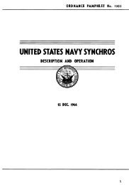
Figure 27.<br />
X-Y COMPONENT CHECKING requires the transistor checker shown above. With it<br />
connected to your scope and the scope in the X-Y mode, patterns like those<br />
illustrated indicate the component’s condition. The waveforms shown are found<br />
when the components are not in a circuit; in-circuit component patterns will differ<br />
because of resistors and capacitors associated with the component.<br />
pressure and volume of liquids Differential Measurements<br />
and gasses are more examples. The ADD vertical mode and the<br />
With the proper transducer, you channel 2 INVERT button of your<br />
can use your scope to make any 2200 Series scope let you make<br />
of these measurements.<br />
differential measurements.<br />
Often differential measurements<br />
let you eliminate undesirable<br />
components from a signal that<br />
you’re trying to measure. If you<br />
have a signal that’s very similar<br />
to the unnecessary noise, the<br />
set up is simple. Put the signal<br />
with the spurious information on<br />
channel 1. Connect the signal<br />
that is like unwanted components<br />
to channel 2. Set both<br />
input coupling switches to DC<br />
(use AC if the DC components of<br />
the signal are too large), and<br />
select the alternate vertical<br />
mode by moving the VERTICAL<br />
MODE switches to BOTH and<br />
ALT<br />
Now set your volts/division<br />
switches so that the two signals<br />
are about equal in amplitude.<br />
Then you can move the righthand<br />
VERTICAL MODE switch<br />
to ADD and press the INVERT<br />
button so that the common<br />
mode signals have opposite<br />
polarities.<br />
PART II<br />
If you use the channel 2<br />
VOLTS/DIV switch and VAR control<br />
for maximum cancellation of<br />
the common signal, the signal<br />
that remains on-screen will only<br />
contain the desired part of the<br />
channel 1 input signal. The two<br />
common mode signals have<br />
cancelled out leaving only the<br />
difference between the two.<br />
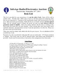
Figure 28.<br />
DIFFERENTIAL MEASUREMENTS allow you to remove unwanted information from a<br />
signal anytime you have another signal that closely resembles the unwanted components.<br />
For example, the first photo shows a 1 kHz square contaminated by a 60 Hz<br />
sine wave. Once the common-mode component (the sine wave) is input to channel 2<br />
and that channel is inverted, the signals can be added with the ADD vertical mode.<br />
The result is shown in the second photo.<br />
Using the Z Axis<br />
Remember from Part I that the<br />
CRT in your scope has three<br />
axes of information: X is the horizontal<br />
component of the graph,<br />
Y is the vertical, and Z is the<br />
brightness or darkness of the<br />
electron beam. The 2200 Series<br />
scopes all have an external<br />
Z-axis input BNC connector on<br />
the back of the instrument. This<br />
input lets you change the<br />
brightness (modulate the intensity)<br />
of the signal on the screen<br />
with an external signal. The<br />
Z-axis input will accept a signal<br />
of up to 30 V through a usable<br />
frequency range of DC to 5 MHz.<br />
Positive voltages decrease the<br />
brightness and negative voltages<br />
increase it; 5 volts will<br />
cause a noticeable change.<br />
The Z-axis input is an advantage<br />
to users that have their instruments<br />
set up for a long<br />
series of tests. One example is<br />
the testing of high fidelity<br />
equipment illustrated by<br />
Figure 29.<br />
27