THE XYZs OF USING A SCOPE Tektronix
THE XYZs OF USING A SCOPE Tektronix
THE XYZs OF USING A SCOPE Tektronix

Create successful ePaper yourself
Turn your PDF publications into a flip-book with our unique Google optimized e-Paper software.
MEASUREMENT TECHNIQUES CONT.<br />
c <strong>SCOPE</strong><br />
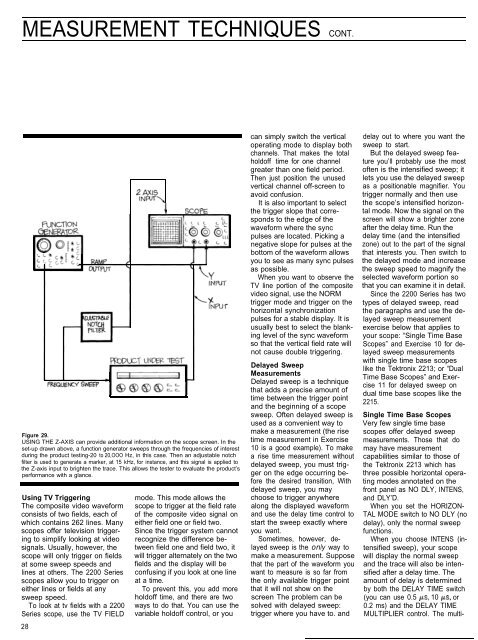
Figure 29.<br />
<strong>USING</strong> <strong>THE</strong> Z-AXIS can provide additional information on the scope screen. In the<br />
set-up drawn above, a function generator sweeps through the frequencies of interest<br />
during the product testing-20 to 20,OOO Hz, in this case. Then an adjustable notch<br />
filter is used to generate a marker, at 15 kHz, for instance, and this signal is applied to<br />
the Z-axis input to brighten the trace. This allows the tester to evaluate the product’s<br />
performance with a glance.<br />
Using TV Triggering<br />
The composite video waveform<br />
consists of two fields, each of<br />
which contains 262 lines. Many<br />
scopes offer television triggering<br />
to simplify looking at video<br />
signals. Usually, however, the<br />
scope will only trigger on fields<br />
at some sweep speeds and<br />
lines at others. The 2200 Series<br />
scopes allow you to trigger on<br />
either lines or fields at any<br />
sweep speed.<br />
To look at tv fields with a 2200<br />
Series scope, use the TV FIELD<br />
28<br />
mode. This mode allows the<br />
scope to trigger at the field rate<br />
of the composite video signal on<br />
either field one or field two.<br />
Since the trigger system cannot<br />
recognize the difference between<br />
field one and field two, it<br />
will trigger alternately on the two<br />
fields and the display will be<br />
confusing if you look at one line<br />
at a time.<br />
To prevent this, you add more<br />
holdoff time, and there are two<br />
ways to do that. You can use the<br />
variable holdoff control, or you<br />
can simply switch the vertical<br />
operating mode to display both<br />
channels. That makes the total<br />
holdoff time for one channel<br />
greater than one field period.<br />
Then just position the unused<br />
vertical channel off-screen to<br />
avoid confusion.<br />
It is also important to select<br />
the trigger slope that corresponds<br />
to the edge of the<br />
waveform where the sync<br />
pulses are located. Picking a<br />
negative slope for pulses at the<br />
bottom of the waveform allows<br />
you to see as many sync pulses<br />
as possible.<br />
When you want to observe the<br />
TV line portion of the composite<br />
video signal, use the NORM<br />
trigger mode and trigger on the<br />
horizontal synchronization<br />
pulses for a stable display. It is<br />
usually best to select the blanking<br />
level of the sync waveform<br />
so that the vertical field rate will<br />
not cause double triggering.<br />
Delayed Sweep<br />
Measurements<br />
Delayed sweep is a technique<br />
that adds a precise amount of<br />
time between the trigger point<br />
and the beginning of a scope<br />
sweep. Often delayed sweep is<br />
used as a convenient way to<br />
make a measurement (the rise<br />
time measurement in Exercise<br />
10 is a good example). To make<br />
a rise time measurement without<br />
delayed sweep, you must trigger<br />
on the edge occurring before<br />
the desired transition, With<br />
delayed sweep, you may<br />
choose to trigger anywhere<br />
along the displayed waveform<br />
and use the delay time control to<br />
start the sweep exactly where<br />
you want.<br />
Sometimes, however, delayed<br />
sweep is the only way to<br />
make a measurement. Suppose<br />
that the part of the waveform you<br />
want to measure is so far from<br />
the only available trigger point<br />
that it will not show on the<br />
screen The problem can be<br />
solved with delayed sweep:<br />
trigger where you have to. and<br />
delay out to where you want the<br />
sweep to start.<br />
But the delayed sweep feature<br />
you’ll probably use the most<br />
often is the intensified sweep; it<br />
lets you use the delayed sweep<br />
as a positionable magnifier. You<br />
trigger normally and then use<br />
the scope’s intensified horizontal<br />
mode. Now the signal on the<br />
screen will show a brighter zone<br />
after the delay time. Run the<br />
delay time (and the intensified<br />
zone) out to the part of the signal<br />
that interests you. Then switch to<br />
the delayed mode and increase<br />
the sweep speed to magnify the<br />
selected waveform portion so<br />
that you can examine it in detail.<br />
Since the 2200 Series has two<br />
types of delayed sweep, read<br />
the paragraphs and use the delayed<br />
sweep measurement<br />
exercise below that applies to<br />
your scope: “Single Time Base<br />
Scopes” and Exercise 10 for delayed<br />
sweep measurements<br />
with single time base scopes<br />
like the <strong>Tektronix</strong> 2213; or “Dual<br />
Time Base Scopes” and Exercise<br />
11 for delayed sweep on<br />
dual time base scopes like the<br />
2215.<br />
Single Time Base Scopes<br />
Very few single time base<br />
scopes offer delayed sweep<br />
measurements. Those that do<br />
may have measurement<br />
capabilities similar to those of<br />
the <strong>Tektronix</strong> 2213 which has<br />
three possible horizontal operating<br />
modes annotated on the<br />
front panel as NO DLY, INTENS,<br />
and DLY’D.<br />
When you set the HORIZON-<br />
TAL MODE switch to NO DLY (no<br />
delay), only the normal sweep<br />
functions.<br />
When you choose INTENS (intensified<br />
sweep), your scope<br />
will display the normal sweep<br />
and the trace will also be intensified<br />
after a delay time. The<br />
amount of delay is determined<br />
by both the DELAY TIME switch<br />
(you can use 0.5 ps, 10 ps, or<br />
0.2 ms) and the DELAY TIME<br />
MULTIPLIER control. The multi-