

ZBT Memory: One 2MB memory bank was used for this project
ZBT Memory: One 2MB memory bank was used for this project
ZBT Memory: One 2MB memory bank was used for this project

Create successful ePaper yourself
Turn your PDF publications into a flip-book with our unique Google optimized e-Paper software.
1. Overview<br />
Goals<br />
The purpose of the <strong>project</strong> <strong>was</strong> to implement a character recognition system using Xilinx’s<br />
Virtex-II Multimedia Board and Xilinx’s development software plat<strong>for</strong>ms, ISE and EDK. The<br />
<strong>project</strong> is an offshoot of our ECE496 Design Project where we had to develop a robotic rover<br />
capable of gathering and processing visual and audio clues in predefined <strong>for</strong>mats. The character<br />
recognition system would augment the robot’s existing image processing and autonomous<br />
capabilities by enabling it to recognize and interpret characters within the images of clues it<br />
captures with its webcam.<br />
Description of IPs<br />
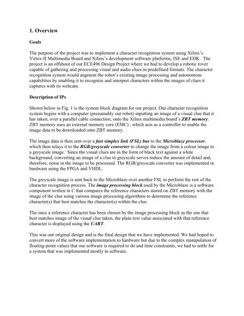
Shown below in Fig. 1 is the system block diagram <strong>for</strong> our <strong>project</strong>. Our character recognition<br />
system begins with a computer (presumably our robot) inputting an image of a visual clue that it<br />
has taken, over a parallel cable connection, onto the Xilinx multimedia board’s <strong>ZBT</strong> <strong>memory</strong>.<br />
<strong>ZBT</strong> <strong>memory</strong> uses an external <strong>memory</strong> core (EMC) , which acts as a controller to enable the<br />
image data to be downloaded onto <strong>ZBT</strong> <strong>memory</strong>.<br />
The image data is then sent over a fast simplex link (FSL) bus to the Microblaze processor,<br />
which then relays it to the RGB/greyscale converter to change the image from a colour image to<br />
a greyscale image. Since the visual clues are in the <strong>for</strong>m of black text against a white<br />
background, converting an image of a clue to greyscale serves reduce the amount of detail and,<br />
there<strong>for</strong>e, noise in the image to be processed. The RGB/greyscale converter <strong>was</strong> implemented in<br />
hardware using the FPGA and VHDL.<br />
The greyscale image is sent back to the Microblaze over another FSL to per<strong>for</strong>m the rest of the<br />
character recognition process. The image processing block <strong>used</strong> by the Microblaze is a software<br />
component written in C that compares the reference characters stored on <strong>ZBT</strong> <strong>memory</strong> with the<br />
image of the clue using various image processing algorithms to determine the reference<br />
character(s) that best matches the character(s) within the clue.<br />
The once a reference character has been chosen by the image processing block as the one that<br />
best matches image of the visual clue taken, the plain text value associated with that reference<br />
character is displayed using the UART.<br />
This <strong>was</strong> our original design and is the final design that we have implemented. We had hoped to<br />
convert more of the software implementation to hardware but due to the complex manipulation of<br />
floating-point values that our software is required to do and time constraints, we had to settle <strong>for</strong><br />
a system that <strong>was</strong> implemented mostly in software.
Fig. 1: System block diagram of character recognition system.<br />
2. Outcome<br />
The each individual block works on its own. However, we haven’t had the time to put everything<br />
together because the conversion of the image processing block from MATLAB to C <strong>was</strong><br />
completed only recently and <strong>was</strong> too big to fit onto the BRAMs of the multimedia board.<br />
The character recognition software <strong>was</strong> first implemented in MATLAB, then the code <strong>was</strong><br />
transferred to C on ugsparc machines (with gcc), and finally it <strong>was</strong> transferred to the Xilinx board<br />
using XPS. Currently it is running successfully on all three plat<strong>for</strong>ms. The program is fairly<br />
robust as it <strong>was</strong> able to make reasonable judgments regarding the degree of similarity between<br />
two images even in the presence of noise artificially added to images.<br />
If more time <strong>was</strong> available to us, we would put all the IPs together and test the overall result.<br />
As described in the overview the image is supposed to be converted to greyscale and then passed<br />
on to the character recognition block. Right now, both character recognition and greyscale<br />
converter work on their own but do not communicate with each other.
3. Description of the Blocks<br />
<strong>ZBT</strong> <strong>Memory</strong>: <strong>One</strong> <strong>2MB</strong> <strong>memory</strong> <strong>bank</strong> <strong>was</strong> <strong>used</strong> <strong>for</strong> <strong>this</strong> <strong>project</strong>. The <strong>memory</strong> occupies<br />
addresses 0x80600000 to 0x807fffff. The design provided by Tutorial M08 worked, so no<br />
changes were necessary. For <strong>this</strong> <strong>project</strong>, the <strong>memory</strong> has been set up to operate at 50MHz in<br />
order to match the clock speed of the FSLs <strong>used</strong> in the RGB/greyscale converter. The system <strong>was</strong><br />
tested using C application to write and read data to and from the <strong>ZBT</strong> <strong>memory</strong>.<br />
clk_align_v1_00_a: The clk_align core <strong>was</strong> <strong>used</strong> ensure that the clock to the <strong>ZBT</strong> <strong>memory</strong> is<br />
properly aligned to the internal clk. The design provided by Tutorial M08 worked, so no changes<br />
were necessary.<br />
fsl_v20_v1_00_b: Three instances of fast simplex link (FSL) were <strong>used</strong> in <strong>this</strong> <strong>project</strong>. The FSL<br />
instance, download_link, <strong>was</strong> <strong>used</strong> to download images quickly from the hard drive onto <strong>ZBT</strong><br />
<strong>memory</strong>. The other 2 instances, mb_to_hw and hw_to_mb , were <strong>used</strong> relay image in<strong>for</strong>mation<br />
from <strong>ZBT</strong> <strong>memory</strong> to the RGB/greyscale converter hardware (using the Microblaze as an<br />
intermediary) and to send the output of the RGB/greyscale converter to the Microblaze <strong>for</strong> further<br />
processing, respectively. The standard interfaces that came with fsl_v20_v1_00_b worked, so no<br />
changes were necessary. download_link <strong>was</strong> tested by downloading images to <strong>memory</strong> and then<br />
timing the difference between <strong>ZBT</strong> with FSL and ZAB without FSL. It turned out that <strong>ZBT</strong> with<br />
FSL <strong>was</strong> about 6 times faster than without.<br />
RGB/Greyscale Converter (idct.vhd): This converter is <strong>used</strong> convert a colour image into a<br />
greyscale image to reduce the amount of in<strong>for</strong>mation in the image that the Image Processing<br />
software block is required to process. The design <strong>was</strong> adapted from Xilinx’s Application Notes<br />
XAPP529 and XAPP637. Both are available on the Xilinx’s website, under Application Notes.<br />
The FSL wrapper code <strong>for</strong> XAPP529’s <strong>was</strong> <strong>used</strong> to integrate the RGB/greyscale converter into<br />
the <strong>project</strong> using FSLs (specifically using FSL instances mb_to_hw and hw_to_mb). The convert<br />
takes in 24-bit pixel data and masks the red and blue components of the pixel, leaving only the<br />
green component. The resulting image is a greyscale. A test bench <strong>for</strong> <strong>this</strong> block <strong>was</strong> created<br />
using ISE’s Test Bench Wave<strong>for</strong>m tool. The output of the simulation is shown below.<br />
Fig. 2: Simulation of RGB/greyscale converter.
Character Recognition Software:<br />
As discussed earlier, the character recognition software <strong>was</strong> intended to be <strong>used</strong> on an<br />
autonomous rover which gathers visual clues (consists of black text printed on white<br />
background). The ability to recognize characters in a clue is critical <strong>for</strong> giving maximum<br />
autonomy to the rover.<br />
The algorithm <strong>for</strong> character recognition <strong>was</strong> not developed by us. In fact, some research <strong>was</strong> done<br />
on the web to find out a good way of solving <strong>this</strong> problem. Many different algorithm exist but the<br />
one we <strong>used</strong> is described in the paper “Text Character Recognition: Identification of Hebrew<br />
Letters” by Lavi Zmstein of University of Florida.<br />
(http://www.mil.ufl.edu/publications/fcrar03/%7BHebrew%7D%20Letter%20Recognition.pdf)<br />
In <strong>this</strong> histogram method of character recognition we first find the location of all black pixels in<br />
the image. Once that is done, the centroid of each character is calculated. Then the distance<br />
vectors are calculated <strong>for</strong> each pixel from the centroid. These distances are then normalized by<br />
the maximum distance from the centroid to get some values between 0 and 1. Then 21 bins are<br />
created between 0 and 1 with 0.05 increments. All normalized distance values are then put into<br />
these bins according to their magnitude. These bins are normalized again by the total number of<br />
bins. Finally <strong>this</strong> procedure is repeated <strong>for</strong> the input image which has to be classified. Once these<br />
profiles are created <strong>for</strong> the training images and the input image, each training profile is compared<br />
to input image profile to produce a number which represent the likelihood that two images are<br />
same. If the number is closer to zero, it represent a higher likelihood.<br />
Now each block of <strong>this</strong> algorithm will be described <strong>for</strong> both Matlab and C code respectively.<br />
classify_mod.m: A Matlab function which reads in images of numbers 1-10 from a local<br />
directory and calls blah and blah1 functions to create profiles of training images. Once that is<br />
done it calls blah and blah1 again to create a profile <strong>for</strong> input image which has to be classified.<br />
Finally it calls kl function to compare the profiles and prints out the result of comparison on<br />
screen.<br />
blah.m: This function finds out the locations of all black pixels and then finds the centroid of the<br />
character. Then it calculates the distance vector of each pixel to centroid and normalizes all<br />
distances with max distance. After normalization it call hist fuction which bins all the values into<br />
21 bins from 0 to 1 with 0.05 increment. Finally it normalizes all bin values again and returns it<br />
to classify_mod.<br />
blah1.m: This has a similar functionality as blah except that it after its finds the location of black<br />
pixels, it bins the rows and columns separately into 5 bin each without calculating a distance<br />
vector. It returns the normalized bin values to classify_mod.<br />
kl_mod.m: This role of <strong>this</strong> function is simply to compare the bin profiles which were generated<br />
earlier using blah and blah1. It returns a number which represent the likelihood that the characters<br />
are similar.
nosie_test.m: This function can be <strong>used</strong> to add Gaussian noise to images and then compare them<br />
to see noise immunity of <strong>this</strong> algorithm<br />
runtest_mod.m: This function can be <strong>used</strong> to compare all characters with each other. It produces<br />
a color map in which the similarity of two characters is represented by shades of gray.<br />
Completely white means 100% match and black means that the characters are completely<br />
different.<br />
Now the description of C functions:<br />
small_main.c: This file just has the same functionality as classif_mod. It can read in pixels<br />
values from the <strong>ZBT</strong> or alternatively you can just define a pattern yourself in a two dimensional<br />
array. So basically it compares two patterns (in the file I call them sample and input image). It<br />
calls smaller() function to create the profiles and compare the result. Finally it prints out the result<br />
on screen.<br />
smaller.c: This fuction implements the functionality of blah and blah1. First it finds out the<br />
locations of all black pixels and then finds the centroid of the character. Then it calculates the<br />
combined magnitude of x & y pixel locations and normalizes them. After normalization it call<br />
bins all the values into 21 bins from 0 to 1 with 0.05 increment. Finally it normalizes all bin<br />
values again. After that it implements the functionality of blah by creating 5 bins each (calls<br />
hist1.c) <strong>for</strong> row and column locations and normalize these bins with total number of elements in<br />
bins. Finally it calls kl1 and kl2 to compare the two profiles created<br />
hist1.c: creates 5 bins and allocates the values into appropriate bins.<br />
sqrt.c: Finds the square root of an integer using newton’s method of approximation using several<br />
iteration <strong>this</strong> <strong>was</strong> created to avoid using math.h library which is quite large and overflows bram.<br />
kl.c: same function as kl_mod. It basically just compares the bin profiles created by smaller().
4. Description of the Design Tree<br />
Main Directory: Project<br />
File Directory Purpose Origin<br />
Idct.vhd Xil_idct_v1_00_a RGB/greyscale XAPP529, modified<br />
converter VHDL file by Eric Wang<br />
Idct_core.vhd<br />
Xil_idct_v1_00_a Wrappers <strong>for</strong><br />
XAPP529, modified<br />
Xil_Idct_v1_00_a.vhd<br />
RGB/greyscale<br />
converter<br />
by Eric Wang<br />
Clk_align.vhd Clk_align_v1_00_a Ensure clock alignment<br />
between <strong>ZBT</strong> <strong>memory</strong><br />
and internal clk<br />
Tutorial M08<br />
Testidct.npl Testidct ISE Project file <strong>for</strong><br />
simulating<br />
RGB/Greyscale<br />
converter<br />
ISE<br />
Converter_tb.tbw Testidct Test bench <strong>used</strong> to<br />
simulate<br />
RGB/Greyscale<br />
converter.<br />
ISE
Converter.c TestApp C file <strong>used</strong> to write and<br />
read from converter<br />
TestApp.c TestApp Used to test <strong>ZBT</strong><br />
<strong>memory</strong><br />
Test_Mem.c TestApp Used to read from and<br />
write to <strong>ZBT</strong> <strong>memory</strong><br />
The decription of C files in src directory is<br />
XAPP529, modified<br />
by Eric Wang<br />
Base System Builder<br />
Tutorial M08
small_main.c: The main function which calls smaller() to generate a profile <strong>for</strong> image and<br />
compare<br />
smaller.c:<br />
hist1.c: creates 5 bins and allocates the values into appropriate bins.<br />
sqrt.c: Finds the square root of an integer using newton’s method of approximation.<br />
kl.c: It basically just compares the bin profiles created by smaller().


