Bevel Gear Differential, Overlaid Shafts and Pocket ... - KISSsoft AG
Bevel Gear Differential, Overlaid Shafts and Pocket ... - KISSsoft AG
Bevel Gear Differential, Overlaid Shafts and Pocket ... - KISSsoft AG

You also want an ePaper? Increase the reach of your titles
YUMPU automatically turns print PDFs into web optimized ePapers that Google loves.
KISSsys Instruction: <strong>Bevel</strong> <strong>Gear</strong> <strong>Differential</strong>, <strong>Overlaid</strong> <strong>Shafts</strong> <strong>and</strong> <strong>Pocket</strong> Bearings<br />
1.1 Task<br />
<strong>Bevel</strong> <strong>Gear</strong> <strong>Differential</strong>, <strong>Overlaid</strong> <strong>Shafts</strong><br />
<strong>and</strong> <strong>Pocket</strong> Bearings<br />
1 Description<br />
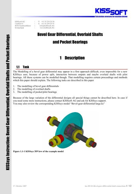
The Modelling of a bevel gear differential may appear in a first approach difficult, even impossible for a new<br />
KISSsys user, because of power split, interaction between outputs <strong>and</strong> maybe overlaid shafts with pilot<br />
bearings. All these systems can be modelled though. That modelling requires certain proceedings <strong>and</strong> methods<br />
which this paper should explain. The following tasks are described in this paper<br />
1. The modelling of bevel gear differentials<br />
2. The modelling of overlaid shafts<br />
3. The modelling of pocket/pilot bearings<br />
Because of the large variation of the differential designs all special things cannot be described here. In case if<br />
you need some more instructions, please contact <strong>KISSsoft</strong> <strong>AG</strong> <strong>and</strong> ask for KISSsys support.<br />
You may also review the corresponding KISSsys model “<strong>Bevel</strong>-gear-differential-large.ks”<br />
Figure 1.1-1 KISSsys 3DView of the example model<br />
17. Oktober 2007 ins-203-01-<strong>Bevel</strong>-gear-differential-shaft-connections 1 / 12
1.2 Schematic<br />
The example model enables to describe these three above problems all in one model:<br />
Figure 1.2-1 Schematic of the example model<br />
2 Modelling<br />
In order to be able to model the correct tree structure the systematic modeling of the above mentioned problems<br />
has to be explained.<br />
2.1 <strong>Overlaid</strong> <strong>Shafts</strong> <strong>and</strong> <strong>Pocket</strong> Bearings<br />
The current problem contains shaft “s2” which is supported by the two shafts “s3” <strong>and</strong> “s4” (overlaid shafts). In<br />
their turn they have each a fixed bearing on the casing, “s4” is assembled in “s3” <strong>and</strong> two bearings (pilot<br />
bearings) between the bore of “s4” <strong>and</strong> the outside diameter of “s3” guarantee that a different movement <strong>and</strong><br />
rotation of the two shafts is possible. Of course shafts “s4” <strong>and</strong> “s3” can also be arranged other way round.<br />
The problem is now the modeling of the force interaction between the three shafts. Just as an example: The gear<br />
force on “z2” has to be supported by the shaft “s2” <strong>and</strong> its bearings, therefore by “s3” <strong>and</strong> “s4”. In its turn, the<br />
deflection of “s3” <strong>and</strong> “s4” will influence the bearings alignment of “s2”. Therefore <strong>KISSsoft</strong> <strong>AG</strong> suggests<br />
modeling the interaction between these three shafts as follows:<br />
Figure 2.1-1 Interaction between overlaid shafts<br />
As indicated by the colors in Figure 2.1-1 the action force “fs2b1” on “s3” is dependant on the bearing force<br />
coming from “b1” on “s2”. In return, the “fs2b1” returns the current deflection of “s3” to “b1” on “s2”. As it is<br />
possible to enter bearing misalignments in <strong>KISSsoft</strong> this value can also be taken into account.<br />
2 / 12
2.2 Modelling with St<strong>and</strong>ard Templates<br />
2.2.1 Forces<br />
The modelling of the interaction between action force <strong>and</strong> bearing is shown as an example between “fs2b1” <strong>and</strong><br />
“b1”. Enter the address of the bearing forces into the expression of the centrical force (example: Fx) to link the<br />
force values to the bearing.<br />
Figure 2.2-1 Defining force from the bearing<br />
Centrical Force Variable Expression<br />
Fx ^.^.s2.b1.Fx<br />
Fy ^.^.s2.b1.Fy<br />
Fz ^.^.s2.b1.Fz<br />
Hint: The sign ^ goes one level up in the three structure <strong>and</strong> gives the path until this level.<br />
Example: ^.^.s2.b1.Fx = GB.s2.b1.Fx<br />
The sign is useful, because you do not have to think less about the address of your variables <strong>and</strong> renaming<br />
after model building is less of a problem.<br />
2.2.2 Deflection<br />
Enter the deflection of the shaft where the centrical load is situated (s3) as offsets (ux, uz) into the bearing<br />
element.<br />
Figure 2.2-2 Bearing offset equals to shaft deflection<br />
3 / 12
As the deflection of the shaft is given in a variable of type point <strong>and</strong> the bearing offset is given as real. It is<br />
possible to take out coordinates of points by multiplying them with the axis you need:<br />
Bearing Variable Expression<br />
ucx ^.^.s3.Fs2b1.deflection*{1,0,0}<br />
ucz ^.^.s3.Fs2b1.deflection*{0,0,1}<br />
2.2.3 Positioning the force<br />
As a last point the force has to be positioned correctly by h<strong>and</strong> or you may create expression between bearing<br />
position <strong>and</strong> force position. If bearing is moved on the shaft force will be automatically repositioned according<br />
to the bearing, because the bearing “b1” <strong>and</strong> the corresponding force “fs2b1” needs to be on the same position in<br />
the space. We can create an expression for the force position, so that it will always be positioned according to<br />
the bearing. This can be done under “Properties”- “position” of the force “fs2b1”.<br />
Figure 2.2-3 Position of the force<br />
Using the function “l_p(reference,{point})*{0,1,0}” it is possible to transform the local coordinate of the<br />
“reference” component to the local coordinate of the parent component of the current component. So taking the<br />
local coordinate of the “b1” on the shaft “s2” <strong>and</strong> transforms it to the local coordinates to of the “fs2b1” on the<br />
shaft “s3”. And finally multiplication with {0,1,0}takes only the y-component.<br />
2.2.4 Notes<br />
Please pay attention to following points when using st<strong>and</strong>ard templates. The orientation <strong>and</strong> direction of the<br />
centrical force <strong>and</strong> the bearing offset have to be identical on both elements. The coordinate systems of the two<br />
elements may not be oriented identical therefore the user has to spend some thoughts about the orientation topic.<br />
2.3 Modelling with Special Templates<br />
<strong>KISSsoft</strong> <strong>AG</strong> has developed special templates to make previously described connections easier. These templates<br />
are also available for our clients. The special templates do the above mentioned steps for force <strong>and</strong> deflection<br />
linkage automatically. See also instructions “ins-303-01-Pilot-bearing.pdf” for the issue.<br />
1. Open the template file “SpecialTemplates.ks”<br />
2. Enter the element “RollerBearingWithDeflections” instead of the normal “kSysRollerBearings” for the<br />
pilot bearings into your tree structure.<br />
3. Enter the element “CentricalLoadWithBearingForces” instead of the normal “kSysCentricalLoad” for<br />
the forces into your tree structure<br />
4. Open the “ForceSelection” of the bearings you entered <strong>and</strong> choose the linked force.<br />
4 / 12
Figure 2.3-1 Choose the connected force<br />
Please pay attention to following points when using the special templates. The positioning <strong>and</strong> orientation of the<br />
elements is correctly translated from one coordinate system to the other, so you do not have to bother with that.<br />
This requires though a correct global positioning of the entities.<br />
2.4 Pilot bearing Calculations<br />
2.4.1 Using st<strong>and</strong>ard bearing calculations<br />
The bearing calculation is always taking the global speed of the shaft where the bearing is situated on. This does<br />
not apply when the inner ring <strong>and</strong> the outer ring are both turning. Then the rotation speed of the bearing has to<br />
be modified in order to take this into account (example “s2b1”):<br />
n = n − n<br />
s2b1<br />
s2<br />
s3<br />
Default expression for the bearing speed can be deleted <strong>and</strong> it needs to be replaced with new expression to get<br />
relative speed between the shafts “s2” <strong>and</strong> “s3”. Expression is “abs(GB.s2.speed-GB.s3.speed)”.<br />
This leads also to the problem, that the speed of the first <strong>and</strong> the second bearing on every of those 3 shafts (s2,<br />
s3 <strong>and</strong> s4) is different. Therefore you have to insert instead of the calculation element “Bearing2” the element<br />
“Bearing1”. It is recommended to insert it under the machine element bearing.<br />
Figure 2.4-1 Bearing speed correction<br />
2.4.2 Using special templates<br />
<strong>KISSsoft</strong> <strong>AG</strong> has developed special templates to make previously described “pilot” bearing speed definition<br />
automatically. These templates are also available for our clients. The special templates do the above mentioned<br />
steps for the speed correction automatically.<br />
1. Open the template file “SpecialTemplates.ks”<br />
5 / 12
2. Enter the element “Pilot_Bearing1” instead of the normal “Bearing1” for the pilot bearings into your<br />
tree structure.<br />
3. “Dialog” to select references is automatically opened.<br />
4. If you want to change definitions, open the “Dialog” of the bearing calculation <strong>and</strong> choose new<br />
references.<br />
Figure 2.4-2 Defining references for the bearing inner <strong>and</strong> outer race<br />
2.5 Example model<br />
Both of the explained methods has been used in the related example model “<strong>Bevel</strong>-gear-differential-large.ks”.<br />
Connections between “s2” <strong>and</strong> “s3” are created using default templates “templates.ks” <strong>and</strong> connections between<br />
shafts “s2 <strong>and</strong> “s4” are made with using “SpecialTemplates.ks”.<br />
2.6 Kinematics Iteration<br />
As the bearing forces are in this case affecting deflection of the shaft <strong>and</strong> the deflection of the shaft in return is<br />
affecting the bearing forces, iterations have to be made when calculating the correct forces. These iterations are<br />
not activated per default.<br />
To activate iterations, right click on “System” <strong>and</strong> choose “Properties”. Check the variable<br />
“kSysKinematicFunc”. Select from the list the functionality “call ‘OnCalcTorque’ during calculation of torque”<br />
<strong>and</strong> quit the window.<br />
Figure 2.6-1 Setting the kinematic iteration<br />
Be informed that you see the iteration steps now in the message bar in the lower section of the KISSsys window<br />
when you are calculating kinematics <strong>and</strong> that the calculation itself takes longer.<br />
6 / 12
The iterations are for the speed <strong>and</strong> torque not activated as per default. To activate iterations, right click on<br />
“System” <strong>and</strong> choose “Properties”. Check the variable “kSysKinematicMode”. Select “iteration for speed <strong>and</strong><br />
torque” from the list. The model may work correctly even without this iteration method, but when model gets<br />
more complicated this iteration is needed.<br />
Figure 2.6-2 Select iteration method for the kinematic calculation<br />
2.7 Model specialties<br />
The following chapters explain special arrangements needed for the differential modelling.<br />
2.7.1 “Carrier” definition<br />
You need one extra component to the model to tell the program how differential gears are connected to the<br />
housing <strong>and</strong> which shaft is the differential housing <strong>and</strong> also how many differential planets are in the model. To<br />
do this, use “kSysPlanetCarrierCoupling” from the templates. This component defines the configuration of the<br />
differential.<br />
Figure 2.7-1 <strong>Differential</strong> carrier component<br />
After you have places this component in to your model on your differential housing “s2” you can define number<br />
of planets in differential by selecting “properties” for that component <strong>and</strong> changing the value for the variable<br />
“NofPlanets”. If you change the number of the planets you need to “updateShaftElements” to consider new<br />
number of the planets for the calculations.<br />
7 / 12
Figure 2.7-2 Changing the number of differential planets<br />
Note! In case if you are using old templates where this component is not present, you can use “kSysCoupling”<br />
component instead <strong>and</strong> add needful information in it. Create new variable “NofPlanets” in the component <strong>and</strong> it<br />
has the same functionality. Remember to add flags for both directions.<br />
Figure 2.7-3 If using "kSysCoupling" add a new Real variable called "NofPlanets"<br />
2.7.2 <strong>Differential</strong> gear connections<br />
Use “ kSysPlanetary<strong>Bevel</strong><strong>Gear</strong>Constraint” to define connections between differential bevel gears. You need to<br />
define first configuration from the list “gear/planet” or “planet/gear”. First gear in the definition is the “gear 1”<br />
<strong>and</strong> second is the “gear 2”. You need to make the selection so that the first gear has less number of teeth. From<br />
the configuration “gear” means the output gear <strong>and</strong> “planet” means the gear connected to the differential<br />
housing. You need to also define which coupling is the “planet carrier”. The layout of the machine elements in<br />
the tree structure is very similar to a planetary gear stage (“cDiff” is in this case the carrier coupling). To<br />
constrain the differential system, choose the “kSysPlanetary<strong>Bevel</strong><strong>Gear</strong>Constraint” from the templates <strong>and</strong> copy<br />
it into the tree structure directly under the group of your model. Constrain the gears as follows.<br />
8 / 12
Figure 2.7-4 Choose differential gear connections<br />
3.1 Positioning according to bevel gears<br />
3 <strong>Gear</strong> positioning<br />
To be able to make “kinematic” calculation user needs to define correct directions <strong>and</strong> positions of the output<br />
shafts in the space, because otherwise it is not possible to define output speeds <strong>and</strong> torques to the correct<br />
directions <strong>and</strong> error in “kinematic” calculation will appear. <strong>Differential</strong> gears needs to be therefore be defined<br />
according to each other, so that correct speeds can be defined for all the shafts.<br />
It is recommended to define first the position of the differential housing “s2”. Then define other of the outputs<br />
“s3” or “s4” to be parallel to the “s2”. Then define differential planet “sd” position according to the differential<br />
gear meshing with gear in the defined shaft <strong>and</strong> finally define the direction <strong>and</strong> position of the other shaft<br />
meshing with the differential planet gear. Use dialog for all shaft to make the positioning<br />
Figure 3.1-1 Choose "dialog" function from the tree to define position for the shafts<br />
For the bevel gear connection choose “According <strong>Bevel</strong> <strong>Gear</strong>s” from the list<br />
9 / 12
Figure 3.1-2 Choose correct positioning method from the list<br />
1) Define the position of the “s2” “According <strong>Bevel</strong> <strong>Gear</strong>s”. Select mating gear <strong>and</strong> define also correct contact<br />
angle.<br />
Figure 3.1-3 Positioning of the shaft "s2" according to the bevel gear mesh “z2” <strong>and</strong> “z1“<br />
2) Define “s4” position to be parallel to “s2”<br />
Figure 3.1-4 Right output "s4" defined parallel to differential housing "s2"<br />
3) Define differential planet “sd” according to mating bevel gear in shaft “s4”<br />
Figure 3.1-5 Planet shaft defined according to bevel gear mesh<br />
4) Finally define direction <strong>and</strong> position of the left output “s3” according to bevel gear mesh with planet gear.<br />
Figure 3.1-6 Left output "s3" defined according to bevel gear mesh<br />
10 / 12
4.1 Input<br />
4 Boundary conditions<br />
Because there are six conditions to define for inputs <strong>and</strong> outputs (speed + torque/power), we need to define three<br />
of them to be able to run calculation. Speed <strong>and</strong> torque definition of a bevel gear differential has to be made<br />
correctly <strong>and</strong> usually Input is totally defined <strong>and</strong> output is then calculated.<br />
Figure 4.1-1 Input fully constrained<br />
4.2 Outputs<br />
That leaves the state of the two outputs undefined. One used option would be the definition of the speed of one<br />
differential output (example: s3) related to the casing speed with a factor k:<br />
n<br />
k =<br />
n<br />
s3<br />
s2<br />
This makes it possible to define a formula for the calculation of the left output speed in our model as follows:<br />
n = n = kn<br />
outl<br />
s3<br />
s2<br />
Definition of the output in the example model has to be made as follows:<br />
1. Definition of global variable k<br />
2. Setting the “kSysSpeedOrForce” element of the left output to “Speed constrained: yes”<br />
3. Entering the expression for the correct speed calculation into the variable “speed” of the<br />
“kSysSpeedOrForce” element of the left output.<br />
Figure 4.2-1 Define new variable "k"<br />
11 / 12
Figure 4.2-2 Constrain the speed value<br />
Figure 4.2-3 Make expression for the "OutL" speed<br />
Attention: Expressions of the element variables are deleted every time you open the dialog of a<br />
“kSysSpeedOrForce”.<br />
5.1 <strong>Differential</strong> bevel gears<br />
5 Calculations<br />
Recommended calculation method for the bevel gears in differential arrangement is “Static calculation”. This<br />
means that even if there is some speed difference inside the differential calculation is based on the static<br />
calculation with maximum possible torque. This torque needs to be defined manually for the calculations <strong>and</strong> is<br />
snot taken from the values in KISSsys.<br />
5.2 “Simplification”<br />
In case if you are not interested any calculations inside differential, it is recommended not to model it at all, but<br />
to use even more simplified method considering differentials as black box <strong>and</strong> to divide only torque between<br />
two outputs having equal speed.<br />
12 / 12