Wavefront Sculpture Technology - R+R Sonicdesign AG
Wavefront Sculpture Technology - R+R Sonicdesign AG
Wavefront Sculpture Technology - R+R Sonicdesign AG

You also want an ePaper? Increase the reach of your titles
YUMPU automatically turns print PDFs into web optimized ePapers that Google loves.
ENGINEERING REPORTS WAVEFRONT SCULPTURE TECHNOLOGY<br />
adapted sound field radiated by a variable-curvature line<br />
source having αd constant is termed a pseudocylindrical<br />
sound field. Shaping the line source array in such a way so<br />
that αd = constant is considered as corresponding to an<br />
additional WST criterion, and the method of adapting the<br />
sound field to the audience geometry in this manner is<br />
termed <strong>Wavefront</strong> <strong>Sculpture</strong>.<br />
6.2 Limits on the Angular Incrementation of a<br />
Curved Line Source<br />
The effect of discontinuities on line source arrays was<br />
investigated in Section 3. Another consideration for a<br />
variable-curvature line source array is the amount of angular<br />
separation that is allowed between two discrete sources<br />
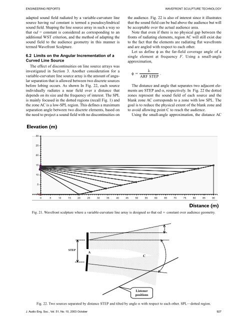
before lobing occurs. As shown In Fig. 22, each source<br />
individually radiates a near field over a distance that<br />
depends on its size and the frequency of interest. The SPL<br />
is mainly focused in the dotted regions (recall Fig. 1) and<br />
the zone AC is a low-SPL region. This defines a maximum<br />
separation angle between two discrete elements, based on<br />
the need to project a sound field with no discontinuities on<br />
Elevation (m)<br />
30<br />
25<br />
20<br />
15<br />
10<br />
5<br />
0<br />
STEP<br />
A<br />
the audience. Fig. 22 is also of interest since it illustrates<br />
that the sound field can be bad above the audience but will<br />
be acceptable over the actual audience area.<br />
Note that even if there is no physical gap between the<br />
fronts of radiating elements, region AC will still exist due<br />
to the fact that the elements are radiating flat wavefronts<br />
and are angled with respect to each other.<br />
Let us define φ as the far-field coverage angle of a<br />
single element at frequency F. Using a small-angle<br />
approximation,<br />
φ<br />
λ<br />
�<br />
ARF STEP<br />
.<br />
The distance and angle that separates two adjacent elements<br />
are STEP and α, respectively. In Fig. 22 the dotted<br />
zones represent the sound field of each source and the<br />
blank zone AC corresponds to a zone with low SPL. The<br />
goal is to reduce the physical extent of the blank zone and<br />
to avoid allowing point C to reach the audience.<br />
Using the small-angle approximation, the distance AC<br />
0 5 10 15 20 25 30 35 40 45 50 55 60 65 70 75 80 85 90<br />
Fig. 21. <strong>Wavefront</strong> sculpture where a variable-curvature line array is designed so that αd � constant over audience geometry.<br />
Listener<br />
positions<br />
Fig. 22. Two sources separated by distance STEP and tilted by angle α with respect to each other. SPL—dotted region.<br />
J. Audio Eng. Soc., Vol. 51, No. 10, 2003 October 927<br />
C<br />
�<br />
�<br />
Distance (m)