Wavefront Sculpture Technology - R+R Sonicdesign AG
Wavefront Sculpture Technology - R+R Sonicdesign AG
Wavefront Sculpture Technology - R+R Sonicdesign AG

You also want an ePaper? Increase the reach of your titles
YUMPU automatically turns print PDFs into web optimized ePapers that Google loves.
ENGINEERING REPORTS WAVEFRONT SCULPTURE TECHNOLOGY<br />
So we require that<br />
� λ<br />
S<br />
4<br />
.<br />
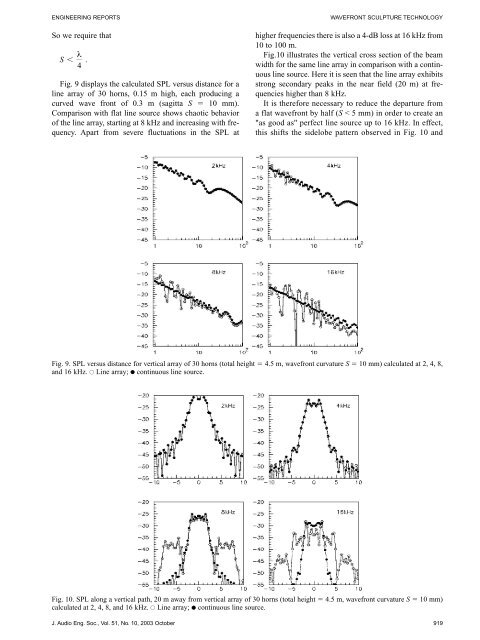
Fig. 9 displays the calculated SPL versus distance for a<br />
line array of 30 horns, 0.15 m high, each producing a<br />
curved wave front of 0.3 m (sagitta S � 10 mm).<br />
Comparison with flat line source shows chaotic behavior<br />
of the line array, starting at 8 kHz and increasing with frequency.<br />
Apart from severe fluctuations in the SPL at<br />
higher frequencies there is also a 4-dB loss at 16 kHz from<br />
10 to 100 m.<br />
Fig.10 illustrates the vertical cross section of the beam<br />
width for the same line array in comparison with a continuous<br />
line source. Here it is seen that the line array exhibits<br />
strong secondary peaks in the near field (20 m) at frequencies<br />
higher than 8 kHz.<br />
It is therefore necessary to reduce the departure from<br />
a flat wavefront by half (S < 5 mm) in order to create an<br />
"as good as" perfect line source up to 16 kHz. In effect,<br />
this shifts the sidelobe pattern observed in Fig. 10 and<br />
Fig. 9. SPL versus distance for vertical array of 30 horns (total height � 4.5 m, wavefront curvature S � 10 mm) calculated at 2, 4, 8,<br />
and 16 kHz. ● Line array; ● continuous line source.<br />
Fig. 10. SPL along a vertical path, 20 m away from vertical array of 30 horns (total height � 4.5 m, wavefront curvature S � 10 mm)<br />
calculated at 2, 4, 8, and 16 kHz. ● Line array; ● continuous line source.<br />
J. Audio Eng. Soc., Vol. 51, No. 10, 2003 October 919