Wavefront Sculpture Technology - R+R Sonicdesign AG
Wavefront Sculpture Technology - R+R Sonicdesign AG
Wavefront Sculpture Technology - R+R Sonicdesign AG

You also want an ePaper? Increase the reach of your titles
YUMPU automatically turns print PDFs into web optimized ePapers that Google loves.
URBAN ET AL. ENGINEERING REPORTS<br />
the on-axis behavior observed in Fig. 9 from 8 to 16 kHz.<br />
We conclude by stating that the deviation from a flat<br />
wavefront should be less than λ/4 at the highest operating<br />
frequency (corresponding to 5 mm at 16 kHz).<br />
4 SOUND FIELD RADIATED BY A FLAT LINE<br />
SOURCE ARRAY<br />
4.1 Radiation as a Function of Distance<br />
For the case of a flat line source array we now consider<br />
the near-field (cylindrical wave propagation) and far-field<br />
(spherical wave propagation) regions and apply Fresnel<br />
analysis to derive an expression for the border distance<br />
between them. The results obtained can be compared with<br />
the analytical calculations presented in [1].<br />
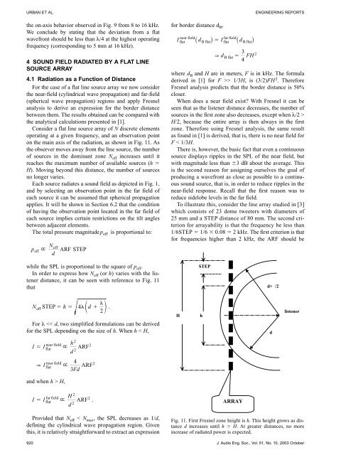
Consider a flat line source array of N discrete elements<br />
operating at a given frequency, and an observation point<br />
on the main axis of the radiation, as shown in Fig. 11. As<br />
the observer moves away from the line source, the number<br />
of sources in the dominant zone Neff increases until it<br />
reaches the maximum number of available sources (h �<br />
H). Moving beyond this distance, the number of sources<br />
no longer varies.<br />
Each source radiates a sound field as depicted in Fig. 1,<br />
and by selecting an observation point in the far field of<br />
each source it can be assumed that spherical propagation<br />
applies. It will be shown in Section 6.2 that the condition<br />
of having the observation point located in the far field of<br />
each source implies certain restrictions on the tilt angles<br />
between adjacent elements.<br />
The total pressure magnitude peff is proportional to:<br />
Neff<br />
p eff " ARF STEP<br />
d<br />
while the SPL is proportional to the square of p eff .<br />
In order to express how N eff (or h) varies with the listener<br />
distance, it can be seen with reference to Fig. 11<br />
that<br />
�<br />
Neff STEP � h � 4�<br />
ed � o .<br />
2<br />
For λ H,<br />
far field<br />
� flat<br />
I I<br />
"<br />
h<br />
d<br />
2<br />
2<br />
4<br />
3Fd<br />
H<br />
d<br />
2<br />
2<br />
ARF<br />
2<br />
ARF<br />
ARF<br />
2<br />
2<br />
.<br />
Provided that N eff < N max , the SPL decreases as 1/d,<br />
defining the cylindrical wave propagation region. Given<br />
this, it is relatively straightforward to extract an expression<br />
for border distance d B ,<br />
near field<br />
flat<br />
far field<br />
B flat flat<br />
I _d i � I _d<br />
i<br />
B flat<br />
3<br />
& dBflat � FH<br />
4<br />
where d B and H are in meters, F is in kHz. The formula<br />
derived in [1] for F >> 1/3H, is (3/2)FH 2 . Therefore<br />
Fresnel analysis predicts that the border distance is 50%<br />
closer.<br />
When does a near field exist? With Fresnel it can be<br />
seen that as the listener distance decreases, the number of<br />
sources in the first zone also decreases, except when λ/2 ><br />
H/2, because the entire array is then always in the first<br />
zone. Therefore using Fresnel analysis, the same result<br />
as found in [1] is derived, that is, there is no near field for<br />
F < 1/3H.<br />
There is, however, the basic fact that even a continuous<br />
source displays ripples in the SPL of the near field, but<br />
with magnitude less than �3 dB about the average. This<br />
is the second reason for assigning ourselves the goal of<br />
producing a wavefront as close as possible to a continuous<br />
sound source, that is, in order to reduce ripples in the<br />
near-field response. Recall that the first reason was to<br />
reduce sidelobe levels in the far field.<br />
To illustrate this, consider the line array studied in [3]<br />
which consists of 23 dome tweeters with diameters of<br />
25 mm and a STEP distance of 80 mm. The second criterion<br />
for arrayability is that the frequency be less than<br />
1/6STEP � 1/6 � 0.08 � 2 kHz. The first criterion is that<br />
for frequencies higher than 2 kHz, the ARF should be<br />
920 J. Audio Eng. Soc., Vol. 51, No. 10, 2003 October<br />
H<br />
STEP<br />
h<br />
ARRAY<br />
Fig. 11. First Fresnel zone height is h. This height grows as distance<br />
d increases until h � H. At greater distances, no more<br />
increase of radiated power is expected.<br />
2<br />
d+�/2<br />
d<br />
listener