Wavefront Sculpture Technology - R+R Sonicdesign AG
Wavefront Sculpture Technology - R+R Sonicdesign AG
Wavefront Sculpture Technology - R+R Sonicdesign AG

You also want an ePaper? Increase the reach of your titles
YUMPU automatically turns print PDFs into web optimized ePapers that Google loves.
URBAN ET AL. ENGINEERING REPORTS<br />
is given by<br />
STEP<br />
AC �<br />
2φ<br />
� α<br />
.<br />
Rewriting φ in terms of frequency and specifying that AC<br />
is smaller than d,<br />
2 STEP<br />
α �<br />
� .<br />
3F<br />
ARF STEP d<br />
Where α is in radians, F in kHz, and STEP in meters. It<br />
is required that α be greater than zero. Thus,<br />
STEP �<br />
2d<br />
.<br />
3F<br />
ARF<br />
The worst case is for F � 16 kHz and d � d min , the minimum<br />
distance where a listener will be located. This corresponds<br />
to<br />
STEP<br />
max<br />
�<br />
d min<br />
.<br />
24 ARF<br />
Substituting STEP max in the above expression for α we get<br />
the following expression for the maximum tilt angle α max ,<br />
α<br />
max<br />
R<br />
2 V<br />
STEP STEP S J<br />
STEP<br />
N W<br />
max max<br />
� S1<br />
� K O<br />
d min STEP K STEP O<br />
W<br />
S L max P W<br />
T<br />
X<br />
R<br />
2 V<br />
1 1 S J<br />
STEP<br />
N W<br />
� S1<br />
� K O .<br />
24ARF<br />
STEP K STEP O<br />
W<br />
S L max P W<br />
T<br />
X<br />
From this expression it is seen that there is a tradeoff<br />
between the maximum element size and the maximum<br />
allowable interelement angles, that is, in order to increase<br />
the angles between sources, the element size must be<br />
reduced.<br />
As an example, consider a minimum listener distance d min<br />
equal to 10 m. Since the diameter of a 15 in low-frequency<br />
component is typically 0.40 m, this implies a minimum<br />
STEP of 0.44 m when allowing for the additional thickness<br />
of the loudspeaker enclosure walls. Given this mini-<br />
mum STEP value, the maximum tilt angle α max becomes<br />
α<br />
max<br />
57 . �<br />
� � 26 . � .<br />
ARF<br />
Since ARF must remain between 0.8 and 1, therefore α max<br />
will be between 4.5º and 3.1º, which represents the maximum<br />
allowable angle between enclosures. Additional<br />
results are tabulated for a variety of component values in<br />
Table 1.<br />
The intensity can be expressed as<br />
2<br />
4 1 ARF<br />
I �<br />
.<br />
3 Fd αd<br />
1 �<br />
STEP<br />
Assuming a STEP of 0.44 m, d min of 10 m, and a frequency<br />
of 16 kHz, it is found that αd/STEP is of order 1.<br />
Therefore the intensity will be roughly a factor of 2<br />
smaller (�3 dB) than the on-axis intensity for a flat array<br />
(α � 0).<br />
7 CONCLUSION<br />
The Fresnel approach in optics has been applied to<br />
acoustics in order to understand and characterize the<br />
sound field radiated by linear arrays. Fresnel analysis does<br />
not provide precise numerical results but gives a semiquantitative,<br />
intuitive understanding. More precise results<br />
must be obtained using numerical analysis techniques.<br />
However, Fresnel analysis allows one to predict the<br />
answers in a semiquantitative way.<br />
The problem of defining when an assembly of discrete<br />
sources can be considered as equivalent to a continuous<br />
line source was addressed, and the reasons why a continuous<br />
line source is desirable were also presented. It was<br />
seen that a continuous line source exhibits two different<br />
regimes: when close to the source the SPL varies as 1/d<br />
(cylindrical wave propagation) and far away the SPL<br />
varies as 1/d 2 (spherical wave propagation). The position<br />
of the border between these two regimes is proportional to<br />
the frequency and to the square of the height of the array.<br />
In addition, for low enough frequencies there is no near<br />
field.<br />
By studying the properties of curved arrays using<br />
Fresnel analysis, the conditions concerning the tilt angles<br />
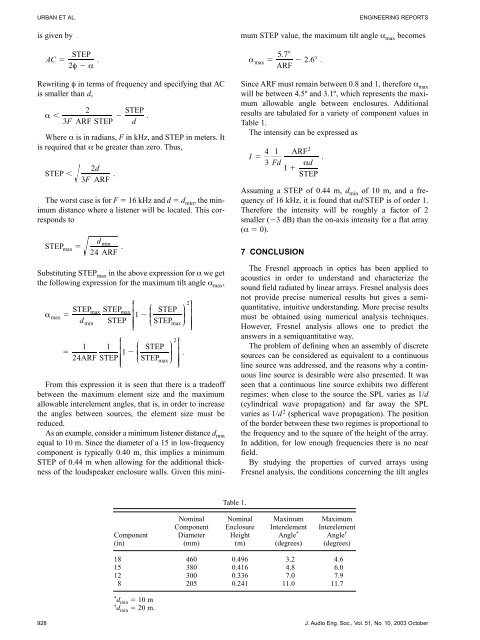
Nominal Nominal Maximum Maximum<br />
Component Enclosure Interelement Interelement<br />
Component Diameter Height Angle * Angle †<br />
(in) (mm) (m) (degrees) (degrees)<br />
18 460 0.496 3.2 4.6<br />
15 380 0.416 4.8 6.0<br />
12 300 0.336 7.0 7.9<br />
8 205 0.241 11.0 11.7<br />
* dmin � 10 m<br />
† dmin � 20 m.<br />
Table 1.<br />
928 J. Audio Eng. Soc., Vol. 51, No. 10, 2003 October