

Instructions for the Digitrip RMS 310 3-Pole and 4 ... - Eaton Canada
Instructions for the Digitrip RMS 310 3-Pole and 4 ... - Eaton Canada
Instructions for the Digitrip RMS 310 3-Pole and 4 ... - Eaton Canada

You also want an ePaper? Increase the reach of your titles
YUMPU automatically turns print PDFs into web optimized ePapers that Google loves.
Table of Contents<br />
<strong>Instructions</strong> <strong>for</strong> <strong>the</strong> <strong>Digitrip</strong> <strong>RMS</strong> <strong>310</strong> 3-<strong>Pole</strong> <strong>and</strong> 4-<strong>Pole</strong> Trip Unit Installation<br />
<strong>and</strong> Operation with L-Frame <strong>and</strong> MDL-Frame Series C Circuit Breakers<br />
Description Page<br />
1 .O General In<strong>for</strong>mation ............................................... 1<br />
1.1 Protection .............................................................. 1<br />
2.0 UL Listed Devices .................................................. 2<br />
3.0 Installation ............................................................. 2<br />
3.1 Preparation (All Trip Units) ..................................... 2<br />
3.2 4-<strong>Pole</strong> Trip Unit Installation ..................................... 2<br />
3.3 Ground Fault Trip Unit Installation .......................... 3<br />
3.3.1 General .................................................................. 3<br />
3.3.2 Installation ............................................................. 3<br />
3.4<br />
3.5<br />
4.0<br />
4.1<br />
4.2<br />
4.3<br />
4.4<br />
5.0<br />
5.1<br />
5.2<br />
5.3<br />
5.4<br />
5.5<br />
5.6<br />
6.0<br />
6.1<br />
6.2<br />
3-<strong>Pole</strong> (Non-Ground Fault) Trip Unit Installation ..... 5<br />
Final Installation <strong>Instructions</strong> (All Trip Units) ........... 6<br />
Principle of Operation ............................................ 6<br />
General .................................................................. 7<br />
Overload Trip ......................................................... 7<br />
Short Delay/lnstantaneous Trip .............................. 7<br />
Ground Fault Protection ......................................... 7<br />
Protection Settings ................................................. 7<br />
General .................................................................. 7<br />
Short Delay Pick-up Settings ................................. 7<br />
Short Delay Time Settings ..................................... 7<br />
Instantaneous Pickup Setting ................................ 7<br />
Ground Fault Pick-up Setting ................................. 7<br />
Ground Fault Time Settings ................................... 8<br />
Testing ................................................................... 8<br />
Functional Field Testing ......................................... 8<br />
Per<strong>for</strong>mance Testing - <strong>for</strong> Ground Fault Trip Units .... 8<br />
6.2.1 Code Requirements ............................................... 8<br />
6.2.2 St<strong>and</strong>ards Requirements .......................................<br />
6.2.3 General Test <strong>Instructions</strong> .......................................<br />
9<br />
9<br />
7.0 Rating Plug .......................................................... 12<br />
8.0 References .......................................................... 12<br />
8.1 Series C L-Frame Molded Case<br />
Circuit Breakers ................................................... 12<br />
8.2 Internal Accessories ............................................<br />
A WARNING<br />
12<br />
DEATH, SEVERE PERSONAL INJURY, OR<br />
SUBSTANTIAL PROPERTY DAMAGE CAN RESULT<br />
FROM CONTACT WITH ENERGIZED EQUIPMENT. DO<br />
NOT ATTEMPT INSTALL OR PERFORM<br />
MAINTENANCE ON EQUIPMENT WHILE IT IS<br />
ENERGIZED. ALWAYS VERIFY THAT NO VOLTAGE IS<br />
PRESENT BEFORE PROCEEDING WITHTHETASK,<br />
AND ALWAYS FOLLOW GENERALLY ACCEPTED<br />
SAFETY PROCEDURES.<br />
CUTLER-HAMMER IS NOT LIABLE FORTHE<br />
MISAPPLICATION OR MISINSTALLATION OF ITS<br />
PRODUCTS.<br />
The user is cautioned to observe all recommendations,<br />
warnings, <strong>and</strong> cautions relating to <strong>the</strong> safety of personnel<br />
<strong>and</strong> equipment as well as all general <strong>and</strong> local health <strong>and</strong><br />
safety laws, codes, <strong>and</strong> procedures.<br />
The recommendations <strong>and</strong> in<strong>for</strong>mation contained herein<br />
are based on Cutler-Hammer experience <strong>and</strong> judgement,<br />
but should not be considered to be all-inclusive or covering<br />
every application or circumstance which may arise. If<br />
any questions arise, contact Cutler-Hammer <strong>for</strong> fur<strong>the</strong>r<br />
in<strong>for</strong>mation or instructions.<br />
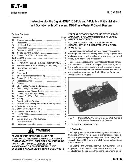
Fig. 1 <strong>Digitrip</strong> <strong>RMS</strong> <strong>310</strong> Trip Unit <strong>for</strong> 3-<strong>Pole</strong> L-Frame &<br />
MDL Frame Series C Circuit Breaker<br />
1 .O GENERAL INFORMATION<br />
I.L. 29C615E<br />
1.1 Protection<br />
The <strong>Digitrip</strong> <strong>RMS</strong> 31 0, illustrated in Figure 1, is an electronic<br />
trip unit that incorporates a microprocessor-based<br />
custom application specific integrated circuit design <strong>for</strong><br />
use with Series C L-Frame <strong>and</strong> MDL Frame Molded Case<br />
Circuit Breakers.<br />
The <strong>Digitrip</strong> <strong>RMS</strong> <strong>310</strong> provides true <strong>RMS</strong> current sensing<br />
<strong>for</strong> proper correlation with <strong>the</strong>rmal characteristics of<br />
conductors <strong>and</strong> equipment. Interchangeable rating plugs<br />
Effective March 2003 Supersedes I.L. 29C615D dated July 1998 EATON
Page 2<br />
are provided to establish <strong>the</strong> continuous current rating of<br />
each circuit breaker.<br />
The <strong>Digitrip</strong> <strong>RMS</strong> <strong>310</strong> Trip Unit is completely self-con-<br />
tained <strong>and</strong> when <strong>the</strong> circuit breaker is closed, requires no<br />
external power to operate its protection systems. It<br />
operates from current signal levels <strong>and</strong> control power<br />
derived through current sensors integrally mounted in <strong>the</strong><br />
trip unit.<br />
<strong>Digitrip</strong> <strong>RMS</strong> 31 0 Trip Units are suitable <strong>for</strong> 50/60 Hz AC<br />
applications only. For DC applications, a <strong>the</strong>rmal-magnetic<br />
trip unit should be used.<br />
The <strong>Digitrip</strong> <strong>RMS</strong> <strong>310</strong> Trip Unit is available in 4 different<br />
types, (see Table 1-1). Each trip unit contains a fixed long<br />
delay time function (adjusted by changing <strong>the</strong> rating plug),<br />
<strong>and</strong> may be equipped with a maximum of two phase <strong>and</strong><br />
two ground (time-current) adjustments to meet specific<br />
application requirements. The types of adjustments<br />
available <strong>for</strong> each model include <strong>the</strong> following:<br />
Adjustment<br />
1) Short Delay Pick-up<br />
2) Short Delay Pick-up/Short Delay Time<br />
3) Short Delay Pick-up/Ground Fault<br />
Pick-up/Ground Fault Time<br />
4) Short Delay Pick-up/Short Delay Time<br />
Ground Fault Pick-up/Ground<br />
Fault Time<br />
Tm<br />
LESxxxLS,-LSE,-LSP<br />
or MESxxxLS<br />
LESXXXLS I, -LS I E, -LS I P<br />
or MESxxxLSl<br />
LESxxxLSG,<br />
or MESxxxLSG<br />
LESxxxLS I G<br />
or MESxxxLSlG<br />
2.0 UL LISTED DEVICES<br />
The <strong>Digitrip</strong> <strong>RMS</strong> <strong>310</strong> Trip Unit is listed in accordance with<br />
Underwriters Laboratories, Inc. St<strong>and</strong>ard UL489, under<br />
File E7819 <strong>and</strong> satisfies <strong>the</strong> applicable requirements of<br />
<strong>the</strong> International Electrotechnical Commission (IEC)<br />
recommendations <strong>for</strong> molded case circuit breakers.<br />
KPlaces)\<br />
Retaining Sensor<br />
Screw<br />
Current<br />
Trip Unit<br />
Retaining<br />
Screw<br />
L Secondary<br />
Winding<br />
Connector<br />
Fig. 2 Preliminary Alignment of Trip Unit <strong>and</strong> Current<br />
Sensor<br />
3 .O INSTAL LATlO N<br />
I.L. 29C615E<br />
3.1 Preparation (AllTrip Units)<br />
The installation procedure consists of inspecting <strong>and</strong><br />
installing <strong>the</strong> trip unit <strong>and</strong> rating plug. To install <strong>the</strong> trip<br />
unit, per<strong>for</strong>m <strong>the</strong> following steps.<br />
Note: If required, internal accessory installation<br />
should be done be<strong>for</strong>e <strong>the</strong> circuit breaker is mounted<br />
<strong>and</strong> connected. Refer to individual accessory instruction<br />
leaflets.<br />
Make sure that <strong>the</strong> trip unit is suitable <strong>for</strong> <strong>the</strong> intended<br />
installation by comparing nameplate data with any<br />
existing equipment <strong>and</strong> system requirements. Inspect <strong>the</strong><br />
trip unit <strong>for</strong> completeness, <strong>and</strong> check <strong>for</strong> damage be<strong>for</strong>e<br />
installing it in <strong>the</strong> circuit breaker frame.<br />
Note:Trip unit center retaining screw is captive in <strong>the</strong><br />
trip unit conductor; <strong>the</strong> remaining retaining screws (2<br />
<strong>for</strong> a 3-pole trip unit, 3 <strong>for</strong> a 4-pole trip unit) are<br />
supplied with <strong>the</strong> frame.<br />
Remove circuit breaker pan-head cover screws, <strong>and</strong> cover.<br />
To continue installation, proceed to <strong>the</strong> section applicable<br />
to <strong>the</strong> trip unit being installed:<br />
Trip UnitTvpe Section<br />
4-pole Type Trip Unit 3.2<br />
3-pole Ground Fault Trip Unit<br />
3.3<br />
3-pole Non-Ground Fault Trip Unit<br />
3.4<br />
3.2 4-<strong>Pole</strong>Trip Unit Installation<br />
Remove <strong>the</strong> three screws <strong>for</strong> <strong>the</strong> left- <strong>and</strong> right-pole <strong>and</strong><br />
fourth pole contact bases (Fig. 3) from <strong>the</strong> hardware bag.<br />
Place <strong>the</strong> trip unit <strong>and</strong> fourth pole current sensor side by<br />
side on a flat surface. (See Fig. 2)<br />
Remove <strong>the</strong> CAUTION tag from <strong>the</strong> current sensor<br />
secondary winding leads.<br />
Note: Secondary winding connector is not polarized.<br />
Plug <strong>the</strong> current sensor secondary winding connector into<br />
<strong>the</strong> receptacle in <strong>the</strong> side of <strong>the</strong> trip unit. Ei<strong>the</strong>r polarity is<br />
acceptable.<br />
Note:The two trip unit outer retaining screws <strong>and</strong><br />
fourth pole sensor retaining screw may be placed in<br />
<strong>the</strong> trip unit conductor holes at this time. If preferred,<br />
<strong>the</strong> 5/16 inch hexagonal-head wrench may be used to<br />
position <strong>the</strong> screws when <strong>the</strong> trip unit is in <strong>the</strong> base.<br />
Position trip unit <strong>and</strong> fourth pole current sensor in base.<br />
Make sure latch bracket pin is properly seated in slots in<br />
side plates (see Fig. 4). If necessary, push circuit breaker<br />
h<strong>and</strong>le towards <strong>the</strong> closed position to help seat trip unit.<br />
Effective March 2003
I.L. 29C615E<br />
Fig. 3 Contact Bases <strong>and</strong> Load Copper<br />
LINE END<br />
Unit LOAD END<br />
Fig. 4 Trip Unit Installed in Circuit Breaker<br />
a CAUTION<br />
-Contact<br />
Base<br />
-Load<br />
Copper<br />
Side<br />
Plate<br />
Trigger<br />
Trip<br />
Unit <strong>and</strong><br />
Current<br />
Sensor<br />
Retaining<br />
Screws<br />
Fourth<br />
. <strong>Pole</strong><br />
Current<br />
Sensor<br />
DO NOT EXCEED ATORQUE OF 12 LB-FT<br />
(16.27 N.M). EXCESSIVETORQUING WILL SHEAR<br />
SCREWS.<br />
FAILURE TO APPLY THE REQUIREDTORQUE MAY<br />
LEAD TO EXCESSIVE HEATING AND CAUSE<br />
NUISANCE TRIPPING OFTHE CIRCUIT BREAKER.<br />
Screw in <strong>and</strong> tighten three trip unit retaining screws<br />
(center first) <strong>and</strong> <strong>the</strong> screw <strong>for</strong> <strong>the</strong> fourth pole current<br />
sensor.Torque to 12 Ib-ft (16.27 N.m) (see Fig. 4).<br />
Finish installation of <strong>the</strong> 4-pole Trip Unit by following <strong>the</strong><br />
instructions in Section 3.5.<br />
3.3 Ground FaultTrip Unit Installation<br />
3.3.1 General<br />
Page 3<br />
Ground fault trip units are supplied from <strong>the</strong> factory with a<br />
wire harness with pigtail lead connections <strong>for</strong> a neutral<br />
current sensor (white <strong>and</strong> grey wires) <strong>and</strong> a ground fault<br />
alarm relay (yellow <strong>and</strong> green wires). A neutral current<br />
sensor is provided with each trip unit, <strong>and</strong> <strong>the</strong> ground fault<br />
alarm relay is ordered <strong>and</strong> shipped separately if required.<br />
If <strong>the</strong> alarm relay is not required, <strong>the</strong> green <strong>and</strong> yellow<br />
leads should be cut off be<strong>for</strong>e <strong>the</strong> trip unit is installed in<br />
<strong>the</strong> breaker.<br />
<strong>Digitrip</strong> <strong>RMS</strong> 31 0 Ground Fault Trip Units detect ground<br />
fault currents through Residual Sensing. They are not<br />
designed to use source ground or zero sequence ground<br />
fault sensing methods. If <strong>the</strong> system neutral is grounded,<br />
but no phase to neutral loads are used, <strong>the</strong> neutral current<br />
sensor is not necessary. In that case, <strong>the</strong> white <strong>and</strong> grey<br />
leads on <strong>the</strong> trip unit should be cut off be<strong>for</strong>e installation.<br />
If <strong>the</strong> system neutral is grounded <strong>and</strong> phase to neutral<br />
loads are used, <strong>the</strong>n <strong>the</strong> neutral current sensor (see Fig. 5)<br />
must be used. It should be connected to <strong>the</strong> breaker<br />
according to <strong>the</strong> diagram in Fig. 6. It has <strong>the</strong> same turns<br />
ratio as <strong>the</strong> phase current sensors in <strong>the</strong> trip unit.<br />
Note: The polarity of <strong>the</strong> sensor connections is<br />
critical. Always observe <strong>the</strong> polarity markings on <strong>the</strong><br />
installation drawings. The polarity markings are<br />
identified as white dots on <strong>the</strong> trans<strong>for</strong>mer.To insure<br />
correct ground fault equipment per<strong>for</strong>mance, conduct<br />
field tests to comply with National Electric Code<br />
requirements under article 230-95(C). See Section 6.2<br />
<strong>for</strong> testing instructions.<br />
The optional “Internal Accessories” listed in Section 8.2<br />
are available <strong>for</strong> installation in a <strong>Digitrip</strong> <strong>RMS</strong> 31 0 Ground<br />
Fault Trip Unit.These items, if required, must be ordered<br />
separately.<br />
3.3.2 Installation<br />
Plug <strong>the</strong> wire harness supplied <strong>for</strong> <strong>the</strong> neutral current<br />
sensor <strong>and</strong> ground fault alarm relay (white, grey, yellow<br />
<strong>and</strong> green wires) into <strong>the</strong> connector located in <strong>the</strong> right<br />
pole of <strong>the</strong> trip unit. With <strong>the</strong> correct polarity <strong>the</strong> harness<br />
should snap into place. Do not <strong>for</strong>ce <strong>the</strong> harness into <strong>the</strong><br />
connector with <strong>the</strong> wrong polarity.<br />
Remove trip unit outer pole screws <strong>and</strong> red plastic<br />
washers from <strong>the</strong> breaker frame. Discard red plastic<br />
washers (fig. 7). For <strong>the</strong> MDL-frame, also remove <strong>the</strong> load<br />
end trip unit mounting screws from <strong>the</strong> frame<br />
(fig. 7a).<br />
Effective March 2003 EAVN
Page 4<br />
Fig. 5<br />
Fig. 6<br />
SOURCE<br />
LOAD<br />
.Aux~Iiary switch shown m <strong>the</strong> "Breaker Canlacis Open'' pmilmn<br />
Fig. 7a MDL Trip Unit Installation<br />
-COVER SCREWS<br />
TORQUE 20-22<br />
9<br />
9<br />
I.L. 29C615E<br />
E:VN Effective March 2003<br />
-1b
I.L. 29C615E<br />
Lefl<br />
Contact<br />
Base<br />
Right<br />
Contact<br />
Base<br />
Fig. 7 Left- <strong>and</strong> Right-<strong>Pole</strong> Contact Bases<br />
Circuit Latch<br />
Breaker<br />
H<strong>and</strong>le<br />
Side Trip Side<br />
Plate Unit Plate<br />
Retaining<br />
Screws<br />
Fig. 8 Trip Unit Installed in Circuit Breaker<br />
Note: The two trip unit outer retaining screws may be<br />
placed in <strong>the</strong> trip unit conductor holes at this time. If<br />
preferred, <strong>the</strong> 5/16 inch hexagonal-head wrench may<br />
be used to position <strong>the</strong> screws when <strong>the</strong> trip unit is in<br />
<strong>the</strong> base.<br />
Page 5<br />
Position trip unit in base. Make sure latch bracket pin is<br />
properly seated in slots in side plates (see Fig. 8). If<br />
necessary, move latch toward load end of circuit breaker<br />
to seat trip unit.<br />
Screw in <strong>and</strong> tighten three trip unit retaining screws<br />
(centerfirst).Torque to 12 Ib-ft (16.27 N.m) (see Fig. 8).<br />
A CAUTION<br />
DO NOT EXCEED ATORQUE OF 12 LB-FT<br />
(16.27 N.m). EXCESSIVE TORQUING WILL SHEAR<br />
SCREWS.<br />
FAILURETO APPLYTHE REQUIREDTORQUE MAY<br />
LEADTO EXCESSIVE HEATING AND CAUSE<br />
NUISANCE TRIPPING OF THE CIRCUIT BREAKER.<br />
For an MDL-frame, also screw in <strong>and</strong> torque <strong>the</strong> load end<br />
screws to 6-8 Ib-ft. (8.14-10.85 N.m.).<br />
3.4 3-<strong>Pole</strong> (Non-Ground Fault) Trip Unit Installation<br />
Remove trip unit outer pole screws <strong>and</strong> red plastic<br />
washers from <strong>the</strong> breaker frame. Discard red plastic<br />
washers (fig. 7). For <strong>the</strong> MDL-frame, also remove <strong>the</strong> load<br />
end trip unit mounting screws from <strong>the</strong> frame<br />
(fig. 7a).<br />
Note: The two trip unit outer retaining screws may be<br />
placed in <strong>the</strong> trip unit conductor holes at this time. If<br />
preferred, <strong>the</strong> 5/16 inch hexagonal-head wrench may<br />
be used to position <strong>the</strong> screws when <strong>the</strong> trip unit is in<br />
<strong>the</strong> base.<br />
Position trip unit in base. Make sure latch bracket pin is<br />
properly seated in slots in side plates (see Fig. 8). If<br />
necessary, move latch toward load end of circuit breaker<br />
to seat trip unit.<br />
Screw in <strong>and</strong> tighten three trip unit retaining screws<br />
(centerfirst).Torque to 12 Ib-ft (16.27 N.m) (see Fig. 8).<br />
A CAUTION<br />
DO NOT EXCEED ATORQUE OF 12 LB-FT<br />
(16.27 n.M). EXCESSIVE TORQUING WILL SHEAR<br />
SCREWS.<br />
FAILURETO APPLYTHE REQUIRED TORQUE MAY<br />
LEADTO EXCESSIVE HEATING AND CAUSE<br />
NUISANCE TRIPPING OF THE CIRCUIT BREAKER.<br />
Effective March 2003 EAVN
Page 6<br />
For an MDL-frame, also screw in <strong>and</strong> torque <strong>the</strong> load end<br />
screws to 6-8 Ib-ft. (8.14-10.85 N.m.)<br />
3.5 Final Installation <strong>Instructions</strong> (All Trip Units)<br />
Install accessory(ies), if required, using <strong>the</strong> appropriate<br />
instruction leaflet listed in Section 8.2. Where accessories<br />
are not required, install protective barriers supplied with<br />
<strong>the</strong> trip unit in accessory retaining slots in left- <strong>and</strong> right-<br />
h<strong>and</strong> poles of trip unit <strong>and</strong> in fourth pole current sensor if<br />
applicable.<br />
Make sure interphase barriers <strong>and</strong> sliding h<strong>and</strong>le barrier<br />
are in place.<br />
Install circuit breaker covers <strong>and</strong> pan-head screws as<br />
shown in Fig. 9.<br />
a CAUTION<br />
THE RATING PLUG MECHANICALLY INTERLOCKS<br />
WITH THE TRIP UNIT. IF THE RATING PLUG IS NOT<br />
CORRECTLY INSTALLED, THE CIRCUIT BREAKER<br />
CANNOT BE RESET OR PLACED IN THE "ON"<br />
POSITION.<br />
.164-32 x<br />
1.75 Lg.<br />
Pan-head<br />
Screw<br />
@ $3<br />
Replace Term. Cover<br />
Fig. 9 Cover Screw Installation Positions<br />
Fourth<br />
Note: Be<strong>for</strong>e attempting to install <strong>the</strong> rating plug, <strong>the</strong><br />
arrow in <strong>the</strong> Push-to-Trip button portion of <strong>the</strong> plug<br />
must be pointing toward <strong>the</strong> REMOVE position.This<br />
can be done with a small screwdriver.<br />
Install rating plug. Position <strong>the</strong> rating plug as shown in Fig.<br />
10. Insert <strong>the</strong> rating plug in <strong>the</strong> trip unit.The pins <strong>and</strong><br />
plunger must align correctly with <strong>the</strong> matching receptacles<br />
<strong>and</strong> slot in <strong>the</strong> trip unit. After <strong>the</strong> rating plug is pressed into<br />
position, depress <strong>the</strong> Push-to-Trip button with a small<br />
screwdriver <strong>and</strong> turn it clockwise one quarter of a turn<br />
until <strong>the</strong> arrow points to ENGAGED. If an adjustable rating<br />
plug is used, four continuous current settings are possible.<br />
Set <strong>the</strong> switch marked A, B, C, D to <strong>the</strong> current rating<br />
desired.<br />
Note: The reverse procedure is used to remove <strong>the</strong><br />
rating plug. Turn <strong>the</strong> Push-to-Trip button to <strong>the</strong><br />
remove position. This action will cause <strong>the</strong> circuit<br />
breaker to trip. Then grasp <strong>the</strong> lip of <strong>the</strong> Push-to-Trip<br />
button <strong>and</strong> gently pull. A small screwdriver placed<br />
under <strong>the</strong> left edge of <strong>the</strong> rating plug will assist in<br />
removal.<br />
Reset circuit breaker by moving h<strong>and</strong>le to <strong>the</strong> reset<br />
position. Move h<strong>and</strong>le to <strong>the</strong> ON position. Circuit breaker<br />
h<strong>and</strong>le should remain at <strong>the</strong> ON position.<br />
Press Push-to-Trip button (in rating plug) to check manual<br />
tripping of <strong>the</strong> circuit breaker.<br />
Trip<br />
Unit<br />
Fig. 10 Installing Rating Plug<br />
4.0 PRINCIPLE OF OPERATION<br />
I.L. 29C615E<br />
In open air at 40ºC, an L-Frame circuit breaker or an<br />
M-Frame circuit breaker with a <strong>Digitrip</strong> <strong>RMS</strong> <strong>310</strong> Trip<br />
Unit installed will carry continuously up to 600 amperes<br />
or 800 amperes respectively without exceeding a<br />
50°C rise at properly sized <strong>and</strong> installed terminations.<br />
The calibration of <strong>the</strong> trip unit is insensitive to<br />
ambient temperatures over a range of -20º to +55ºC.<br />
However, <strong>the</strong> trip unit contains <strong>the</strong>rmal temperature<br />
protective circuitry that initiates a trip operation <strong>for</strong> selfprotection<br />
if <strong>the</strong> internal ambient temperature at <strong>the</strong><br />
printed circuit board (PCB) reaches approximately 100°C.<br />
This may occur <strong>for</strong> open air temperatures above 40°C<br />
with circuit breaker currents near full load.<br />
Effective March 2003
I.L. 29C615E<br />
For ambient conditions above 40°C <strong>and</strong> where <strong>the</strong><br />
maximum ampere rating plug has been installed, derating<br />
of <strong>the</strong> circuit breaker frame should be considered to avoid<br />
exceeding a safe terminal temperature operating range.<br />
Consult Cutler-Hammer <strong>for</strong> recommendations.<br />
4.1 General<br />
The <strong>Digitrip</strong> <strong>RMS</strong> 31 0 Trip Unit provides a tripping signal<br />
to <strong>the</strong> flux transfer shunt trip when current <strong>and</strong> time delay<br />
settings are exceeded. This is accomplished by employing<br />
<strong>the</strong> Cutler-Hammer custom designed integrated circuit<br />
SpreTMchip, which includes a microcomputer to per<strong>for</strong>m<br />
its numeric <strong>and</strong> logic functions.<br />
In <strong>the</strong> <strong>Digitrip</strong> <strong>RMS</strong> 31 0 Trip Unit, all required sensing <strong>and</strong><br />
tripping power to operate its protection function is derived<br />
from <strong>the</strong> current sensors in <strong>the</strong> circuit breaker. The<br />
secondary currents from <strong>the</strong>se sensors provide <strong>the</strong><br />
correct input in<strong>for</strong>mation <strong>for</strong> <strong>the</strong> protection functions, as<br />
well as tripping power, whenever <strong>the</strong> circuit breaker is<br />
carrying current. These current signals develop analog<br />
voltages across <strong>the</strong> appropriate calibrating resistors.<br />
The microcomputer, in cyclic fashion, repeatedly scans<br />
<strong>the</strong> voltage values across each calibrating resistor <strong>and</strong><br />
enters <strong>the</strong>se values into memory. These data are used to<br />
calculate true <strong>RMS</strong> current values, which are <strong>the</strong>n repeatedly<br />
compared with <strong>the</strong> protection function settings <strong>and</strong><br />
o<strong>the</strong>r operating data stored in <strong>the</strong> memory. The software<br />
program <strong>the</strong>n determines whe<strong>the</strong>r to initiate protection<br />
functions, including tripping <strong>the</strong> breaker through <strong>the</strong> flux<br />
transfer shunt trip device in <strong>the</strong> circuit breaker.<br />
4.2 Overload Trip: In accordance with st<strong>and</strong>ards requirements,<br />
<strong>the</strong> trip unit initiates a trip of <strong>the</strong> circuit breaker<br />
within two hours <strong>for</strong> an overload of 135 percent, <strong>and</strong> will<br />
trip in less time <strong>for</strong> higher overload currents.<br />
A “Thermal Memory” effect prevents <strong>the</strong> breaker from<br />
being re-energized immediately after an overload. A<br />
“cooling off” period of up to 5 minutes is required, which<br />
allows time <strong>for</strong> cabling to cool off.<br />
4.3 Short Delay InstantaneousTrip: For short circuit<br />
conditions that exceed <strong>the</strong> short delay pick-up settings,<br />
<strong>the</strong> trip unit initiates a trip after a delay prescribed by <strong>the</strong><br />
I2t ramp function <strong>for</strong> trip units with catalog number suffixes<br />
LS, LSE, LSP, <strong>and</strong> LSG. A flat response time delay action<br />
is provided by trip units with catalog number suffixes LSI,<br />
LSIE, LSIP, <strong>and</strong> LSlG unless <strong>the</strong> instantaneous (I) setting<br />
is selected.<br />
4.4 Ground Fault Protection: When selected, ground<br />
fault pick-up <strong>and</strong> time delay settings shown in Table 1-2<br />
allow selective ground fault coordination with o<strong>the</strong>r circuit<br />
protection devices.<br />
Effective March 2003<br />
CAUTION<br />
Page 7<br />
5.0 PROTECTION SETTINGS<br />
5.1 General<br />
Prior to placing any circuit breaker in operation, each trip<br />
unit protection setting must be set to <strong>the</strong> values specified<br />
by <strong>the</strong> engineer responsible <strong>for</strong> <strong>the</strong> installation. The<br />
available settings along with <strong>the</strong> effect of changing <strong>the</strong><br />
settings are illustrated in Figures 12-1 to 12-3.<br />
The installed rating plug establishes <strong>the</strong> maximum<br />
continuous current rating (I,) of <strong>the</strong> circuit breaker. Short<br />
delay current settings are defined in multiples of I,.<br />
One to four time <strong>and</strong> pick-up adjustment settings are<br />
available depending on <strong>the</strong> particular trip unit purchased.<br />
A rotary switch is provided <strong>for</strong> each setting. The rotary<br />
switch is adjusted using a small flatblade screwdriver<br />
(Figure 11).<br />
A green status light on <strong>the</strong> face of <strong>the</strong> trip unit<br />
indicates <strong>the</strong> operational status of <strong>the</strong> trip unit. If<br />
<strong>the</strong> load current through <strong>the</strong> circuit breaker exceeds<br />
approximately 20% of <strong>the</strong> maximum current rating<br />
of <strong>the</strong> trip unit, <strong>the</strong> status light will blink on <strong>and</strong> off<br />
once each second. A blinking status light is an<br />
indication of a properly functioning trip unit. If <strong>the</strong><br />
status light is not blinking, <strong>the</strong> current through <strong>the</strong><br />
breakers may be less than 20% of <strong>the</strong> maximum. If<br />
<strong>the</strong> current exceeds 20% <strong>and</strong> <strong>the</strong> status light is not<br />
blinking, use <strong>the</strong> STK2 test kit to investigate (see<br />
section 6.1).<br />
LACK OF ILLUMINATION OF THE STATUS LIGHT<br />
DOES NOT INDICATE THE TERMINALS OF THE<br />
BREAKER ARE DEENERGIZED.<br />
5.2 Short Delay Pick-Up Setting<br />
Seven settings are available that range from 2 to 8 (I,) as<br />
shown in Figure 12-1. This feature is included on all<br />
<strong>Digitrip</strong> <strong>RMS</strong> 31 0 Trip Units.<br />
5.3 Short Delay Time Settings<br />
For catalog number LESxxxLS,-LSG,-LSP,-LSE,<br />
MESxxxLS <strong>and</strong> -LSG <strong>the</strong> short time delay is an I²t ramp<br />
configuration with <strong>the</strong> actual time delay a function of <strong>the</strong><br />
trip current involved.<br />
For catalog number LESxxxLSI,-LSIG, LSIP, -LSIE,<br />
MESxxxLSI, <strong>and</strong> -LSIG, <strong>the</strong> short time delay is a flat<br />
response. Four settings (I, .1, .2, .3 second) are available<br />
(see Figure 12-2). The "I" setting gives a trip response<br />
with no intentional delay (Instantaneous).<br />
5.4 Instantaneous Pickup Setting<br />
For catalog number LESxxxLSI, -LSIG, -LSIP, -LSIE,<br />
MESxxxLSI, <strong>and</strong> -LSIG, Instantaneous Pickup is achieved
Page 8<br />
by setting Short Delay Time to "I" (Instantaneous.) Short<br />
Delay Pickup (see paragraph 5.2) <strong>the</strong>n becomes Instantaneous<br />
Pickup.<br />
5.5 Ground Fault Pick-Up Setting<br />
Five settings ranging from 1 through 5 (xlG) are available<br />
(see Figure 12-3) <strong>and</strong> correspond to <strong>the</strong> fixed ampere<br />
values listed on <strong>the</strong> trip unit nameplate <strong>and</strong> in Table 1.2.<br />
Note: These ampere values are always <strong>the</strong> same no<br />
matter what rating plug is installed in <strong>the</strong> circuit<br />
breaker.<br />
Available on Catalog Nos.<br />
<strong>and</strong><br />
5.6 Ground Fault Time Settings<br />
The ground fault time delay is a flat response with four<br />
settings (I, .15, .3, .5 second) available (Figure 12-3).The<br />
I\ Remove- I<br />
Fig. 11 Adjustment Switches <strong>and</strong> Test Points<br />
3@7<br />
Short Delay Pickup<br />
(Multiples of Rated Current 1,)<br />
Current<br />
Fig. 12-1 Short Delay Trip Current Adjustment <strong>and</strong> Curve<br />
Details<br />
5<br />
I<br />
6.0 TESTING<br />
6.1 Functional Field Testing<br />
A test receptacle is built into each trip unit to allow use of<br />
<strong>the</strong> STK2 Test Kit. The Test Kit per<strong>for</strong>ms a test of <strong>the</strong> Long<br />
Delay, Short Delay <strong>and</strong> Ground Fault functions.<br />
6.2 Per<strong>for</strong>mance Testing <strong>for</strong> Ground Fault Trip Units<br />
6.2.1 Code Requirements<br />
The National Electrical Code under Article 230-95-C<br />
requires that any ground-fault protection system be<br />
per<strong>for</strong>mance tested when first installed. The test shall be<br />
conducted in accordance with approved instructions<br />
W<br />
+ E<br />
\<br />
I<br />
L T e s t<br />
Jacks<br />
I Ih<br />
1 Ilh 5<br />
Current<br />
I.L. 29C615E<br />
I setting gives a trip response with no intentional delay<br />
(Instantaneous). This option is available on Catalog Nos.<br />
LES3xxxLSG, -LSIG, MES3xxxLSG, <strong>and</strong> -LSIG<br />
Short Delay Pick-up<br />
(Multiples of Rated Cu irrent)<br />
300<br />
Fig. 12-2 Short Delay Trip Current <strong>and</strong> Short Delay Trip<br />
Time Adjustment <strong>and</strong> Curve Details<br />
Effective March 2003
I.L. 29C615E<br />
I<br />
’*+<br />
I<br />
L<br />
t<br />
L<br />
Current<br />
Time Ms<br />
Fig. 12-3 Ground Fault Trip Current, <strong>and</strong> Ground Fault Trip<br />
Time Adjustments <strong>and</strong> Curve Details<br />
provided with <strong>the</strong> equipment. A written record of this test<br />
shall be made <strong>and</strong> shall be available to <strong>the</strong> authority<br />
having inspection jurisdiction.<br />
6.2.2 St<strong>and</strong>ards Requirements<br />
As a follow-up to <strong>the</strong> basic per<strong>for</strong>mance requirements<br />
stipulated by <strong>the</strong> N.E.C. as stated above, UL St<strong>and</strong>ard No.<br />
1053 requires that certain minimum instructions must<br />
accompany each ground fault protection system. These<br />
following statements plus a copy of <strong>the</strong> test record <strong>for</strong>m<br />
illustrated in Fig. 16 are shipped with each <strong>Digitrip</strong> <strong>RMS</strong><br />
31 0 Trip Unit.<br />
6.2.3 General Test <strong>Instructions</strong><br />
The interconnected system shall be evaluated in accor-<br />
dance with <strong>the</strong> equipment assembler’s detailed instruc-<br />
tions by qualified personnel.<br />
The polarity of <strong>the</strong> neutral sensor connections (if used)<br />
must agree with equipment assembler’s detailed instruc-<br />
tions to avoid improper operations following apparently<br />
correct simulated test operations. Where a question<br />
exists, consult <strong>the</strong> specifying engineer <strong>and</strong>/or equipment<br />
assembler.<br />
The grounding points of <strong>the</strong> system shall be verified to<br />
determine that ground paths do not exist that would<br />
bypass <strong>the</strong> sensors. The use of high-voltage testers <strong>and</strong><br />
resistance bridges may be used.<br />
.- i<br />
+<br />
Page 9<br />
300\(!&<br />
2x-Ex 2x-8x 2x.8~ 2x-Ex<br />
See Fig. 2-7 <strong>and</strong> Fig. 2-8 <strong>for</strong><br />
Continuation of Short Time<br />
Instantaneous Portions of Curves<br />
Current<br />
8<br />
Rating Plug Setting (Amperes)<br />
Fig. 13 Optional Adjustable Ampere Setting Rating<br />
Plug Used in L ES Trip Unit<br />
a WARNING<br />
THERE IS A HAZARD OF ELECTRICAL SHOCK OR<br />
BURN WHENEVER WORKING IN OR AROUND<br />
ELECTRICAL EQUIPMENT. ALWAYSTURN OFF<br />
POWER SUPPLYING BREAKER BEFORE<br />
CONDUCTING TESTS.<br />
Note: Since <strong>the</strong> <strong>Digitrip</strong> <strong>RMS</strong> 31OTrip Units derive<br />
<strong>the</strong>ir operating power from <strong>the</strong> phase currents, <strong>and</strong><br />
not from <strong>the</strong> neutral current, passing current through<br />
<strong>the</strong> neutral sensor only will not properly test <strong>the</strong><br />
ground fault feature.<br />
Using a low voltage (0-24 volt), high current, AC source,<br />
apply a test current of 125% of <strong>the</strong> <strong>Digitrip</strong> <strong>RMS</strong> <strong>310</strong><br />
Ground FaultTrip Unit pick-up setting through one phase<br />
of <strong>the</strong> circuit breaker, as shown in Fig. 14-1 .This should<br />
cause <strong>the</strong> breaker to trip in less than 1 second, <strong>and</strong> if an<br />
alarm indicator is supplied, it should operate. Reset <strong>the</strong><br />
breaker <strong>and</strong> <strong>the</strong> alarm indicator. Repeat <strong>the</strong> test on <strong>the</strong><br />
o<strong>the</strong>r two phases.<br />
Effective March 2003 EAVN
Page 10<br />
Source<br />
69<br />
voltage<br />
i<br />
Fig. 14-1 Connections <strong>for</strong> Ground Fault Trip Test<br />
1<br />
Load Current-Lim iring<br />
Resisto!<br />
(if required1<br />
Source<br />
Voltage<br />
Current<br />
Limiting<br />
Resistor<br />
(if required)<br />
Fig. 14-3 Connections <strong>for</strong> Ground Fault No-Trip Test, with<br />
a Three- Wire System<br />
Source<br />
Load<br />
N l<br />
Current Limiting<br />
Resistor<br />
(if required)<br />
Fig. 14-2 Connections <strong>for</strong> Ground Fault No-Trip Test, with<br />
a Four- Wire System<br />
Fig. 15 Typical Rating Plug<br />
I.L. 29C615E<br />
Effective March 2003
I.L. 29C615E<br />
GROUND FAULT TEST RECORD FORM<br />
Ground Fault Test Record should be Retained by Those in Charge of <strong>the</strong> Building's Electrical<br />
Installation in order to be available to <strong>the</strong> Authority having Jurisdiction.<br />
Test Date Circuit<br />
Breaker<br />
Number<br />
Fig. 16 Typical Per<strong>for</strong>mance Test Record Form<br />
Effective March 2003<br />
Results Tested By:<br />
Page 11<br />
EAVN
Page 12<br />
If <strong>the</strong> system is a 4-wire system with a neutral current<br />
sensor, apply <strong>the</strong> same current as described above<br />
through one phase of <strong>the</strong> breaker, returning through <strong>the</strong><br />
neutral sensor, as shown in Fig. 14-2.The breaker should<br />
not trip, <strong>and</strong> <strong>the</strong> alarm indicator, if supplied, should not<br />
operate.Repeat <strong>the</strong> test on <strong>the</strong> o<strong>the</strong>r two phases.<br />
If <strong>the</strong> system is a 3-wire system with no neutral current<br />
sensor, apply <strong>the</strong> same current as described above<br />
through any two phases of <strong>the</strong> breaker, with <strong>the</strong> connec-<br />
tions exactly as shown in Fig. 14-3. The breaker should<br />
not trip, <strong>and</strong> <strong>the</strong> alarm indicator, if supplied, should not<br />
operate. Repeat <strong>the</strong> test using <strong>the</strong> o<strong>the</strong>r two combinations<br />
of breaker phases.<br />
a CAUTION<br />
FIELDTESTING SHOULD BE USED FOR<br />
FUNCTIONALTESTING AND NOT FIELD<br />
CALIBRATION OFTHE DIGITRIP <strong>RMS</strong> <strong>310</strong> GROUND<br />
FAULTTRIP UNIT.<br />
ANY TEMPORARY CONNECTION MADE FORTHE<br />
PURPOSE OF CONDUCTING TESTS SHOULD BE<br />
RESTOREDTO PROPER OPERATING CONDITIONS<br />
BEFORE RETURNINGTHE BREAKERTO SERVICE.<br />
The results of <strong>the</strong> test are to be recorded on <strong>the</strong> test <strong>for</strong>m<br />
provided with <strong>the</strong> equipment.<br />
7.0 RATING PLUG<br />
The rating plug, as illustrated in Figure 15, is used to<br />
establish <strong>the</strong> continuous ampere rating of <strong>the</strong> related<br />
circuit breaker.<br />
For adjustable rating plugs (Table 1 -2), <strong>the</strong> primary<br />
current carrying conductors used with <strong>the</strong> breaker must<br />
be sized to correspond with <strong>the</strong> maximum setting of <strong>the</strong><br />
rating plug, in accordance with National Electric Code<br />
requirements.<br />
The Long Delay protection function of <strong>the</strong> trip unit is set at<br />
<strong>the</strong> rating plug value ((,).The Short Delay <strong>and</strong> Instanta-<br />
neous protection functions are set as a multiple of In.The<br />
Ground Fault protection function is independent of In.<br />
Different rating plugs are available (Table 1-2) to match<br />
<strong>the</strong> desired current rating <strong>and</strong> type of circuit breaker into<br />
which <strong>the</strong> trip unit is to be installed.<br />
Complete catalog descriptions of all available rating plugs<br />
are given in <strong>the</strong> applicable circuit breaker supplementary<br />
instruction leaflets (see Section 8.0).<br />
8.0 REFERENCES<br />
I.L. 29C615E<br />
8.1 Series C L-Frame Molded Case Circuit Breakers<br />
29C105 Frame Instruction Leaflet<br />
AD 29-1 67L Typical Time-Current Characteristic<br />
curves <strong>for</strong> L Frame Breakers<br />
8.2 Internal Accessories: The following types of internal<br />
accessories, which mount on <strong>the</strong> trip unit, are available <strong>for</strong><br />
use. The number of <strong>the</strong> instruction leaflet covering <strong>the</strong><br />
installation of each accessory is shown.<br />
. Alarm (Signal)/Lockout (ASL) Switch ........... I.L. 29C183<br />
. Auxiliary Switch ........................................... I.L. 29C123<br />
. ShuntTrip .................................................... I.L.29C146<br />
. Low Energy Shunt Trip ................................ I.L. 29C147<br />
Undervoltage Release Mechanism (H<strong>and</strong>le<br />
Reset ........................................................... I.L. 29C170<br />
Effective March 2003
I.L. 29C615E<br />
Table 1-1. <strong>Digitrip</strong> <strong>RMS</strong> Trip Unit Types<br />
Trip Unit Functions<br />
Long Delay Fixed Ampere<br />
RatingO with<br />
Fixed Long Delay<br />
Adjustable Ampere<br />
Setting with Fixed<br />
Lono DelavO<br />
Short Delay Adjustable Short<br />
Delay Pick-up with<br />
Short DelayTime<br />
IZt Ramp<br />
Adjustable Short<br />
Delay Time8 with<br />
Adjustable Short<br />
Delay Pick-up, or<br />
Adjustable<br />
Instantaneous<br />
Pick-up8<br />
Instant Fixed<br />
Instantaneous<br />
(Override)@<br />
Ground Adjustable Ground<br />
Fault Fault Pick-up with<br />
Adjustable Ground<br />
Fault Time<br />
Fourth 100% rating <strong>for</strong><br />
<strong>Pole</strong> fourth pole<br />
Protection<br />
60% rating <strong>for</strong><br />
fourth pole<br />
Fourth pole<br />
unprotected<br />
.<br />
.<br />
.<br />
.<br />
.<br />
.<br />
.<br />
.<br />
.<br />
.<br />
.<br />
.<br />
.<br />
.<br />
.<br />
. .<br />
.<br />
.<br />
41<br />
e<br />
.<br />
.<br />
. .<br />
0 Fixed rating plugs available, see Table 1-2<br />
0 Optional four-setting adjustable rating plugs available, seeTable 1-2<br />
8 Using trip unit with adjustable short delay time (LSI, LSIG, LSlP <strong>and</strong> LSIE), instantaneous pick-up is achieved when <strong>the</strong> lowest time delay setting (I) is selected<br />
@ A non-adjustable override setting is set at <strong>the</strong> frame withst<strong>and</strong> rating<br />
Effective March 2003<br />
LES3600LS<br />
LES3630LS<br />
MES3800LS<br />
<strong>Digitrip</strong> <strong>RMS</strong> <strong>310</strong> Trip Unit Type Catalog Numbers<br />
31 e<br />
LES3600LSI LES3600LSG LES3600LSIG LES4600LSP<br />
LES3630LSI<br />
LES4630LSP<br />
MES3800LSI MES3800LSG MES3800LSIG<br />
LES4600LSIP<br />
LES4630LSIP LES4630LSE LES4630LSIE<br />
LES4600LS<br />
LES4630LS<br />
LES4800LS<br />
.<br />
.<br />
Page 13<br />
.<br />
.<br />
LES4600LSI<br />
LES4630LSI<br />
. .<br />
EAVN
Page 14<br />
Table 1-2. <strong>Digitrip</strong> <strong>RMS</strong> Trip Unit Function <strong>and</strong> Rating Settings<br />
Trip Function<br />
Ampere Rating<br />
Fixed at 100%<br />
Adjustable Long<br />
Delay Pick-up<br />
Short Delay Pick-up<br />
(Adjustable)<br />
Short DelayTime<br />
(Fixed)<br />
Short DelayTime<br />
(Adlustable)<br />
Instantaneous<br />
Pick-upO<br />
Ground Fault<br />
Pick-up<br />
(Adjustable)<br />
Ground Fault Time Delay<br />
Fixed rating plugs available<br />
Trip Unit Fixed Rating Plugs<br />
Amoere Ratina<br />
600A<br />
630A<br />
800A<br />
Trip Unit<br />
Ampere Rating<br />
600A<br />
630A<br />
800A<br />
Trip Unit<br />
Ampere Rating<br />
600A<br />
800A<br />
0 Not UL Listed<br />
O Occurs with short delay time adjustment set at I<br />
Rating/Setting Description<br />
Adjustable Rating Plugs<br />
In multiples of installed rating plug amperes<br />
(I,) with marks at 2-3-4-5-6-7-8x<br />
IZt ramp configuration<br />
Flat response with time delay settings at<br />
100 ms 200 ms <strong>and</strong> 300 ms<br />
300A, 350A, 400A, 500A, 600A (I,)<br />
300A, 315AO, 350A, 400A, 500A, 600A, 630AO (I,)<br />
400A. 500A. 600A. 700A. 800A (I-!<br />
300A-400A-500A-600A (I,)<br />
31 5A-400A-500A-630A (IJO<br />
400A-500A-630A-800A fI I or 400A-500A-600A-800A fI I<br />
Settings<br />
120A, 240A, 360A, 480A, <strong>and</strong> 600A<br />
160A, 320A, 480A, 640A, <strong>and</strong> 800A<br />
Settinas at instantaneous (1). 150ms. 300ms. <strong>and</strong> 500ms<br />
Cutler-Hammer<br />
Pittsburgh, Pennsylvania USA<br />
Style No. 6633C98H06 Effective March 2003<br />
Printed in USA/TQC<br />
I.L. 29C615E


