

Cutler-Hammer Photoelectric Sensors – Electrical - Eaton Canada
Cutler-Hammer Photoelectric Sensors – Electrical - Eaton Canada
Cutler-Hammer Photoelectric Sensors – Electrical - Eaton Canada

You also want an ePaper? Increase the reach of your titles
YUMPU automatically turns print PDFs into web optimized ePapers that Google loves.
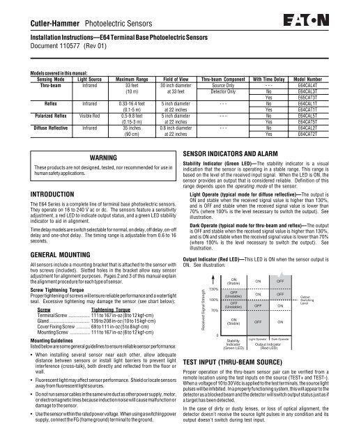
<strong>Cutler</strong>-<strong>Hammer</strong> <strong>Photoelectric</strong> <strong>Sensors</strong><br />
Installation Instructions—E64 Terminal Base <strong>Photoelectric</strong> <strong>Sensors</strong><br />
Document 110577 (Rev 01)<br />
Models covered in this manual:<br />
Sensing Mode Light Source Maximum Range Field of View Thru-beam Component With Time Delay Model Number<br />
Thru-beam Infrared 33 feet 30 inch diameter Source Only - - - E64CAL4T<br />
(10 m) at 33 feet Detector Only No E64CAL3T<br />
Yes E65CAT3T<br />
Reflex Infrared 0.33-16.4 feet 5 inch diameter - - - No E64CAL1T<br />
(0.1-5 m) at 22 inches Yes E64CAT1T<br />
Polarized Reflex Visible Red 0.5-9.8 feet 5 inch diameter - - - No E64CAL5T<br />
(0.15-3 m) at 22 inches Yes E64CAT5T<br />
Diffuse Reflective Infrared 35 inches 0.8 inch diameter - - - No E64CAL2T<br />
(90 cm) at 22 inches Yes E64CAT2T<br />
WARNING<br />
These products are not designed, tested, nor recommended for use in<br />
human safety applications.<br />
INTRODUCTION<br />
The E64 Series is a complete line of terminal base photoelectric sensors.<br />
They operate on 16 to 240 V ac or dc. The sensors feature a sensitivity<br />
adjustment, a red LED to indicate output status, and a green LED stability<br />
indicator to aid in alignment.<br />
Time delay models are switch selectable for normal, on delay, off delay, on-off<br />
delay and one-shot delay. The timing range is adjustable from 0.6 to 16<br />
seconds.<br />
GENERAL MOUNTING<br />
All sensors include a mounting bracket that is attached to the sensor with<br />
two screws (included). Slotted holes in the bracket allow easy sensor<br />
adjustment for alignment purposes. Pages 2 and 3 of this manual explain<br />
the alignment procedure for each type of sensor.<br />
Screw Tightening Torque<br />
Proper tightening of screws will ensure reliable performance and a watertight<br />
seal. Excessive tightening may damage the sensor (see chart below):<br />
Screw Tightening Torque<br />
Terminal Screw ................. 111 to 167 in-oz (8 to 12 kgf-cm)<br />
Gland ................................ 139 to 208 in-oz (10 to 15 kgf-cm)<br />
Cover Fixing Screw ........... 69 to 111 in-oz (5 to 8 kgf-cm)<br />
Mounting Screw ................ 111 to 167 in-oz (8 to 12 kgf-cm)<br />
Mounting Guidelines<br />
listed below are some general guidelines to ensure reliable sensor performance:<br />
• When installing several sensor near each other, allow adequate<br />
distance between sensors or install light barriers to prevent light<br />
interference (cross-talk), both directly and reflected from the floor or<br />
wall.<br />
• Fluorescent light may affect sensor performance. Shield or locate sensors<br />
away from fluorescent light sources.<br />
• Do not run sensor cables in the same wire duct as other power supply, motor,<br />
or electromagnetic lines because induction noise will cause malfunction or<br />
damage to the sensor.<br />
• Use the sensor within the rated power voltage. When using a switching power<br />
supply, connect the FG (frame ground) terminal to the ground.<br />
SENSOR INDICATORS AND ALARM<br />
Stability Indicator (Green LED)—The stability indicator is a visual<br />
indication that the sensor is operating in a stable range. This range is<br />
based on the level of the received input signal. When the LED is ON, the<br />
sensor provides an output that is considered reliable. Definition of this<br />
range depends upon the operating mode of the sensor:<br />
Light Operate (typical mode for diffuse reflective)—The output is<br />
ON and stable when the received signal value is higher than 130%,<br />
and is OFF and stable when the received signal value is lower than<br />
70% (where 100% is the level necessary to switch the output). See<br />
illustration.<br />
Dark Operate (typical mode for thru-beam and reflex)—The output<br />
is OFF and stable when the received signal value is higher than 130%,<br />
and is ON and stable when the received signal value is lower than 70%<br />
(where 100% is the level necessary to switch the output). See<br />
illustration.<br />
Output Indicator (Red LED)—This LED is ON when the sensor output is<br />
ON. See illustration.<br />
Received Signal Strength<br />
130%<br />
100%<br />
70%<br />
0<br />
ON<br />
(Stable)<br />
OFF<br />
(Unstable)<br />
OFF<br />
(Unstable)<br />
ON<br />
(Stable)<br />
Stability<br />
Indicator<br />
(Green LED)<br />
ON<br />
ON<br />
OFF<br />
OFF<br />
Output Indicator<br />
(Red LED)<br />
TEST INPUT (THRU-BEAM SOURCE)<br />
Proper operation of the thru-beam sensor pair can be verified from a<br />
remote location using the test inputs on the source (TEST+ and TEST-).<br />
When a voltage of 10 to 30 Vdc is applied to the test terminals, the source light<br />
pulses will be inhibited. In a properly functioning system, this will appear to the<br />
detector as a blocked beam and the detector will switch output status just as if<br />
a target has been detected.<br />
In the case of dirty or dusty lenses, or loss of optical alignment, the<br />
detector doesn't receive the source light pulses in any condition and its<br />
output doesn't switch during test input.<br />
OFF<br />
OFF<br />
ON<br />
ON<br />
Light Operate Dark Operate<br />
Output<br />
Switching<br />
Level
LOCATION OF CONTROLS AND INDICATORS<br />
The illustrations below show the location of controls and indicators for the<br />
standard and time delay sensor models (shown with cover removed).<br />
STANDARD SENSOR<br />
Output Indicator (Red)<br />
Stability Indicator (Green)<br />
Sensitivity Adjustment<br />
1 3<br />
Power Terminals<br />
Output Terminals<br />
2 4<br />
SENSOR WITH TIME DELAY<br />
Output Indicator (Red)<br />
Stability Indicator (Green)<br />
Sensitivity Adjustment<br />
REFLEX SENSORS<br />
Light/Dark Switch<br />
Timing Function Switch<br />
Time Delay Control<br />
1 3<br />
Power Terminals<br />
Output Terminals<br />
2 4<br />
A reflex sensor has both a light source and detector in the same unit. The source<br />
sends a beam of light to a retroreflector which returns it back to the detector. A<br />
break in the light beam causes the sensor to change output state.<br />
Polarized models are used to reliably detect shiny targets that may reflect<br />
the light beam back to the sensor instead of interrupting the beam. The<br />
polarizing filter conditions the beam so that light reflected off the<br />
retroreflector is detected, but light reflected by the target is not.<br />
USING RETROREFLECTIVE TAPE<br />
Retroreflective tapes can have vastly different properties than cornercube<br />
reflectors. Polarized reflex sensors will not function with some<br />
types of tape. Also, signal strength can drop dramatically as the distance<br />
between tape and sensor is reduced. If you are using a polarized<br />
sensor, or intend to mount the tape closer than 12 inches from the<br />
sensor, we recommend that you test your particular tape prior to<br />
installation.<br />
REFLEX SET-UP<br />
Locate the sensor and retroreflector on opposite sides of the target.<br />
Ensure that the area of the target to be detected will block the entire<br />
beam.<br />
With power applied to the sensor, aim the unit directly at the center of<br />
the retroreflector. Move the sensor back and forth in one plane to find<br />
the extreme positions where the red output LED goes “off” (for light-operate<br />
mode, or “on” for dark-operate mode). Position the sensor midway between the<br />
two extremes. Repeat this procedure for the other plane. The green stability<br />
LED should now be ON with no target in the beam. If it is not, repeat the<br />
alignment procedure. If the green LED is still not ON, the sensor and<br />
TIME DELAY OPERATION (FOR TIME DELAY MODELS)<br />
Timing functions and light/dark operate modes are set using the Timing<br />
Function Switch (located on time delay models only—see “Location of<br />
Controls and Indicators” at left). To set the timing function:<br />
1. Refer to the chart below to determine the switch position for the<br />
desired timing mode. Be sure to choose light or dark operate.<br />
2. Set the Timing Function Switch on the sensor to the proper position.<br />
3. Adjust the time-delay control to the desired delay interval from 0.6 to<br />
16 seconds.<br />
TIMING FUNCTION SWITCH ADJUSTMENTS<br />
Operating Mode<br />
Light Operate<br />
Dark Operate<br />
Normal<br />
One<br />
Shot<br />
ON/OFF<br />
Delay<br />
ON<br />
Delay<br />
OFF<br />
Delay<br />
Normal<br />
One<br />
Shot<br />
ON/OFF<br />
Delay<br />
ON<br />
Delay<br />
OFF<br />
Delay<br />
Switch<br />
Position<br />
7<br />
6<br />
5<br />
4<br />
3<br />
8<br />
9<br />
0<br />
1<br />
2<br />
Light recieved<br />
Light not rec'd.<br />
Output ON<br />
Output OFF<br />
Output ON<br />
Output OFF<br />
Output ON<br />
Output OFF<br />
Output ON<br />
Output OFF<br />
Output ON<br />
Output OFF<br />
Output ON<br />
Output OFF<br />
Output ON<br />
Output OFF<br />
Output ON<br />
Output OFF<br />
Output ON<br />
Output OFF<br />
Output ON<br />
Output OFF<br />
retroreflector may be spaced too far apart (check the maximum sensing<br />
range on the first page of this manual).<br />
After alignment, tighten all mounting screws.<br />
If the sensor has a visible red light source, you can also look at the<br />
retroreflector with your eye as close to the sensor as possible and align the<br />
sensor until reflected light is brightest.<br />
Stretch wrap material over a shiny surface may reflect enough light to false<br />
trigger a polarized reflex sensor. In this case, reduce the gain slightly or tilt the<br />
alignment axis of the sensor relative to the shiny surface.<br />
Center the retroreflector<br />
in the beam. The output<br />
indicator LED will change<br />
state if the retroreflector<br />
moves out of range.<br />
Polarized models “see”<br />
only light rotated 90°.<br />
Polarized light is<br />
rotated 90° by the<br />
retroreflector.<br />
Working<br />
Range<br />
Effective<br />
Beam
DIFFUSE REFLECTIVE SENSORS<br />
A diffuse reflective sensor operates by shining a beam of light out<br />
through the lens. When an object comes within the sensor’s view, it<br />
reflects part of this beam of light back to the sensor causing the sensor<br />
to detect the object. The maximum range at which a given object can be<br />
detected depends on how well its surface reflects light—the less light it<br />
reflects back, the shorter the range. The ability of a surface to reflect light<br />
depends primarily upon its material of construction, color, and texture.<br />
DIFFUSE REFLECTIVE SET-UP<br />
Select a mounting location with a clear view of the object to be detected.<br />
Avoid direct reflection from a highly reflective background (or darken the<br />
background). Mount the sensor so that it points at the most suitable part<br />
of the target object.<br />
Be sure your power supply is off, then connect the sensor to the control<br />
circuit and power lines. Turn the power supply on and place a sample<br />
object in the beam. Slowly turn the gain adjustment clockwise until the red<br />
output LED lights (in light-operate mode). Note the position and remove the<br />
sample object. Now continue turning the sensitivity setting clockwise to find the<br />
position where the LED lights from the background reflection. Reset the<br />
sensitivity midway between the two positions. Tighten all mounting screws.<br />
NOTE: If background reflections are low, it will be possible to achieve a<br />
maximum gain setting without the LED lighting; in that case, set the gain<br />
midway between the first setting and maximum (this will prevent a<br />
hysteresis latch-up after sensing an object).<br />
THRU-BEAM SENSORS<br />
Thru-beam sensors consist of a source and detector positioned on<br />
opposite sides of a detection zone. The source emits infrared light, which<br />
is received by the detector. The detector output switches when this beam<br />
of light is either blocked (when set for dark operation), or un-blocked<br />
(light operation).<br />
THRU-BEAM SET-UP<br />
Aim the source and detector units directly at each other from opposite<br />
sides of the target. (The detector should be on the dirtier side since the<br />
light scattering effect of dirt collecting on the lens is less significant if it<br />
takes place at the detector.) Ensure that the area of the target to be<br />
detected will block the entire beam.<br />
Set the detector to maximum sensitivity. Apply power to both the source and<br />
detector. The red output LED on the detector should be OFF (in dark operate<br />
mode) or ON (in light operate mode). If this is not the case, move the source<br />
and detector so that they are pointed directly at each other until this happens.<br />
Fine tune the alignment by moving the detector back and forth in the horizontal<br />
plane to find the extreme positions where the red output LED changes state (i.e.<br />
goes ON in dark operate mode, or OFF in light operate mode). Position the<br />
sensor midway between the two extremes. Repeat this procedure for the<br />
vertical plane.<br />
Now move the source back and forth in the horizontal plane to find the extreme<br />
positions where the red output LED on the detector changes state. Position the<br />
sensor midway between the two extremes. Repeat this procedure for the<br />
vertical plane.<br />
The green stability LED should now be ON with no target in the beam. If it is<br />
not, repeat the alignment procedure. If the green LED is still not ON, the source<br />
and detector may be spaced too far apart (check the maximum sensing range<br />
on the first page of this manual).<br />
After alignment, tighten all mounting screws.<br />
The detector<br />
“sees” light when<br />
the target surface<br />
enters the<br />
Detection Zone.<br />
Detection<br />
Zone<br />
If the control’s range is greater than<br />
required to detect the target,<br />
background objects may reflect enough<br />
light to trigger the control. Darken the<br />
background or reduce the sensor’s<br />
operating range by turning the<br />
sensitivity control counterclockwise until<br />
the background is no longer detected.<br />
The detector must be placed<br />
within the source beam<br />
pattern (the area containing<br />
all the light rays emitted<br />
by the source).<br />
Source Beam<br />
Pattern<br />
Detector<br />
Working<br />
Range<br />
Working<br />
Range<br />
Effective<br />
Beam Diameter<br />
(Detection Zone)<br />
Target<br />
Object<br />
Required Range<br />
Limit<br />
INSTALLING THE SLIT MASK (OPTIONAL)<br />
Slit masks reduce the size of the<br />
effective beam (see above) for<br />
detection of smaller objects, or<br />
increased accuracy when sensing<br />
the position of a target. The chart<br />
below shows the minimum object<br />
size and the sensing range when<br />
using slit masks.<br />
Source<br />
Detector<br />
Field of View<br />
Target<br />
Object<br />
Background<br />
Object<br />
The source<br />
must be placed<br />
within the<br />
detector field of<br />
view for the<br />
detection<br />
system to<br />
operate.<br />
Only the light source rays that<br />
travel in a straight line to the<br />
receiver (the diameter of the lens)<br />
will be detected. An object must<br />
fully block this beam in order to be<br />
detected.<br />
Slit<br />
Mask<br />
Slit Mask Mounted on: Minimum Object Size Maximum Range<br />
Source OR Detector 0.63 inch (16 mm) Dia. 13.1 feet (4 m)<br />
Source AND Detector 0.12 x 0.39 inch (3 x 10 mm) 6.6 feet (2 m)
<strong>Cutler</strong>-<strong>Hammer</strong> <strong>Photoelectric</strong> <strong>Sensors</strong><br />
SPECIFICATIONS<br />
Input Voltage 16 to 240 V AC or DC; 50/60 Hz<br />
Power Dissipation 3 VA maximum<br />
Output Type SPST relay<br />
Current Switching 1 A @ 250 VAC (resistive load); 2 A @ 30 VDC (resistive load)<br />
Response Time 20 mS maximum<br />
Switching Frequency 2 op./sec maximum<br />
Power-on Delay Output is disabled for 200 mS after power is applied to the<br />
sensor; timing functions start after this 200 mS delay<br />
Light/Dark Operation Switch selectable<br />
Operating Temperature +14° to +140° F (-10° to +60° C)<br />
Storage Temperature -4° to +158° F (-20° to +70° C)<br />
Sensitivity Control Included on all models<br />
Indicator LEDs Red: Output; Green: Stability<br />
Enclosure Ratings IP66; NEMA 1, 3, 4, 12, and 13<br />
Humidity 35% to 85% RH, non-condensing<br />
Housing Material P.B.T.<br />
Lens Material PMMA Methacrylate<br />
Vibration 10 to 55 Hz, amplitude 0.06 inch (1.5 mm) p-p,<br />
2 hours each in axes X, Y, Z<br />
Sunlight Immunity 1,000 foot-candles<br />
Timing Functions Switch selectable for normal, on delay, off delay, on-off delay,<br />
(Time delay models) one-shot delay. 0.6 to 16 Second adjustable timing range<br />
WIRING AND CABLE CONNECTION<br />
Shown in inches (mm)<br />
except where noted<br />
Power Supply<br />
16 to 240<br />
Vac/Vdc<br />
For service or more information call:<br />
1-800-426-9184<br />
DIRECTLINE Application Assistance:<br />
Fax-206-513-5356<br />
Sensor<br />
1 3<br />
2 4<br />
0.31 to 0.39 (8 to 10) Diameter Cable<br />
0.20 (5)<br />
2.35 (60)<br />
Gland Packing<br />
Gland Gland Washer<br />
Output Contact<br />
1 A @ 250 Vac<br />
2 A @ 30 Vdc<br />
Resistive Load<br />
(no connection on<br />
thru-beam source)<br />
Cover<br />
1. Use 0.31 to 0.39 inch (8 to 10 mm) diameter cable to ensure proper<br />
water and dust sealing. Two gland packings are supplied; one for 0.31<br />
to 0.35 inch (8 to 9 mm) diameter cable, and one for 0.35 to 0.39 inch<br />
(9 to 10 mm) diameter cable. Use the proper gland packing and<br />
assemble as shown above. Tighten firmly.<br />
<strong>Cutler</strong>-<strong>Hammer</strong><br />
720 80th Street SW,<br />
Everett, WA 98203-6299<br />
206/353-0900 Fax: 206/513-5302<br />
OPTICAL PERFORMANCE<br />
Dirt in the environment will affect optical performance by reducing the<br />
amount of light the control receives. For best results, sensors should be<br />
used at distances where excess gain is higher than 1.5 (1.5 times the<br />
amount of sensing power required to detect an object under ideal<br />
conditions). Higher excess gain will allow the sensor to overcome higher<br />
levels of contamination on the lens.<br />
1. Thru-beam<br />
2. Reflex<br />
3. Polarized Reflex<br />
Performance to<br />
supplied 2-inch<br />
retroreflector<br />
(E65KR65)<br />
3. Diffuse Reflective<br />
Performance to a<br />
90% reflectance<br />
white card<br />
RANGE (m)<br />
0.03<br />
1000<br />
0.3<br />
3.0 30.5<br />
<strong>Cutler</strong>-<strong>Hammer</strong> <strong>Canada</strong><br />
3228 South Service Rd<br />
Burlington, ON L7N 3H8<br />
800/268-3578 905/333-6442 Fax: 905/333-2724<br />
Specifications subject to change without notice. 110577; Printed in USA (2/96)<br />
EXCESS GAIN<br />
100<br />
APPROXIMATE DIMENSIONS<br />
Shown in inches (mm)<br />
except where noted<br />
Extends:<br />
0.14 (3.5) - Polarized Reflex<br />
0.02 (0.5) - Thru-beam<br />
Thru-beam<br />
lens center<br />
line<br />
1.38<br />
(35)<br />
1.67<br />
(42.5)<br />
M5 Mounting Screws (2 PLS)<br />
2.08 (53)<br />
2.66<br />
(67.5)<br />
10<br />
4<br />
2<br />
3<br />
1<br />
1<br />
0.1 1<br />
10 100<br />
RANGE (feet)<br />
0.39 (10)<br />
0.30 (7.5)<br />
1.02 (26)<br />
LEDs<br />
2.30<br />
(58.5)<br />
0.39 (10)<br />
0.59<br />
(15)<br />
2.16 (55)<br />
0.59<br />
(15)<br />
2.95 (75)<br />
0.83 (21)<br />
2.16 (55)<br />
0.22<br />
(5.5)<br />
ø 0.24 (6)<br />
0.43 (11)<br />
1.08 (27.5)<br />
0.43 (11)<br />
1.38<br />
(35)<br />
0.57<br />
(14.5)<br />
2. Connect wires to lower terminals 2 and 4 first, then upper terminals<br />
1 and 3.<br />
3. Maximum cable length is 328 feet (100 m) when using 22 ga. (0.3<br />
mm2 core) cable or larger wire.


