H-3553 Compact Combo Bubbler System Users Guide ... - WaterLOG
H-3553 Compact Combo Bubbler System Users Guide ... - WaterLOG
H-3553 Compact Combo Bubbler System Users Guide ... - WaterLOG

Create successful ePaper yourself
Turn your PDF publications into a flip-book with our unique Google optimized e-Paper software.
Y S I incorporated<br />
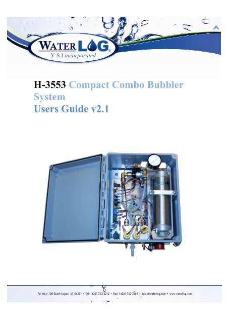
H-<strong>3553</strong> <strong>Compact</strong> <strong>Combo</strong> <strong>Bubbler</strong><br />
<strong>System</strong><br />
<strong>Users</strong> <strong>Guide</strong> v2.1
H-<strong>3553</strong> Table of Contents<br />
Table of Contents T-1<br />
Chapter 1 | Introduction Page<br />
Introduction 1<br />
Key Features 1<br />
Features 1<br />
Chapter 2 | Getting Started Page<br />
Getting Started 3<br />
Unpacking the <strong>System</strong> 3<br />
Product Description 3<br />
Initial Testing 4<br />
Power Up 4<br />
Table 2-1: Main I/O Sensor Interface Cable 4<br />
Using the Display 4<br />
Make Measurement 5<br />
Chapter 3 | Installation Page<br />
Installation 6<br />
Water Depth 6<br />
Table 3-1: H-<strong>3553</strong> Models Pressure Ranges 6<br />
Mounting 6<br />
Desiccator 6<br />
Orifice Line 6<br />
Power Wiring 7<br />
Table 3-2: H-<strong>3553</strong> to XL Series DCP Wiring 7<br />
Chapter 4 | Setup and Operation Page<br />
Setup 8<br />
RS-232 Menu 8<br />
Table 4-1: H-<strong>3553</strong> RS-232 Communication Settings 8<br />
RS-232 Print Out 9<br />
SDI-12 Interface 9<br />
Table 4-2: H-<strong>3553</strong> Standard and Extended SDI-12 Commands 9<br />
Default Setup 10<br />
Table 4-3: H-<strong>3553</strong> Default Setup 10<br />
Reset to Defaults 10<br />
Table 4-4: Reset H-<strong>3553</strong> to Factory Defaults 10<br />
SDI-12 Address 10<br />
Table 4-5: Change the H-<strong>3553</strong> SDI-12 Address 11<br />
Stage Units/Slope 11<br />
Table 4-6: H-<strong>3553</strong> Stage Units and Slopes 11<br />
Table 4-7: Change the H-<strong>3553</strong> Stage Units/Slope 12<br />
Set Current Stage 12<br />
Table 4-8: Set the H-<strong>3553</strong> Current Stage 12<br />
Stage Offset 12<br />
Table 4-9: Change the H-<strong>3553</strong> Stage Offset 13<br />
Page | T-1
Table of Contents H-<strong>3553</strong><br />
Chapter 4 | Setup and Operation (cont’d) Page<br />
Stage Averaging Time 13<br />
Table 4-10: Change the H-<strong>3553</strong> Stage Averaging Time 14<br />
RS-232 Stage Digits 14<br />
Table 4-11: Change the H-<strong>3553</strong> RS-232 Stage Digits 14<br />
Bubble Rate 14<br />
Table 4-12: Bubble Rate vs. Response Time 15<br />
Table 4-13: Change the H-<strong>3553</strong> Bubble Rate 15<br />
Purge 15<br />
Table 4-14: Initiate H-<strong>3553</strong> Purge 16<br />
Purge Pressure 16<br />
Table 4-15: Change the H-<strong>3553</strong> Purge Pressure 17<br />
Purge Sustain 17<br />
Table 4-16: Change the H-<strong>3553</strong> Purge Sustain 17<br />
4-20 Milliamp Output 17<br />
Figure 4-1: Typical H-<strong>3553</strong> 4-20mA Output Setup 18<br />
4-20 Milliamp Min Stage 18<br />
Table 4-17: Change the H-<strong>3553</strong> 4-20 Milliamp Min Stage 18<br />
4-20 Milliamp Max Stage 19<br />
Table 4-18: Change the H-<strong>3553</strong> 4-20 Milliamp Max Stage 19<br />
Modbus Mode Enable 19<br />
Table 4-19: Change the H-<strong>3553</strong> Modbus Mode Enable 20<br />
Auto Mode Enable 20<br />
Table 4-20: Change the H-<strong>3553</strong> Auto Mode Enable 20<br />
Measure Rate (Auto Mode Enabled) 21<br />
Table 4-21: Change the H-<strong>3553</strong> Measure Rate 21<br />
Setup and Operation Conclusion 22<br />
Chapter 5 | Modbus Operation Page<br />
Modbus 23<br />
Communication Setup 23<br />
Table 5-1: H-<strong>3553</strong> RS-485 Modbus Comm Settings 23<br />
Function Codes 23<br />
Table 5-2: H-<strong>3553</strong> Supported Modbus Function Codes 23<br />
Holding Registers 24<br />
Table 5-3: H-<strong>3553</strong> Holding Registers 24<br />
ID String Registers 24<br />
Modbus Address Register 24<br />
Stage Units Select Register 25<br />
Table 5-4: Stage Units Select Register Options 25<br />
Baudrate Select Register 25<br />
Table 5-5: Baudrate Select Register Options 25<br />
Parity Select Register 25<br />
Table 5-6: Parity Select Register Options 25<br />
Bubble Rate Register 26<br />
Purge Pressure Register 26<br />
Page | T-2
H-<strong>3553</strong> Table of Contents<br />
Chapter 5 | Modbus Operation (cont’d) Page<br />
Purge Sustain Register 26<br />
Purge Register 26<br />
Stage Offset Register 26<br />
Stage Slope Register 26<br />
Stage Register 26<br />
Pressure Register 27<br />
Temperature Register 27<br />
Control Battery Register 27<br />
Tank Pressure Register 27<br />
Compressor Battery Register 27<br />
Modbus Command Examples 27<br />
Example #1: Read Holding Register Command 27<br />
Example #2: Write Multiple Registers Command 28<br />
User Agreement/WATERLOG® Warranty W-1<br />
Page | T-3
H-<strong>3553</strong> Chapter 1 | Introduction<br />
| Introduction<br />
The H-<strong>3553</strong> is the “<strong>Compact</strong> <strong>Combo</strong>” bubbler system. The H-<strong>3553</strong> is “<strong>Compact</strong>” because of the smaller<br />
size enclosure compared to its predecessor the H-3551. It is a “<strong>Combo</strong>” because of its built in calibrated<br />
pressure sensor with the bubbler system. The H-<strong>3553</strong> has also been referred to as a self-contained<br />
"smart" gas purge system. The H-<strong>3553</strong> bubbler system produces a precision constant mass flow of gas. It<br />
is used to measure fluid levels in applications such as surface water (streams and lakes, etc.), ground<br />
water and tanks.<br />
The H-<strong>3553</strong> uses a battery operated compressor to maintain pressure in an internal tank. A<br />
microprocessor determines how much pressure is needed in the tank, based on the current head<br />
pressure, to produce a constant bubble rate. Hence, the term "smart". The compressor and tank replace<br />
the dry nitrogen tank used in previous systems.<br />
The H-<strong>3553</strong> uses a sophisticated system of sensors and valves to regulate the bubble rate and purge<br />
pressure. This portion of the H-<strong>3553</strong> replaces the sight feed flow controller and pressure regulator<br />
(Conoflow system) used in previous systems.<br />
The H-<strong>3553</strong> is a standalone system to be used with a Data Collection Platform (DCP). It works best with<br />
the XL series DCP’s, as there are some additional programming options through the XL series DCP. The<br />
XL series DCP’s provide ease of programming in the field with an H-<strong>3553</strong> menu built into the DCP.<br />
The H-<strong>3553</strong> provides a purge feature which temporarily pumps up the tank to a high pressure and opens<br />
a valve to apply high pressure to the orifice line. This feature is designed to remove any sediment that<br />
may have collected in or around the outlet of the orifice line.<br />
| Key Features<br />
• Easy to use standalone RS-232 menu setup<br />
• Built in calibrated pressure sensor<br />
• No external pressure sensor needed<br />
• RS-485 MODBUS Client/Slave device (available in V1.2 or later)<br />
• Auto update mode, measures itself based on user defined rate<br />
• SDI-12 interface, 4 – 20mA output, and RS-232 data output<br />
| Display Features<br />
• Continuous display readout always shows last measured value<br />
• ‘Read’ button causes the H-<strong>3553</strong> to initiate a new measurement<br />
• The adjust knob allows the user to manually set the stage<br />
• The adjust knob allows the user to manually set the sensor SDI-12 address<br />
Page | 1
| Features<br />
• Provides a continuous gas flow<br />
• Battery operated – Low power<br />
• Microprocessor controlled, “smart” gas system<br />
• One-piece manifold eliminates many potential sources of leaks<br />
• Pressure gauge provides a visual indication of the tank pressure<br />
• Hydrophobic intake membrane, protects compressor<br />
• All components are easily accessible for inspection and maintenance<br />
• Compressor does not have a “diaphragm”, it is a piston type<br />
• Provides an internal pressure relief valve<br />
• Compressor is designed and rated for cold temperature operation<br />
• Controlled and monitored as an SDI-12 sensor<br />
Page | 2
H-<strong>3553</strong> Chapter 2 | Getting Started<br />
| Getting Started<br />
Before installing, setup and operation of the H-<strong>3553</strong> <strong>Compact</strong> <strong>Combo</strong> bubbler system in the field read<br />
through this section for a general overview of what you have and how to use it.<br />
| Unpacking the <strong>System</strong><br />
Standard received items:<br />
1. WATERLOG® Series H-<strong>3553</strong> “<strong>Compact</strong> <strong>Combo</strong>” bubbler system<br />
2. Main I/O communications/power cable<br />
3. Mounting Feet Kit<br />
4. This <strong>Users</strong> <strong>Guide</strong><br />
Common optional items:<br />
1. Desiccating Air Dryer<br />
2. Orifice Installation Kit<br />
3. Orifice Line (1000 ft minimum)<br />
4. RS-232 communications cable<br />
5. Replacement Air Dryer Desiccant<br />
Please verify you have received these components and any other optional equipment you may have<br />
ordered.<br />
| Product Description<br />
Atmospheric PSI<br />
vent for sensors<br />
Compressor air intake<br />
Desiccator connection<br />
RS-232 Menu setup port<br />
RS-232 Cable connection<br />
Constant Bubble out<br />
Orifice line connection<br />
1/8 inch FNPT<br />
Compressor power<br />
Connect first!<br />
Enclosure Breather<br />
Power and communications<br />
Main Interface connection<br />
Page | 3
Chapter 2 | Getting Started H-<strong>3553</strong><br />
| Initial Testing<br />
Before installing the H-<strong>3553</strong> in the field, it is a good practice to test the system in the shop or lab. This<br />
will help preparations for a successful field install.<br />
| Power Up<br />
Follow these steps to power up the H-<strong>3553</strong>:<br />
1. Apply +12v to the “Compressor 12VDC” terminal connections<br />
2. Referring to Table 2-1, connect +12 VDC, GND, and SDI-12 data connections of the 7 wire Main<br />
I/O sensor interface pigtail cable to a SDI-12 master device, like an WATERLOG® XL series DCP.<br />
3. Verify the connections Table 2-1, and then connect the Main I/O sensor interface pigtail cable to<br />
the H-<strong>3553</strong> via the 7 pin “Sensor Interface” military grade connector.<br />
4. At power up, the H-<strong>3553</strong> will take an initial atmospheric measurement (listen for a “click” while<br />
the sensors are switched to atmosphere) and then if needed the compressor will turn on to<br />
initialize the tank pressure.<br />
| Using the Display<br />
Page | 4<br />
Table 2-1: Main I/O Sensor Interface Cable<br />
Colors Signal Cable/Bulkhead<br />
Red +12 VDC F<br />
Black GND E<br />
Yellow SDI-12 Data G<br />
Blue 4-20mA + C<br />
Green 4-20mA - D<br />
Orange RS-485 + A<br />
Brown RS-485 - B<br />
B<br />
A<br />
G<br />
C D<br />
F<br />
E<br />
E G B<br />
D<br />
C<br />
Cable Bulkhead<br />
The H-<strong>3553</strong>’s display has a ‘Read’ button that when pressed will cause the unit to initiate a new<br />
measurement and update the display. Measurement requests from an attached SDI-12 data logger will<br />
also cause the display to update.<br />
If the ‘Read’ button is pressed and held until the display starts flashing, the Adjust screw may be turned<br />
to increase or decrease the current stage value. Turning the Adjust screw slowly will change the<br />
hundredths (or thousandths based on the digit setting) digit while turning the screw fast changes the<br />
ones digit. This allows one control to make both fine and course adjustments.<br />
F<br />
A
H-<strong>3553</strong> Chapter 2 | Getting Started<br />
If the ‘Read’ button is held down while the H-<strong>3553</strong> is being powered up, the display will show the<br />
current SDI-12 address. The SDI-12 address may be changed using the Adjust screw. Turning the Adjust<br />
screw will change the address in the range of 0 to 9. When the Read button is released the new SDI-12<br />
address is saved and the display switches to the normal stage readout. To change the SDI-12 address<br />
again, the power must be disconnected and the special power-up sequence repeated.<br />
| Make Measurement<br />
1. Using a SDI-12 master device, like the XL series DCP, send the “0M!” measurement command to<br />
the H-<strong>3553</strong>. Wait about 6 seconds, and then send the “0D0!” data command and verify the data<br />
retrieved with the example below.<br />
Data format: “a + A.AA + B.BBB + CC.C + DD.D + E.EE + FF.F”<br />
a = SDI-12 sensor address<br />
A.AA = Stage (Feet)<br />
B.BBB = Pressure (PSI)<br />
CC.C = Temperature (°C)<br />
DD.D = Sensor Interface Battery (Volts)<br />
E.EE = Tank Pressure (PSI)<br />
F.FF = Compressor Battery (Volts)<br />
Example: “0 + 1.35 + 0.585 + 19.8 + 13.6 + 3.55 + 12.3”<br />
Page | 5
Chapter 3 | Installation H-<strong>3553</strong><br />
| Installation<br />
The WATERLOG® H-<strong>3553</strong> <strong>Compact</strong> <strong>Combo</strong> bubbler system is a bubbler system with a fully integrated<br />
digital pressure transducer specifically designed for water level monitoring. The H-<strong>3553</strong> directly<br />
measures dry gas over a broad temperature range. WARNING! Before proceeding with the installation,<br />
please consider the following site preparation steps to help prevent problems later.<br />
| Water Depth<br />
Table 3-1 shows the maximum pressure to which the H-<strong>3553</strong> is factory calibrated to measure. The<br />
sensor can survive temporary operation up to twice the maximum rated pressure for the model’s range.<br />
However, any measurements made beyond the rated pressure will be inaccurate.<br />
| Mounting<br />
Page | 6<br />
Table 3-1: H-<strong>3553</strong> Models Pressure Ranges<br />
Model Pressure Range Water Depth Range* Accuracy<br />
H<strong>3553</strong>-15 0 to 15 PSI 0 to 34.60 Feet +/- 0.007 Feet<br />
H<strong>3553</strong>-30 0 to 30 PSI 0 to 69.20 Feet +/- 0.014 Feet<br />
*NOTE: Depth calculations are derived from the standard equation that one PSI is generated by<br />
a column of water 2.3067 feet deep.<br />
Consideration should be taken in properly mounting the H-<strong>3553</strong> system. First, attach the included<br />
mounting feet to the H-<strong>3553</strong> enclosure. Mount the H-<strong>3553</strong> in a location where it will not get jarred or<br />
will shift during operation.<br />
When possible mount all equipment with connectors pointing down so that moisture or condensation<br />
that could rest on the connectors does not penetrate the inner components of the equipment. Also,<br />
specifically with the H-<strong>3553</strong>, having it mounted vertically helps prevent moisture from migrating to the<br />
valves. If moisture does migrate, it will migrate first at the bottom of the tank and near the nylon plug.<br />
| Desiccator<br />
Generally, an external desiccator is required to dry the compressor intake air. The desiccator prevents<br />
accumulation of moisture in the tank, manifold and other areas in the system. Connect the output of the<br />
desiccator to the port marked “Inlet”. Desiccators which employ “indicating” silica gel have the<br />
advantage of visually showing the status of the desiccant. As the gel becomes saturated with moisture<br />
the gel changes from blue to pink.<br />
| Orifice Line<br />
The position and installation of the orifice line is vital to a successful and accurate H-<strong>3553</strong> installation.<br />
These are just a few of several things to consider when installing or checking an orifice line installation.<br />
Refer to “AP Note 1005” for more detailed information about orifice line installation.
H-<strong>3553</strong> Chapter 3 | Installation<br />
Be sure the water current or flow is not pushing against the end of the orifice line, as it will cause a<br />
pressure to be placed on the line that is not related to the water depth. Also, be sure the water current<br />
or flow is not pulling or drawing from the end of the orifice line, as this will cause a false lower pressure<br />
on the line not related to the water depth. The line should be installed in an area where the flow of<br />
water will remain relatively calm as compared to the real stage changes. Here are a few Do’s and Do<br />
not’s on mounting the line.<br />
Do:<br />
• Mount the outlet in still water.<br />
• Mount the outlet so the last inch or so is almost horizontal, (slightly downward side exit).<br />
• Try to prevent swells in long runs of orifice line (upward then downward sections).<br />
• Use a muffler in more turbulent waters.<br />
Do not:<br />
• Do not mount the outlet facing up stream, downstream, or upwards.<br />
• Do not allow any portion of the line to be lower than the exit point.<br />
• Do not allow “goose necks” in the orifice line.<br />
• Do not use thin walled tubing, only use USGS approved orifice line.<br />
• Do not mount outlet in the wake of an obstruction, bridge pier, rock, etc.<br />
| Power Wiring<br />
The H-<strong>3553</strong> requires two separate power sources. The first power source to connect is the 2 position<br />
terminal strip labeled “Compressor 12VDC”. This connection is the power source for the compressor and<br />
the control valves. It is recommended using heavier gauge wire (about 18AWG) for this connection and<br />
connecting it directly to the gauge station + 12V battery.<br />
The second power source to connect is the +12V through the circular connector labeled “Sensor<br />
Interface”. This connection is the power source for the circuit board or control module board. It is<br />
recommended to power the control module board via the DCP +12V input instead of using the +12V<br />
switched output. Table 3-2 shows the wiring for connecting the H-<strong>3553</strong> to an XL Series DCP.<br />
Table 3-2: H-<strong>3553</strong> to XL Series DCP Wiring<br />
H-<strong>3553</strong> XL Series DCP<br />
Red (+12V) +12V<br />
Black (Gnd) Gnd (SDI-12)<br />
Yellow (SDI-12) Data (SDI-12)<br />
Note: It is recommended to connect the “Compressor +12VDC” power source first, then the “Sensor<br />
Interface” control module board power second. This is because the H-<strong>3553</strong> makes an initial<br />
measurement at power up and without the compressor and control valves powered the H-<strong>3553</strong> cannot<br />
take an atmospheric measurement to adjust for barometric pressure.<br />
Page | 7
Chapter 4 | Setup and Operation H-<strong>3553</strong><br />
| Setup<br />
There are three ways to setup and operate the H-<strong>3553</strong> <strong>Compact</strong> <strong>Combo</strong> bubbler system, through the RS-<br />
232 menu interface, the SDI-12 interface, and through the XL series DCP menu interface. Setup through<br />
the XL series DCP menu is not discussed in this manual but is discussed in the XL series manual. This<br />
chapter will focus on setup using the RS-232 menu interface and the SDI-12 interface.<br />
| RS-232 Menu<br />
The RS-232 Menu interface is designed to work with a terminal emulator program such as<br />
HyperTerminal, TeraTerm, and ProComm. Table 4-1 shows the settings required to communicate with<br />
the H-<strong>3553</strong> through the RS-232 port.<br />
Page | 8<br />
Table 4-1: H-<strong>3553</strong> RS-232 Communication Settings<br />
Setting Default Setting<br />
Baud Rate 9600<br />
Data Bits 8<br />
Stop Bits 1<br />
Parity None<br />
Duplex Full<br />
Emulation VT-100<br />
Flow Control None<br />
To begin using the RS-232 H-<strong>3553</strong> menu interface, connect the H-<strong>3553</strong> to a computer or other DTE<br />
device with 9 pin serial port using the optional H-<strong>3553</strong> 3 pin RS-232 communications cable. Now, open<br />
the terminal emulator program and press the ‘Enter’ key two times on the computer keyboard to wake<br />
up the H-<strong>3553</strong> and enter the menu. Pressing the ‘Enter’ key once will just force a measurement and not<br />
enter the menu. Pressing the ‘Enter’ key sends a carriage return (CR) and line feed (LF). Initial H-<strong>3553</strong><br />
communication via the RS232 serial port forces a new measurement to be executed which will print out<br />
the message, “Measuring…” When the new measurement is complete the menu below will be displayed<br />
in the terminal emulator window as long as the ‘Enter’ key was press two times.<br />
H-<strong>3553</strong> <strong>Combo</strong> <strong>Bubbler</strong> Setup Menu<br />
A - SDI-12 Address: 0 Serial#: 001000<br />
Version: 1.00<br />
B - <strong>Bubbler</strong> Settings<br />
P - Advanced Options Main Battery: +13.6<br />
Pump Battery: +12.0<br />
Stage Setup:<br />
S - Stage: +0.00 Tank Pressure: +3.24<br />
D - Digits: +2 Line Pressure: +.50<br />
O - Offset: +0.0000 Temperature: +20.5<br />
U - Units: Feet<br />
L - Slope: +2.30670<br />
M - Measure<br />
X - Exit<br />
Enter Option >
H-<strong>3553</strong> Chapter 4 | Setup and Operation<br />
| RS-232 Print Out<br />
The RS-232 port on the H-<strong>3553</strong> is primarily used for setup and operation, but can also be used for<br />
sending the current stage and temperature data. When the H-<strong>3553</strong> makes a new measurement it will<br />
print the following data message out the RS-232 port.<br />
Stage = +1.23<br />
Temp = +12.3<br />
The RS-232 port can also be used to initiate new measurements. This is done by sending any character<br />
to the H-<strong>3553</strong> RS-232 port and the H-<strong>3553</strong> will make a new measurement and print out the above<br />
mentioned data message out the RS-232 port. Note: When the H-<strong>3553</strong> Modbus or Auto mode is enabled<br />
it will enter the RS-232 menu with any character sent to this port.<br />
| SDI-12 Interface<br />
The SDI-12 interface is another way to setup and operate the H-<strong>3553</strong>. The H-<strong>3553</strong> supports all standard<br />
SDI-12 commands and uses some SDI-12 extended (manufacturer specific) commands for setup<br />
operation. SDI-12 standard and extended commands are normally sent from a SDI-12 master device, like<br />
the Waterlog XL series DCP. Table 4-2 is a list of the standard SDI-12 commands and the extended SDI-12<br />
commands for setting up the H-<strong>3553</strong>.<br />
Table 4-2: H-<strong>3553</strong> Standard and Extended SDI-12 Commands<br />
Command Description Command Description<br />
Standard SDI-12 Commands<br />
a! Acknowledge aM2! Initiate Purge<br />
aI! Identify aC! – aC9! Concurrent Measure<br />
aV! Verify aCC! – aCC9! Concurrent Measure w/CRC<br />
aM! – aM1! Measure aD0! – aD9! Data Retrieval<br />
aMC! – MC1! Measure with CRC aAn! Change Address<br />
Extended SDI-12 Commands<br />
aXSDEF! Reset to Defaults aXRPP! Read Purge Pressure<br />
aXWSn.nn! Write Stage Slope aXWPSnn! Write Purge Sustain<br />
aXRS! Read Stage Slope aXRPS! Read Purge Sustain<br />
aXSCSn.nn! Set Current Stage aXWIHn.nn! Write 4-20mA Stage Max<br />
aXWOn.nn! Write Stage Offset aXRIH! Read 4-20mA Stage Max<br />
aXRO! Read Stage Offset aXWILn.nn! Write 4-20mA Stage Min<br />
aXWATnn! Write Averaging Time aXRIL! Read 4-20mA Stage Min<br />
aXRAT! Read Averaging Time aXWMEn! Write Modbus enable<br />
aXWSDn! Write RS-232 Stage Digits aXRMEn! Read Modbus enable<br />
aXRSD! Read RS-232 Stage Digits aXWAEn! Write Auto enable<br />
aXWBRnn! Write Bubble Rate aXRAEn! Read Auto enable<br />
aXRBR! Read Bubble Rate aXWMRnn! Write Measure Rate<br />
aXWPPnn! Write Purge Pressure aXRMR! Read Measure Rate<br />
aXTD! Test Display aXHELP! Display a List of Commands<br />
Page | 9
Chapter 4 | Setup and Operation H-<strong>3553</strong><br />
Note, the ‘a’ character in Table 4-2 represents the current SDI-12 address of the H-<strong>3553</strong> and the ‘n’<br />
characters represent the new value to be written. Each H-<strong>3553</strong> extended SDI-12 command is discussed<br />
in more detail later in the chapter.<br />
| Default Setup<br />
The H-<strong>3553</strong> has many settings that can be change. However, the default setups will normally cover most<br />
applications. Table 4-3 shows the default settings for the H-<strong>3553</strong> <strong>Compact</strong> <strong>Combo</strong> bubbler system.<br />
Page | 10<br />
Table 4-3: H-<strong>3553</strong> Default Setup<br />
Setting Default Setting Setting Range<br />
SDI-12 Address 0 0 - 9 (Standard), A-Z, a-z<br />
Stage Units Feet (Slope = 2.3067) Ft, In, M, mm, Ft Dn, Usr Def<br />
Stage Offset 0.0 N/A<br />
SDI-12 Stage Digits 3 N/A<br />
RS-232 Stage Digits 2 0 – 6<br />
Averaging Time 2 Seconds 1 – 65535 seconds<br />
Bubble Rate 60 bubbles/min 30 – 120 bubbles/min<br />
Purge Pressure 40 PSI (15 PSI Sensor)<br />
50 PSI (30 PSI Sensor)<br />
30 – 90 PSI<br />
Purge Sustain 20 seconds 10 – 240 seconds<br />
4 – 20mA Min Stage 4.0 N/A<br />
4 – 20mA Max Stage 20.0 N/A<br />
| Reset to Defaults<br />
It may be necessary to reset the H-<strong>3553</strong> settings back to factory defaults. Using the RS-232 menu, press<br />
the ‘P’ key to enter the “Advanced Options” menu and then press the ‘D’ key to “Reset Defaults”.<br />
To reset to defaults using the SDI-12 interface, send the “aXSDEF!” SDI-12 extended command. The<br />
response should be “a0041” which means that it will take 4 seconds to reset to defaults. Note in Table<br />
4-4, the ‘a’ is the current address of the H-<strong>3553</strong>.<br />
Table 4-4: Reset H-<strong>3553</strong> to Factory Defaults<br />
H-<strong>3553</strong> <strong>Combo</strong> <strong>Bubbler</strong> Setup Menu SDI-12 Interface<br />
P – Advanced Options Command: aXSDEF!<br />
: Response: a0041<br />
Advanced Options Menu<br />
D – Reset Defaults<br />
Resetting to Defaults . . .
H-<strong>3553</strong> Chapter 4 | Setup and Operation<br />
| SDI-12 Address<br />
The SDI-12 address of a sensor is its identifier on the SDI-12 data bus. The SDI-12 data bus is a one wire<br />
communication between normally one master device and one or more slave devices. The SDI-12<br />
address makes it possible for the master device to communicate with each sensor individually. SDI-12<br />
data collisions will occur when two or more sensors have the same address on the same data bus. The<br />
sensors with the same address will try to respond to the request of the master device at the same time<br />
and the result is garbage data. Therefore, it is important to know the address of the sensor to which<br />
communication is desired and that there are no other sensors with the same address.<br />
The H-<strong>3553</strong> SDI-12 address by default is 0. To change the H-<strong>3553</strong> SDI-12 address using the RS-232 main<br />
menu, press the ‘A’ key and enter in the new “SDI-12 address”.<br />
To change the H-<strong>3553</strong> SDI-12 address using the SDI-12 interface, send the “aAn!” command and the<br />
response should be ‘n’, the new address. Note in Table 4-5, the ‘a’ is the current address of the H-<strong>3553</strong><br />
and the ‘n’ is the desired new SDI-12 address.<br />
| Stage Units/Slope<br />
Table 4-5: Change the H-<strong>3553</strong> SDI-12 Address<br />
H-<strong>3553</strong> <strong>Combo</strong> <strong>Bubbler</strong> Setup Menu SDI-12 Interface<br />
A – SDI-12 Address: a Command: aAn!<br />
Enter New SDI-12 Address [ n ] Response: n<br />
The stage unit of a sensor is the setting that determines the data output units. Different data units are<br />
dependent on the slope/multiplier. The slope is multiplied by the raw data to achieve the desired units.<br />
For example, a pressure sensor raw data output might be in pressure (PSI) units, but the desired units by<br />
the user is feet. Therefore, the slope to convert PSI to Feet units for water depth is 2.0367 rounded.<br />
The H-<strong>3553</strong> has a pressure sensor that measures the pressure required to push a bubble out of the<br />
orifice line, which is the line pressure. The line pressure raw value is returned in pressure (PSI) units.<br />
Normally, water depth in feet or meters is the stage units desired. This then requires the line pressure<br />
value to be changed to a different set of units. Table 4-6 shows typical slopes required to convert<br />
pressure (PSI) units to other different stage units.<br />
Table 4-6: H-<strong>3553</strong> Stage Units and Slopes<br />
Units Slopes (multiplier)<br />
Feet 2.3067<br />
Meters 0.7031<br />
Inches 27.6800<br />
Millimeters 0.0007031<br />
Centimeters 0.007031<br />
Feet down -2.3067<br />
PSI 1.0000<br />
Page | 11
Chapter 4 | Setup and Operation H-<strong>3553</strong><br />
The H-<strong>3553</strong> stage unit default is feet, which is a default slope of 2.0367. To change the stage<br />
units/slope using the RS-232 main menu, press the ‘U’ key and then the up and down arrow keys to<br />
toggle to the desired units, then press the ‘Enter’ key. If the desired stage unit is not listed change the<br />
stage units to user defined, press the ‘L’ key and enter in the desired slope.<br />
To change the H-<strong>3553</strong> stage slope using the SDI-12 interface, send the “aXWSn.nn!” SDI-12 extended<br />
command. The response should be “a0021” which means that it will take 2 seconds to complete the<br />
command and then it will put 1 data value in the buffer. To check the slope and verify it was written<br />
correctly send “aXRS!” and wait the responded time. Then send the “aD0!” command to read back the<br />
new slope. Note Table 4-7, the ‘a’ is the current SDI-12 address of the H-<strong>3553</strong> and the ‘xxxx’/’x.xxx’ is the<br />
current units/slope of the H-<strong>3553</strong> and the ‘nnnn’/’n.nnn’ is the desired new units/slope.<br />
| Set Current Stage<br />
Page | 12<br />
Table 4-7: Change the H-<strong>3553</strong> Stage Units/Slope<br />
H-<strong>3553</strong> <strong>Combo</strong> <strong>Bubbler</strong> Setup Menu SDI-12 Interface<br />
U – Units: xxxx Command: aXWSn.nnn!<br />
Stage Units [ nnnn ] Response: a0021<br />
L – Slope: x.xxx Command: aXRS!<br />
Enter Slope Value [ n.nnn ] Response: a0011<br />
Command: aD0!<br />
Response: a + n.nnn<br />
Set current stage is setting the stage to the actual measured or surveyed value, this could include the<br />
elevation or not. Normally, the current stage value comes from a wire weight reading or a surveyed staff<br />
gauge reading.<br />
Setting the current stage in the H-<strong>3553</strong> forces a new measurement and then compares the result of that<br />
measurement with the desired current stage and then calculates and sets the stage offset. To set the<br />
current stage using the RS-232 main menu, press the ‘S’ key, enter in the current “Stage” and then press<br />
the ‘Enter’ key.<br />
To set current stage using the SDI-12 interface, send the “aXSCSn.nn!” SDI-12 extended command. The<br />
response should be “a0061” which means that it will take 6 seconds to complete the command and then<br />
it will put 1 data value in the buffer. To check if the stage was set correctly, send the “aM!”<br />
measurement command, wait the responded time and then send the “aD0” and verify the stage level<br />
value. Note Table 4-8, the ‘a’ is the current SDI-12 address of the H-<strong>3553</strong> and the ‘x.xxx’ is the current<br />
measured stage of the H-<strong>3553</strong> and the ’n.nnn’ is the desired new current stage.<br />
Table 4-8: Set the H-<strong>3553</strong> Current Stage<br />
H-<strong>3553</strong> <strong>Combo</strong> <strong>Bubbler</strong> Setup Menu SDI-12 Interface<br />
S – Stage: x.xxx Command: aXSCSn.nnn!<br />
Enter Stage Value [ n.nnn ] Response: a0061<br />
Command: aM!<br />
Response: a0066<br />
Command: aD0!<br />
Response: a + n.nnn +…
H-<strong>3553</strong> Chapter 4 | Setup and Operation<br />
Note: The last section of this chapter discusses the “Set Current Stage” section as the most used option.<br />
| Stage Offset<br />
The stage offset is a value that is added to the final stage result after the slope/multiplier has been<br />
applied. The stage offset is normally used to obtain a final stage level relative to some reference point<br />
such as sea level. Writing the stage offset is not needed when using the set current stage option,<br />
because this option calculates and sets the stage offset automatically.<br />
The H-<strong>3553</strong> stage offset default is 0.000. To change the stage “Offset” using the RS-232 main menu,<br />
press the ‘O’ key, enter the new stage offset and then press the ‘Enter’ key.<br />
To change the H-<strong>3553</strong> stage offset using the SDI-12 interface, send the “aXWOn.nn!” SDI-12 extended<br />
command. The response should be “a0021” which means that it will take 2 seconds to complete the<br />
command and then it will put 1 data value in the buffer. To check the offset and verify it was written<br />
correctly send “aXRO!” and wait the responded time. Then send the “aD0!” command to read back the<br />
new offset. Note Table 4-9, the ‘a’ is the current SDI-12 address of the H-<strong>3553</strong> and the ‘x.xxx’ is the<br />
current offset of the H-<strong>3553</strong> and the ’n.nnn’ is the desired new stage offset.<br />
| Stage Averaging Time<br />
Table 4-9: Change the H-<strong>3553</strong> Stage Offset<br />
H-<strong>3553</strong> <strong>Combo</strong> <strong>Bubbler</strong> Setup Menu SDI-12 Interface<br />
O – Offset: x.xxx Command: aXWOn.nnn!<br />
Enter Offset Value [ n.nnn ] Response: a0021<br />
Command: aXRO!<br />
Response: a0011<br />
Command: aD0!<br />
Response: a + n.nnn<br />
The stage averaging time is the setting that determines how long in seconds the H-<strong>3553</strong> will average the<br />
measurements before returning the final stage value. It is important to sample multiple times to ensure<br />
accuracy of a reading, especially if the water is rough. The stage averaging time may need to be<br />
adjusted to help smooth out choppy data due to wave action.<br />
The H-<strong>3553</strong> stage averaging time default is 2 seconds, which is equal to about 10 samples. The stage<br />
averaging time range is 1 to 65535 seconds. To change the averaging time using the RS-232 main menu,<br />
press the ‘P’ key to enter the “Advanced Options” menu, then press the ‘T’ key, enter in the new<br />
“Averaging Time” and press the ‘Enter’ key.<br />
To set the stage averaging time using the SDI-12 interface, send the “aXWATnn!” SDI-12 extended<br />
command. The response should be “a0021” which means that it will take 2 seconds to complete the<br />
command and then it will put 1 data value in the buffer. To check if the averaging time was set correctly,<br />
send “aXRAT!” command, wait the responded time and then send the “aD0” and verify the averaging<br />
time value. Note Table 4-10, the ‘a’ is the current SDI-12 address of the H-<strong>3553</strong> and the ‘x’ is the current<br />
averaging time of the H-<strong>3553</strong> and the ‘n’ is the desired stage averaging time.<br />
Page | 13
Chapter 4 | Setup and Operation H-<strong>3553</strong><br />
Note: This averaging time does not take into account the time it takes to make an atmospheric reading.<br />
Therefore, always and about 4 more seconds to the averaging time to calculate how long the full<br />
measurement cycle can take.<br />
| RS-232 Stage Digits<br />
Page | 14<br />
Table 4-10: Change the H-<strong>3553</strong> Stage Averaging Time<br />
H-<strong>3553</strong> <strong>Combo</strong> <strong>Bubbler</strong> Setup Menu SDI-12 Interface<br />
P – Advanced Options Command: aXWATn!<br />
: Response: a0021<br />
Advanced Options Menu Command: aXRAT!<br />
T – Averaging Time: x Response: a0011<br />
Averaging Time [ nnn ] Command: aD0!<br />
Response: a + nnn<br />
The RS-232 stage digits are the setting that determines how many digits are displayed to the right of the<br />
decimal place for the measured value when printed out the RS-232 port. Normally, two digits to the<br />
right of the decimal place is the standard when measuring stage in feet.<br />
The H-<strong>3553</strong> RS-232 stage digits default is 2. To change the “Stage Digits” using the RS-232 main menu,<br />
press the ‘D’ key, enter in the new stage digits and then press the ‘Enter’ key.<br />
To change the H-<strong>3553</strong> RS-232 stage digits using the SDI-12 interface, send the “aXWSDn!” SDI-12<br />
extended command. The response should be “a0021” which means that it will take 2 seconds to<br />
complete the command and then it will put 1 data value in the buffer. To check the stage digits and<br />
verify it was written correctly send “aXRSD!” and wait the responded time. Then send the “aD0!”<br />
command to read back the new stage digits. Note Table 4-11, the ‘a’ is the current SDI-12 address of the<br />
H-<strong>3553</strong> and the ‘x’ is the current stage digits of the H-<strong>3553</strong> and the ‘n’ is the desired new stage digits.<br />
| Bubble Rate<br />
Table 4-11: Change the H-<strong>3553</strong> RS-232 Stage Digits<br />
H-<strong>3553</strong> <strong>Combo</strong> <strong>Bubbler</strong> Setup Menu SDI-12 Interface<br />
D – Digits: x Command: aXWSDn!<br />
Stage Digits [ n ] Response: a0021<br />
Command: aXRSD!<br />
Response: a0011<br />
Command: aD0!<br />
Response: a + n<br />
The bubble rate is the average number of bubbles flowing from the end of the orifice line per minute.<br />
The standard orifice line tubing that we recommend and calibrate the bubble rate has 1/8 inch inner<br />
diameter (I.D.). If a different size orifice I.D. is used the bubble rate will not be correct.
H-<strong>3553</strong> Chapter 4 | Setup and Operation<br />
The bubble rate is a determining factor in the response time of the H-<strong>3553</strong> tracking a rise in stage. Table<br />
4-12 shows the approximate time needed to respond and track a one foot rise in stage with different<br />
bubble rates. Note this is at a depth of one foot, at greater depths the time will increase slightly.<br />
Table 4-12: Bubble Rate vs. Response Time<br />
Bubble Rate Response for 1 Ft Rise<br />
30 bubbles/min 25 seconds<br />
60 bubbles/min 20 seconds<br />
120 bubbles/min 15 seconds<br />
Another reason for changing the bubble rate may be to reduce noise in the data. Some sites have<br />
turbulent water conditions creating water level data that looks jittery. The bubble rate may be changed,<br />
up or down, to find optimal results to reduce this noise. Normally, it is a combination of changing the<br />
bubble rate and the mean count/samples to produce the best results. The default values normally work<br />
best in the majority of the applications and provide desirable results in a timely manner.<br />
The H-<strong>3553</strong> bubble rate default is set to 60 bubbles/min. The bubble rate range is 30 to 120<br />
bubbles/min. To change the bubble rate using the RS-232 main menu, press the ‘B’ key to enter the<br />
“<strong>Bubbler</strong> Settings” menu, then press the ‘B’ key, enter in the new desired “Bubble Rate” and press the<br />
‘Enter’ key.<br />
To change the H-<strong>3553</strong> bubble rate using the SDI-12 interface, send the “aXWBRnn!” SDI-12 extended<br />
command. The response should be “a0061” which means that it could take 6 seconds to complete the<br />
command and then it will put 1 data value in the buffer. To check the bubble rate and verify it was<br />
written correctly send “aXRBR!” command and wait the responded time. Then send the “aD0!”<br />
command to read back the new bubble rate. Note Table 4-13, the ‘a’ is the current SDI-12 address of the<br />
H-<strong>3553</strong> and the ‘xx’ is the current bubble rate of the H-<strong>3553</strong> and the ‘nn’ is the desired bubble rate.<br />
| Purge<br />
Table 4-13: Change the H-<strong>3553</strong> Bubble Rate<br />
H-<strong>3553</strong> <strong>Combo</strong> <strong>Bubbler</strong> Setup Menu SDI-12 Interface<br />
B – <strong>Bubbler</strong> Settings Command: aXWBRnn!<br />
: Response: a0061<br />
<strong>Bubbler</strong> Settings Menu Command: aXRBR!<br />
B – <strong>Bubbler</strong> Rate: xx Response: a0021<br />
Enter Bubble Rate (30-120) [ nn ] Command: aD0!<br />
Response: a + nn<br />
The H-<strong>3553</strong> <strong>Compact</strong> <strong>Combo</strong> bubbler system has an option built in called purge, the purpose of the<br />
purge is to clear out any debris or silt from the end of the orifice line that could cause false pressure<br />
readings.<br />
When a purge is initiated the H-<strong>3553</strong> makes a new measurement on the line and tank sensor and saves<br />
the values away just in case data is requested during the purge. The compressor is then turned on and<br />
begins compressing air into the tank until the tank pressure is equal to or greater than the purge<br />
Page | 15
Chapter 4 | Setup and Operation H-<strong>3553</strong><br />
pressure value. Then the purge valve is opened which then releases the tank pressure into the orifice<br />
line. The compressor will continue to run until the purge sustain timer has elapsed. Then the H-<strong>3553</strong><br />
monitors the tank pressure which is still open to the orifice and waits for it to stabilize. Finally, the purge<br />
valve closes and the H-<strong>3553</strong> purge process is complete. Shortly following the purge sequence the H-<br />
<strong>3553</strong> will need to recharge the tank pressure to maintain the bubble rate and continue normal<br />
operation.<br />
There are three ways to initiate a purge, push the “PURGE” button, the RS-232 menu, and the SDI-12<br />
interface. To initiate a purge with the button, open the H-<strong>3553</strong> enclosure lid and locate the a white push<br />
button on the circuit board labeled “PURGE”, press and hold for about 2 seconds.<br />
To initiate a purge using the RS-232 main menu, press ‘B’ key to enter the “<strong>Bubbler</strong> Settings” menu and<br />
then press the ‘M’ key for “Manual Purge”. To initiate a purge using the SDI-12 interface, send the<br />
“aXP!” command or the “aM2!” command. Note Table 4-14, the ‘a’ is the current SDI-12 address of the<br />
H-<strong>3553</strong>. The ‘ttt’ is the time it will take to complete the purge, which is dependent on other factors like<br />
averaging time and purge sustain. The ‘dd.d’ is the compressor battery voltage measured immediately<br />
following the completed purge sequence.<br />
| Purge Pressure<br />
Page | 16<br />
Table 4-14: Initiate H-<strong>3553</strong> Purge<br />
H-<strong>3553</strong> <strong>Combo</strong> <strong>Bubbler</strong> Setup Menu SDI-12 Interface<br />
B – <strong>Bubbler</strong> Settings Command: aXP! / aM2!<br />
: Response: attt1<br />
<strong>Bubbler</strong> Settings Menu Command: aD0!<br />
M – Manual Purge Response: a + dd.d<br />
Initiating Purge . . .<br />
The purge pressure is the pressure that is used to purge the orifice line. This is normally done to clear<br />
the end of the orifice line of debris and or sediment buildup. “False high stage” readings can be caused<br />
by debris or sediment buildup at the end of the orifice line. This is because it will cause more restriction<br />
when trying to push a bubble out which is like the stage is rising. This may cause a saw tooth profile in<br />
your data. As pressure keeps building up until the bubble pushes out past the debris or sediment<br />
relieving the pressure in the line. Then the pressure starts building up again causing saw tooth data.<br />
The H-<strong>3553</strong> purge pressure default is set to 40 PSI (15 PSI sensor) or 50 PSI (30 PSI sensor). The<br />
programmable purge pressure range is 30 to 90 PSI. To change the “Purge Pressure” using the RS-232<br />
main menu, press the ‘B’ key to enter the “<strong>Bubbler</strong> Settings” menu and then press the ‘P’ key, then<br />
enter in the desired purge pressure and press the ‘Enter’ key.<br />
To change the H-<strong>3553</strong> purge pressure using the SDI-12 interface, send the “aXWPPnn!” SDI-12 extended<br />
command. The response should be “a0061”, which means that it could take 6 seconds to complete the<br />
command and then it will put 1 data value in the buffer. To check the new purge pressure, send<br />
“aXRPP!” command and wait the responded time. Send the “aD0!” command to read back the new<br />
written purge pressure. Note Table 4-15, the ‘a’ is the current SDI-12 address of the H-<strong>3553</strong> and the ‘xx’<br />
is the current purge pressure of the H-<strong>3553</strong> and the ‘nn’ is the desired purge pressure.
H-<strong>3553</strong> Chapter 4 | Setup and Operation<br />
| Purge Sustain<br />
Table 4-15: Change the H-<strong>3553</strong> Purge Pressure<br />
H-<strong>3553</strong> <strong>Combo</strong> <strong>Bubbler</strong> Setup Menu SDI-12 Interface<br />
B – <strong>Bubbler</strong> Settings Command: aXWPPnn!<br />
: Response: a0061<br />
<strong>Bubbler</strong> Settings Menu Command: aXRPP!<br />
P – Purge Pressure: xx Response: a0021<br />
Enter Purge Pressure (15-90) [ nn ] Command: aD0!<br />
Response: a + nn<br />
The purge sustain is part of the purge sequence discussed earlier, it is the time in seconds that the<br />
compressor will keep running after the tank pressure is released into the orifice line. The purge sustain<br />
helps clear out heavier sediment buildup and or bigger blocks at the end of the orifice because of<br />
sustaining a higher pressure.<br />
The H-<strong>3553</strong> purge sustain default time is set to 20 seconds. The programmable purge sustain range is 10<br />
to 240 seconds. To change the purge sustain time using the RS-232 main menu, press the ‘B’ key to<br />
enter the “<strong>Bubbler</strong> Settings” menu and then press the ‘S’ key, enter in the desired “Purge Sustain” time<br />
and then press the ‘Enter’ key.<br />
To change the H-<strong>3553</strong> purge sustain using the SDI-12 interface; send the “aXWPSnn!” SDI-12 extended<br />
command. The response should be “a0061”, which means that it could take 6 seconds to complete the<br />
command and then it will put 1 data value in the buffer. To check the new purge sustain time, send<br />
“aXRPS!” command and wait the responded time. Send the “aD0!” command to read back the new<br />
written purge sustain time. Note Table 4-16, the ‘a’ is the current SDI-12 address of the H-<strong>3553</strong> and the<br />
‘xx’ is the current purge sustain time of the H-<strong>3553</strong> and the ‘nn’ is the desired purge sustain time.<br />
| 4-20 Milliamp Output<br />
Table 4-16: Change the H-<strong>3553</strong> Purge Sustain<br />
H-<strong>3553</strong> <strong>Combo</strong> <strong>Bubbler</strong> Setup Menu SDI-12 Interface<br />
B – <strong>Bubbler</strong> Settings Command: aXWPSnn!<br />
: Response: a0061<br />
<strong>Bubbler</strong> Settings Menu Command: aXRPS!<br />
S – Purge Sustain: xx Response: a0021<br />
Enter Purge Sustain (10-240) [ nn ] Command: aD0!<br />
Response: a + nn<br />
The H-<strong>3553</strong> has the ability to output the stage value as a 4-20 milliamp signal. The 4-20 milliamp output<br />
is most commonly used in industrial applications with PLC’s or SCADA systems. The H-<strong>3553</strong> controls the<br />
loop current but does not power the loop. Therefore, the loop must be externally powered. Figure 4-1<br />
below shows a basic wiring diagram for a 4-20 milliamp output loop with the H-<strong>3553</strong>. The battery in the<br />
loop should be a +24VDC power source.<br />
Page | 17
Chapter 4 | Setup and Operation H-<strong>3553</strong><br />
Page | 18<br />
Figure 4-1: Typical H-<strong>3553</strong> 4-20mA Output Setup<br />
4-20mA<br />
Input<br />
Device<br />
+<br />
-<br />
Battery<br />
Blue (Out +)<br />
Green (Out -)<br />
H-<strong>3553</strong><br />
The H-<strong>3553</strong> scales the current measured stage reading for the 4-20 milliamp output based on the 4-20<br />
milliamp min and max stage values.<br />
| 4-20 Milliamp Min Stage<br />
The 4-20 milliamp min stage value should be the lowest the stage gets at the installed site. When the<br />
stage equals this value or lower the 4-20 milliamp output will be 4.0 milliamps, the min.<br />
The H-<strong>3553</strong> 4-20 milliamp min stage default value is set to 4. There is no limit to this value, but keep in<br />
mind that the smaller the overall range of the 4-20 stage scalar, which is the min to the max stage, the<br />
more accurate the 4-20 milliamp output will be. To change the 4-20 milliamp min stage using the RS-<br />
232 main menu, press the ‘P’ key to enter the “Advanced Options” menu and then press the ‘F’ key to<br />
enter the “4-20mA Output Setup” menu. Then press the ‘N’ key in this menu and enter in the new “Min<br />
Stage” value and press the ‘Enter’ key.<br />
To change the H-<strong>3553</strong> 4-20 milliamp min stage using the SDI-12 interface, send the “aXWILn.nn!” SDI-12<br />
extended command. The response should be “a0021”, which means that it could take 2 seconds to<br />
complete the command and then it will put 1 data value in the buffer. To check the new 4-20 milliamp<br />
min stage, send “aXRIL!” command and wait the responded time. Then send the “aD0!” command to<br />
read back the new written 4-20 milliamp min stage. Note Table 4-17, the ‘a’ is the current SDI-12<br />
address of the H-<strong>3553</strong> and the ‘x.xx’ is the current 4-20 milliamp min stage and the ‘n.nn’ is the desired<br />
4-20 milliamp min stage.<br />
Table 4-17: Change the H-<strong>3553</strong> 4-20 milliamp Min Stage<br />
H-<strong>3553</strong> <strong>Combo</strong> <strong>Bubbler</strong> Setup Menu SDI-12 Interface<br />
P – Advanced Options Command: aXWILn.nn!<br />
: Response: a0021<br />
Advanced Options Menu Command: aXRIL!<br />
F – 4-20mA Output Response: a0011<br />
: Command: aD0!<br />
4-20mA Output Setup Menu Response: a + n.nn<br />
N – Min Stage: x.xx<br />
Enter 4-20mA Min Stage [ n.nn ]
H-<strong>3553</strong> Chapter 4 | Setup and Operation<br />
| 4-20 Milliamp Max Stage<br />
The 4-20 milliamp max stage value should be the highest the stage gets at the installed site. When the<br />
stage equals this value or greater the 4-20 milliamp output will be 20.0 milliamps, the max.<br />
The H-<strong>3553</strong> 4-20 milliamp max stage default value is set to 20. There is no limit to this value, but keep in<br />
mind that the smaller the overall range of the 4-20 stage scalar, which is the min to the max stage, the<br />
more accurate the 4-20 milliamp output will be. To change the 4-20 milliamp max stage using the RS-<br />
232 main menu, press the ‘P’ key to enter the “Advanced Options” menu and then press the ‘F’ key to<br />
enter the “4-20mA Output Setup” menu. Then press the ‘X’ key in this menu, enter in the new “Max<br />
Stage” value and press the ‘Enter’ key.<br />
To change the H-<strong>3553</strong> 4-20 milliamp max stage using the SDI-12 interface, send the “aXWIHn.nn!” SDI-<br />
12 extended command. The response should be “a0021”, which means that it could take 2 seconds to<br />
complete the command and then it will put 1 data value in the buffer. To check the new 4-20 milliamp<br />
max stage, send “aXRIH!” command and wait the responded time. Then send the “aD0!” command to<br />
read back the new written 4-20 milliamp max stage. Note Table 4-18, the ‘a’ is the current SDI-12<br />
address of the H-<strong>3553</strong> and the ‘x.xx’ is the current 4-20 milliamp max stage and the ‘n.nn’ is the desired<br />
4-20 milliamp max stage.<br />
| Modbus Mode Enable<br />
Table 4-18: Change the H-<strong>3553</strong> 4-20 milliamp Max Stage<br />
H-<strong>3553</strong> <strong>Combo</strong> <strong>Bubbler</strong> Setup Menu SDI-12 Interface<br />
P – Advanced Options Command: aXWIHn.nn!<br />
: Response: a0021<br />
Advanced Options Menu Command: aXRIH!<br />
F – 4-20mA Output Response: a0011<br />
: Command: aD0!<br />
4-20mA Output Setup Menu Response: a + n.nn<br />
X – Max Stage: x.xx<br />
Enter 4-20mA Max Stage [ n.nn ]<br />
The Modbus mode enable is the setting that determines whether the H-<strong>3553</strong> will communicate with a<br />
Modbus master device. Modbus is an industry standard serial digital interface for interconnecting<br />
Programmable Logic Controllers (PLCs), intelligent sensors and other devices. The H-<strong>3553</strong> can be used as<br />
a Modbus slave and has a serial RS-485 port for connecting to a Modbus compatible host device. See the<br />
“Chapter 5 Modbus Operation” for more information on Modbus settings Modbus register definitions.<br />
Note: this mode requires more power because it does not go to sleep, the normal operation current<br />
draw increase to about 14mA instead of normal mode of about 6mA.<br />
The H-<strong>3553</strong> Modbus mode enable default is 0 meaning disabled/off. To enable the “Modbus Mode”<br />
using the RS-232 main menu, press the ‘P’ key to enter the “Advanced Options” menu and then press<br />
the ‘M’ key to enter the “Modbus Setup” menu. Then press the ‘M’ key in this menu and the Modbus<br />
mode enable will change to on.<br />
Page | 19
Chapter 4 | Setup and Operation H-<strong>3553</strong><br />
To change the H-<strong>3553</strong> Modbus mode enable using the SDI-12 interface, send the “aXWME1!” SDI-12<br />
extended command to enable or change the ‘1’ to a 0 to disable. The response should be “a0021” which<br />
means that it will take 2 seconds to complete the command and then it will put 1 data value in the<br />
buffer. To check the Modbus mode enable and verify it was written correctly send “aXRME!” and wait<br />
the responded time. Then send the “aD0!” command to read back the Modbus mode enable. Note<br />
Table 4-19, the ‘a’ is the current SDI-12 address of the H-<strong>3553</strong> and the ‘n’ is the desired Modbus mode<br />
enable “1 = On” or “0 = Off”.<br />
| Auto Mode Enable<br />
Page | 20<br />
Table 4-19: Change the H-<strong>3553</strong> Modbus Mode Enable<br />
H-<strong>3553</strong> <strong>Combo</strong> <strong>Bubbler</strong> Setup Menu SDI-12 Interface<br />
P – Advanced Options Command: aXWMEn!<br />
: Response: a0021<br />
Advanced Options Menu Command: aXRME!<br />
M – Modbus Setup Response: a0021<br />
: Command: aD0!<br />
Modbus Settings Menu Response: a + n<br />
M – Modbus: Off/On<br />
The Auto mode enable is the setting that determines whether the H-<strong>3553</strong> is put in a unique mode.<br />
When in this mode the H-<strong>3553</strong> does not go to sleep but stays awake and based on a user defined<br />
measure rate measures itself and updates all the outputs like 4-20mA, RS-232, and the SDI-12 buffer.<br />
This mode makes it possible for the H-<strong>3553</strong> to run on its own completely independent of a data logger<br />
or master device. Note: this mode requires more power because it does not go to sleep, the normal<br />
operation current draw increase to about 14mA instead of normal mode of about 6mA.<br />
The H-<strong>3553</strong> Auto mode enable default is 0 meaning disabled/off. To enable the “Auto Mode” using the<br />
RS-232 main menu, press the ‘P’ key to enter the “Advanced Options” menu. Then under the<br />
“Measurement Options” section press the ‘A’ key and the Auto mode enable will change to on.<br />
To change the H-<strong>3553</strong> Auto mode enable using the SDI-12 interface, send the “aXWAE1!” SDI-12<br />
extended command to enable or change the ‘1’ to a 0 to disable. The response should be “a0021” which<br />
means that it will take 2 seconds to complete the command and then it will put 1 data value in the<br />
buffer. To check the Auto mode enable and verify it was written correctly send “aXRAE!” and wait the<br />
responded time. Then send the “aD0!” command to read back the Auto mode enable. Note Table 4-20,<br />
the ‘a’ is the current SDI-12 address of the H-<strong>3553</strong> and the ‘n’ is the desired Auto mode enable “1 = On”<br />
or “0 = Off”.<br />
Table 4-20: Change the H-<strong>3553</strong> Auto Mode Enable<br />
H-<strong>3553</strong> <strong>Combo</strong> <strong>Bubbler</strong> Setup Menu SDI-12 Interface<br />
P – Advanced Options Command: aXWAEn!<br />
: Response: a0021<br />
Advanced Options Menu Command: aXRAE!<br />
A – Auto Mode: Off/On Response: a0021<br />
Command: aD0!<br />
Response: a + n
H-<strong>3553</strong> Chapter 4 | Setup and Operation<br />
| Measure Rate (Auto Mode Enabled)<br />
The Measure Rate is the time in minutes the H-<strong>3553</strong> will update itself and outputs when in auto mode<br />
(see section Auto Mode Enable). This is useful in the application where the H-<strong>3553</strong> is no connected to a<br />
master device to say when to measure and give data.<br />
The H-<strong>3553</strong> Measure Rate default time is set to 1 minute. The programmable measure rate range is 0 to<br />
255 minutes. Note: When the measure rate is set to 0 minutes the H-<strong>3553</strong> will measure itself as fast as it<br />
can. This speed is dependent on the averaging time setting and also when doing this the atmospheric<br />
pressure reading will be measured about every 3 ½ minutes rather than every measurement. To change<br />
the measure rate using the RS-232 main menu, press the ‘P’ key to enter the “Advanced Options”<br />
menu. Then found under the “Measurement Options” section, press the ‘R’ key and enter in the desired<br />
auto mode measure rate.<br />
To change the H-<strong>3553</strong> measure rate using the SDI-12 interface, send the “aXWMRnn!” SDI-12 extended<br />
command. The response should be “a0021”, which means that it could take 2 seconds to complete the<br />
command and then it will put 1 data value in the buffer. To check the new measure rate, send<br />
“aXRMR!” command and wait the responded time. Send the “aD0!” command to read back the new<br />
written measure rate. Note Table 4-21, the ‘a’ is the current SDI-12 address of the H-<strong>3553</strong> and the ‘xx’ is<br />
the current measure rate of the H-<strong>3553</strong> and the ‘nnn’ is the desired measure rate time.<br />
Table 4-21: Change the H-<strong>3553</strong> Measure Rate<br />
H-<strong>3553</strong> <strong>Combo</strong> <strong>Bubbler</strong> Setup Menu SDI-12 Interface<br />
P – Advanced Options Command: aXWMRnnn!<br />
: Response: a0021<br />
Advanced Options Menu Command: aXRMR!<br />
R – Measure Rate: xx Response: a0021<br />
Enter Measure Rate (0-255) [ nnn ] Command: aD0!<br />
Response: a + nnn<br />
| Test Display<br />
If the display seems to be displaying numbers incorrectly, the Test Display command can be used to<br />
verify the individual segments are working properly. This command cycles the numbers 0-9 in each<br />
number location then displays 100.000, 1000.00, and 10000.0 to ensure the decimals are also working<br />
properly.<br />
| Help<br />
The Help command outputs a complete list of commands that this unit supports. The response is not<br />
SDI-12 compliant but many devices in a transparent mode can display the table of commands.<br />
Page | 21
Chapter 4 | Setup and Operation H-<strong>3553</strong><br />
| Setup and Operation Conclusion<br />
This chapter has focused on the setup and operation of the H-<strong>3553</strong> <strong>Compact</strong> <strong>Combo</strong> bubbler system.<br />
Although there are many settings, most applications will work just fine with the default settings. Design<br />
Analysis has put great efforts in testing and adjusting the default settings to fit most applications,<br />
therefore try using the default settings, and then make adjustments as needed.<br />
The option that will probably be of most importance in this chapter is the “Set Current Stage” section.<br />
Once the H-<strong>3553</strong> <strong>Compact</strong> <strong>Combo</strong> bubbler system is mounted and installed, the last thing to do is set<br />
the current stage. All the other settings found in this chapter will only need to be change if the default<br />
settings will not work for the application.<br />
And of course, with all of Design Analysis equipment if there is ever a question or more explanation<br />
needed or a problem that needs extra assistance call or email us and we will gladly assist you with the<br />
product. Phone # 435-753-2212 or Email: sales@waterlog.com<br />
Page | 22
H-<strong>3553</strong> Chapter 5 | Modbus Operation<br />
| Modbus<br />
The H-<strong>3553</strong> supports a Modbus client protocol interface. Modbus is an industry standard field bus for<br />
interconnecting Programmable Logic Controllers (PLCs), intelligent sensors and other devices. The H-<br />
<strong>3553</strong> communicates Modbus via the RS-485 serial port connections; see Chapter 2 Table 2-1 for wiring<br />
connections. This chapter will focus on Modbus setup and operation using the RS-232 menu interface or<br />
the SDI-12 interface.<br />
| Communication Setup<br />
The Modbus communication interface is designed to work with a Modbus Host device like PLC’s, etc.<br />
The host must support RTU (Remote Terminal Unit) mode to communicate with the H-<strong>3553</strong>. Table 5-1<br />
shows the default settings required to communicate with the H-<strong>3553</strong> through the RS-485 Modbus<br />
interface port. For more information regarding Modbus RTU communication protocol and specifications<br />
see www.modbus.org.<br />
| Function Codes<br />
Table 5-1: H-<strong>3553</strong> RS-485 Modbus Comm Settings<br />
Setting Default Setting<br />
Baud Rate 9600<br />
Data Bits 8<br />
Stop Bits 1<br />
Parity Even<br />
Protocol RTU<br />
Modbus Function Codes are codes that are part of the Modbus command that specify what is being<br />
requested via the Modbus protocol. The H-3555 supports two Modbus function codes. Table 5-2 shows<br />
the supported function codes.<br />
Table 5-2: H-<strong>3553</strong> Supported Modbus Function Codes<br />
Function Code Description # of Registers<br />
03 Read Holding Registers 41<br />
16 Write Multiple Registers 41<br />
Page | 23
Chapter 5 | Modbus Operation H-<strong>3553</strong><br />
| Holding Registers<br />
The H-<strong>3553</strong> has 41 Holding Registers; these registers contain all the needed data for setup and<br />
measuring the H-<strong>3553</strong>. Table 5-3 is a list of the holding registers available.<br />
Page | 24<br />
Table 5-3: H-<strong>3553</strong> Holding Registers<br />
Register Description Start Address # of 16-bit Registers Data Type<br />
*ID String 0 / “0000” 16 Char String<br />
Modbus Address 16 / “0010” 1 Short Integer<br />
Stage Units 17 / “0011” 1 Short Integer<br />
Reserved 18 / “0012” 1 Short Integer<br />
Baudrate 19 / “0013” 1 Short Integer<br />
Parity 20 / “0014” 1 Short Integer<br />
Bubble Rate 21 / “0015” 1 Short Integer<br />
Purge Pressure 22 / “0016” 1 Short Integer<br />
Purge Sustain 23 / “0017” 1 Short Integer<br />
Purge 24 / “0018” 1 Short Integer<br />
Stage Offset 25 / “0019” 2 32 Bit Float<br />
Stage Slope 27 / “001B” 2 32 Bit Float<br />
*Stage 29 / “001D” 2 32 Bit Float<br />
*Pressure 31 / “001F” 2 32 Bit Float<br />
*Temperature 33 / “0021” 2 32 Bit Float<br />
*Control Battery 35 / “0023” 2 32 Bit Float<br />
*Tank Pressure 37 / “0025” 2 32 Bit Float<br />
*Compressor Battery 39 / “0027” 2 32 Bit Float<br />
*Note: These registers are read only; there is no effect if written.<br />
| ID String Registers<br />
The ID String is the first set of registers in the Holding Registers; these registers return the same<br />
information that the SDI-12 ID command returns. The ID string consists of 16, 16-bit registers in ASCII<br />
character data format. These registers can be read separately but to get the full ID string the user must<br />
read all 16-registers at once. These registers are read only registers; however, writing to them will have<br />
no effect. As shown in Table 5-3 the response to reading the ID string is sent as ASCII character string.<br />
| Modbus Address Register<br />
The Modbus Address holding register allows the user to change the Modbus address of the H-<strong>3553</strong>. A<br />
Modbus host / master device can be connected to many Modbus slave devices at one time. Therefore,<br />
the Modbus address is a device identifier. This register must be read and wrote as a short integer.<br />
The default Modbus address for the H-<strong>3553</strong> is 1 and the programmable address range is: 1 - 247.<br />
Address “0" is reserved as the broadcast address meaning that all Modbus sensors must listen when<br />
commands are sent to address “0".
H-<strong>3553</strong> Chapter 5 | Modbus Operation<br />
| Stage Units Select Register<br />
The Stage Units holding registers allows the user to change the units of the final measured stage value.<br />
Table 5-4 shows what the stage units holding register must be set to obtain the desired units.<br />
Table 5-4: Stage Units Select Register Options<br />
Register Value Stage Units<br />
00 Feet (Default)<br />
01 Meters<br />
02 Inches<br />
03 Millimeters<br />
04 Centimeters<br />
05 PSI<br />
06 User Defined<br />
The H-<strong>3553</strong> default stage units are in feet. In the case that there is a user defined units, first change the<br />
stage units select to ‘06’ and then write the slope manually. Writing the stage slope before setting stage<br />
units to user defined will have no effect. This register must be read and wrote as a short integer.<br />
| Baudrate Select Register<br />
The Baudrate holding register allows the user to change the baud rate of the Modbus RS-485 serial port.<br />
Table 5-5 shows what the Modbus baudrate holding register should be set to get the desired baudrate.<br />
Table 5-5: Baudrate Select Register Options<br />
Register Value Stage Units<br />
00 9600 (Default)<br />
01 4800<br />
02 2400<br />
03 1200<br />
The H-<strong>3553</strong> default baudrate is 9600. When the user changes the baud rate it does not take effect until<br />
the power is cycled. This register must be read and wrote as a short integer.<br />
| Parity Select Register<br />
The Parity holding register allows the user to change the pairity of the Modbus RS-485 serial port<br />
communication. Table 5-6 shows what the parity holding register should be set to get the desired parity.<br />
Table 5-5: Parity Select Register Options<br />
Register Value Stage Units<br />
00 None<br />
01 Even (Default)<br />
02 Odd<br />
Page | 25
Chapter 5 | Modbus Operation H-<strong>3553</strong><br />
| Bubble Rate Register<br />
The Bubble Rate holding register allows the user to change the bubble rate. See Chapter 4 – Bubble<br />
Rate for more information. This register must be read and wrote as a short integer.<br />
| Purge Pressure Register<br />
The Purge Pressure holding register allows the user to change the purge pressure. See Chapter 4 –<br />
Purge Pressure for more information. This register must be read and wrote as a short integer.<br />
| Purge Sustain Register<br />
The Purge Sustain holding register allows the user to change the purge sustain time. See Chapter 4 –<br />
Purge Sustain for more information. This register must be read and wrote as a short integer.<br />
| Purge Register<br />
The Purge holding register allows the user to initiate a purge sequence. Writing a ‘1’ to this register will<br />
initiate a purge sequence. See Chapter 4 – Purge for more information. This register must be read and<br />
wrote as a short integer.<br />
| Stage Offset Register<br />
The Stage Offset holding register allows the user to enter a user defined stage offset. The factory default<br />
is 0. See Chapter 4 – Stage Offset for more information. This holding register is a 32-bit holding register.<br />
Therefore, the value sent to write to this register must be in a 32-bit floating point number format.<br />
| Stage Slope Register<br />
The Stage Slope holding register allows the user to enter a user defined stage slope. Writing to this<br />
register is only applicable when the Stage Units Select Register is set to 06, which indicates the user<br />
defined mode for the units. The factory default slope is 2.3067, which is the slope for stage unit’s feet.<br />
See Chapter 4 – Stage Slope for more information. This holding register is a 32-bit holding register.<br />
Therefore, the value sent to write to this register must be in a 32-bit floating point number format.<br />
| Stage Register<br />
The Stage holding register holds the current measured stage value. This holding register is a 32-bit<br />
holding register. Stage is the result of the pressure in the line multiplied by the stage slope and added to<br />
the stage offset.<br />
Page | 26
H-<strong>3553</strong> Chapter 5 | Modbus Operation<br />
| Pressure Register<br />
The Pressure holding register holds the current measured pressure value before the slope and offset is<br />
applied. Therefore, it holds the raw PSI value. This holding register is a 32-bit holding register.<br />
| Temperature Register<br />
The Temperature holding register holds the current measured temperature. The temperature reading is<br />
the temperature of the internal pressure sensor and may not accurately reflect air temperature.<br />
| Control Battery Register<br />
The Control Battery holding register holds the current measured battery connected to the control circuit<br />
board or sensor interface cable power connections. This holding register is a 32-bit holding register.<br />
| Tank Pressure Register<br />
The Tank Pressure holding register holds the current measured tank pressure value. This holding<br />
register is a 32-bit holding register.<br />
| Compressor Battery Register<br />
The Compressor Battery holding register holds the current measured battery connected to the<br />
compressor power input on the H-<strong>3553</strong> box. This holding register is a 32-bit holding register.<br />
| Modbus Command Examples<br />
Below are some examples of Modbus commands and their format.<br />
Example #1: Read Holding Register Command:<br />
Format: “aabbccccddddeeee”<br />
Where: aa = 1 byte Modbus address<br />
bb = 1 byte function code<br />
cccc = 2 byte start address<br />
dddd = 2 byte quantity of registers<br />
eeee = 2 byte crc check<br />
Example: 010300010001D5CA<br />
Page | 27
Chapter 5 | Modbus Operation H-<strong>3553</strong><br />
Example #2: Write Multiple Registers Command:<br />
Format: “aabbccccddddeeffffgggg”<br />
Where: aa = 1 byte Modbus address<br />
bb = 1 byte function code<br />
cccc = 2 byte start address<br />
dddd = 2 byte quantity of registers<br />
ee = byte count<br />
ffff = 2 byte data value<br />
gggg = 2 byte crc value<br />
Page | 28<br />
Example: 011000010001022000BE41
User Agreement/WATERLOG® Warranty<br />
1. NATURE OF THE PRODUCT<br />
This agreement accompanies an interface module comprising firmware, circuitry and other<br />
electronic equipment in an enclosed housing, and packaged together with written instructional<br />
materials. The packaged electronic circuitry and instructional materials herein are collectively<br />
referred to as the “PRODUCT.” The PRODUCT is made available from Design Analysis<br />
Associates, A Division of YSI Incorporated., of 75 West 100 South, Logan, Utah 84321<br />
(hereinafter referred to as “DESIGN ANALYSIS”), and contains information and embodies<br />
technology that is confidential and proprietary to DESIGN ANALYSIS, and the availability and<br />
use of the PRODUCT is extended to you, the USER, solely on the basis of the terms of<br />
agreement which follow.<br />
2. ACKNOWLEDGMENTS BY USER<br />
Opening the package which encloses the accompanying PRODUCT indicates your acceptance<br />
of the terms and conditions of this agreement and constitutes an acknowledgment by you of the<br />
confidential and<br />
proprietary nature of the rights of DESIGN ANALYSIS in the PRODUCT.<br />
3. DUTIES OF YOU, THE USER<br />
In consideration for the access to and use of the PRODUCT extended to you by DESIGN<br />
ANALYSIS and to protect the confidential and proprietary information of DESIGN ANALYSIS,<br />
USER agrees as follows:<br />
(a) USER agrees that they will not remove from the exterior of the housing of the PRODUCT<br />
any safety warnings or notices of proprietary interest placed thereon by DESIGN ANALYSIS.<br />
(b) USER agrees that they shall not disassemble or otherwise reverse engineer the PRODUCT.<br />
(c) USER agrees to treat the PRODUCT with the same degree of care as USER exercises in<br />
relation to their own confidential and proprietary information.<br />
4. TERM<br />
USER may enjoy these rights only as long as their possession of the PRODUCT shall continue<br />
to be rightful. These rights will cease if the PRODUCT is returned to DESIGN ANALYSIS under<br />
the terms of any redemption offer, warranty, or money-back guarantee, or if USER transfers the<br />
PRODUCT to another party on terms inconsistent with this agreement.<br />
5. LIMITED WARRANTY<br />
(b) What is Covered<br />
DESIGN ANALYSIS warrants that for a period of twentyfour months from the time of<br />
purchase the functions to be performed by the PRODUCT will be substantially in<br />
compliance with USER documentation. DESIGN ANALYSIS also warrants that the<br />
PRODUCT will be free from defects in materials and workmanship for a period of TWO<br />
YEARS from the date of purchase.<br />
(b) What USER Must Do<br />
• If the product fails to satisfy the above warranty, USER must notify DESIGN<br />
ANALYSIS in writing within the applicable period specified above and reasonably<br />
cooperate with the directions they received from DESIGN ANALYSIS.<br />
(c) What DESIGN ANALYSIS Will Do<br />
Page | W-1
User Agreement/WATERLOG® Warranty<br />
Page | W-2<br />
DESIGN ANALYSIS will repair the PRODUCT or will endeavor to provide a replacement<br />
of same within a reasonable period of time. In the event that DESIGN ANALYSIS is<br />
unable to make the necessary repairs or replacement within a reasonable period of time,<br />
the original purchase price will be refunded upon the return of the PRODUCT to<br />
DESIGN ANALYSIS.<br />
(d) Limitations<br />
(i) THE ENTIRE REMEDY FOR BREACH OF THIS LIMITED WARRANTY<br />
SHALL BE LIMITED TO REPLACEMENT OF THE DEFECTIVE PRODUCT OR<br />
REFUNDING OF THE PURCHASE PRICE, AS SET FORTH ABOVE. IN NO<br />
EVENT WILL THE LIABILITY OF DESIGN ANALYSIS TO USER OR TO ANY<br />
OTHER PARTY EXCEED THE ORIGINAL PURCHASE PRICE OF THE<br />
PRODUCT, REGARDLESS OF THE FORM OF THE CLAIM.<br />
(ii) EXCEPT FOR THE EXPRESS WARRANTIES ABOVE, DESIGN ANALYSIS<br />
SPECIFICALLY DISCLAIMS ALL OTHER WARRANTIES, INCLUDING,<br />
WITHOUT LIMITATION, ALL IMPLIED WARRANTIES OF MERCHANTABILITY<br />
AND FITNESS FOR A PARTICULAR PURPOSE.<br />
(iii) UNDER NO CIRCUMSTANCES WILL DESIGN ANALYSIS BE LIABLE FOR<br />
SPECIAL, INCIDENTAL, CONSEQUENTIAL, INDIRECT, OR ANY OTHER<br />
DAMAGES OR CLAIMS ARISING FROM THE USE OF THIS PRODUCT, THIS<br />
INCLUDES LOSS OF PROFITS OR ANY OTHER COMMERCIAL DAMAGES,<br />
EVEN IF ADVISED OF THE POSSIBILITY OF SUCH DAMAGES. IN NO EVENT<br />
WILL DESIGN ANALYSIS BE LIABLE FOR ANY CLAIMS, LIABILITY, OR<br />
DAMAGES ARISING FROM MODIFICATION MADE THEREIN, OTHER THAN<br />
BY DESIGN ANALYSIS.<br />
(iv) THIS LIMITED WARRANTY GIVES USER SPECIFIC LEGAL RIGHTS.<br />
USER MAY ALSO HAVE OTHER RIGHTS WHICH VARY FROM STATE TO<br />
STATE. SOME STATES DO NOT ALLOW LIMITATIONS ON HOW LONG AN<br />
IMPLIED WARRANTY LASTS OR THE EXCLUSION OF INCIDENTAL OR<br />
CONSEQUENTIAL DAMAGES, SO THOSE LIMITATIONS OR EXCLUSIONS<br />
MAY NOT APPLY.<br />
6. GOVERNING LAW<br />
This Agreement and its validity and interpretation shall be governed by the laws of the State of<br />
Utah, notwithstanding any choice of law rules of Utah or any other state or jurisdiction.