OPERATIONS & MAINTENANCE MANUAL - Sutron Corporation
OPERATIONS & MAINTENANCE MANUAL - Sutron Corporation
OPERATIONS & MAINTENANCE MANUAL - Sutron Corporation

Create successful ePaper yourself
Turn your PDF publications into a flip-book with our unique Google optimized e-Paper software.
Accubar ® Constant Flow<br />
Bubble Gauge/Recorder 56-0133<br />
and<br />
Dual Orifice Bubble Gauge/Recorder<br />
56-0134<br />
<strong>OPERATIONS</strong> &<br />
<strong>MAINTENANCE</strong> <strong>MANUAL</strong><br />
Part No. 8800-1167<br />
Revision – 1.68<br />
Jan 21st, 2013
Table of Contents<br />
INTRODUCTION........................................................................................................................................ 6<br />
FEATURES ................................................................................................................................................... 6<br />
DUAL ORIFICE BUBBLER............................................................................................................................. 7<br />
DUAL ORIFICE BUBBLER ADDITIONAL FEATURES....................................................................................... 7<br />
UNPACKING................................................................................................................................................. 8<br />
PNEUMATIC FEATURES SINGLE ORIFICE BUBBLER...................................................................................... 8<br />
PNEUMATIC FEATURES DUAL ORIFICE BUBBLER........................................................................................ 9<br />
CABLING ................................................................................................................................................... 10<br />
TERMINAL BLOCK..................................................................................................................................... 10<br />
POWER CONNECTIONS............................................................................................................................... 10<br />
SDI-12 CONNECTIONS .............................................................................................................................. 10<br />
DB9 CONNECTOR...................................................................................................................................... 11<br />
QUICK INSTALL...................................................................................................................................... 12<br />
STANDALONE QUICK INSTALL .................................................................................................................. 12<br />
QUICK INSTALL WITH A LOGGER............................................................................................................... 12<br />
SETUP AND OPERATION ...................................................................................................................... 13<br />
PRINCIPLES OF BUBBLER OPERATION........................................................................................................ 13<br />
PRESSURE <strong>MAINTENANCE</strong>......................................................................................................................... 13<br />
PURGE....................................................................................................................................................... 14<br />
BLOCKAGE DETECTION............................................................................................................................. 15<br />
LEAK TEST ................................................................................................................................................ 15<br />
STARTING THE BUBBLER........................................................................................................................... 16<br />
DUAL ORIFICE BUBBLER CONFIGURATION ............................................................................................... 16<br />
ACCUBAR PRESSURE SENSOR.................................................................................................................... 17<br />
WATER TEMPERATURE ............................................................................................................................. 25<br />
SUSPENDED SEDIMENT.............................................................................................................................. 27<br />
LOGGING................................................................................................................................................... 27<br />
SD CARD INTERFACE ................................................................................................................................29<br />
SETUP........................................................................................................................................................ 30<br />
CONNECTING BUBBLER TO A LOGGER....................................................................................................... 30<br />
CONNECTING AN EXTERNAL SENSOR ........................................................................................................ 30<br />
BUBBLER TIME.......................................................................................................................................... 30<br />
BATTERY VOLTAGE .................................................................................................................................. 31<br />
PASSWORD ................................................................................................................................................ 31<br />
PASSIVE SENSOR MODE ............................................................................................................................ 31<br />
FLOW CALCULATIONS............................................................................................................................... 32<br />
PUMP WATCHDOG..................................................................................................................................... 32<br />
FASTTRACK .............................................................................................................................................. 32<br />
FRONT PANEL INTERFACE................................................................................................................. 34<br />
NAVIGATING THE MENUS.......................................................................................................................... 34<br />
TURNING DISPLAY ON/OFF....................................................................................................................... 34<br />
CONTRAST................................................................................................................................................. 34<br />
VIEWING CURRENT DATA ......................................................................................................................... 35<br />
FRONT PANEL MENU TREE........................................................................................................................ 36<br />
SDI-12 SENSOR OPERATION................................................................................................................ 39<br />
SDI-12 REFERENCE................................................................................................................................... 39<br />
Bringing the Benefits of Real-Time Data Collection to the World<br />
<strong>Sutron</strong> <strong>Corporation</strong>, 22400 Davis Drive, Sterling, Virginia 20164<br />
3
RS232 COMMAND LINE INTERFACE ................................................................................................ 51<br />
RS232 SETUP ............................................................................................................................................ 51<br />
MACHINE TO MACHINE COMMUNICATION ................................................................................................ 51<br />
VIEWING WATER LEVEL ........................................................................................................................... 51<br />
DOWNLOADING THE LOG .......................................................................................................................... 52<br />
AUTO OUTPUT........................................................................................................................................... 52<br />
RS232 COMMAND REFERENCE ................................................................................................................. 52<br />
SETUP TRANSFER VIA HYPERTERMINAL.................................................................................................... 58<br />
CONNECTING A MODEM ............................................................................................................................ 58<br />
RS485........................................................................................................................................................... 60<br />
INSTALLATION ....................................................................................................................................... 61<br />
MOUNT THE ENCLOSURE ........................................................................................................................... 61<br />
TUBING/ORIFICE INSTALLATION ............................................................................................................... 61<br />
ELECTRICAL CONNECTIONS....................................................................................................................... 62<br />
BUBBLER SETUP........................................................................................................................................ 62<br />
CHECK FOR LEAKS .................................................................................................................................... 62<br />
PURGE LINE............................................................................................................................................... 62<br />
FIELD CALIBRATION.................................................................................................................................. 62<br />
FACTORY CALIBRATION............................................................................................................................ 63<br />
HOSTILE CONDITIONS ............................................................................................................................... 63<br />
TROUBLESHOOTING AND <strong>MAINTENANCE</strong>.................................................................................... 65<br />
TROUBLESHOOTING................................................................................................................................... 65<br />
HARDWARE ERROR CODES ....................................................................................................................... 66<br />
<strong>MAINTENANCE</strong>.......................................................................................................................................... 67<br />
FIRMWARE UPGRADE .......................................................................................................................... 70<br />
METHODS FOR UPGRADE: .......................................................................................................................... 70<br />
GPS .............................................................................................................................................................. 71<br />
TIMEKEEPING ............................................................................................................................................ 71<br />
GPS INSTALLATION AND SETUP................................................................................................................ 71<br />
GPS POSITIONING ..................................................................................................................................... 72<br />
GPS OPERATION ....................................................................................................................................... 72<br />
GPS ERRORS............................................................................................................................................. 72<br />
JUMPERS.................................................................................................................................................... 72<br />
RJ45 TO RS232 CONNECTOR .................................................................................................................... 73<br />
MODBUS .................................................................................................................................................... 74<br />
MODBUS MENU OPTIONS .......................................................................................................................... 74<br />
MODBUS FUNCTION CODES....................................................................................................................... 75<br />
APPENDIX A – SPECIFICATIONS FOR THE BUBBLER................................................................. 79<br />
56-0133-25-1 BUBBLER......................................................................................................................... 79<br />
56-0134-25 DUAL ORIFICE BUBBLER................................................................................................ 79<br />
APPENDIX B– SUTRON CUSTOMER SERVICE POLICY............................................................... 81<br />
APPENDIX C– COMMERCIAL WARRANTY .................................................................................... 82<br />
SUTRON MANUFACTURED EQUIPMENT ........................................................................................ 82<br />
NON-SUTRON MANUFACTURED EQUIPMENT .............................................................................. 82<br />
REPAIR AND RETURN POLICY .......................................................................................................... 82<br />
- 4 -
EXTENDED WARRANTY AND ON-SITE <strong>MAINTENANCE</strong> ............................................................. 82<br />
Bringing the Benefits of Real-Time Data Collection to the World<br />
<strong>Sutron</strong> <strong>Corporation</strong>, 22400 Davis Drive, Sterling, Virginia 20164<br />
5
Introduction<br />
The <strong>Sutron</strong> Accubar ® Continuous Flow (CF) Bubble Gauge/Recorder (part number 56-0133-25-1) s a selfcontained,<br />
precision device for measuring water levels. The device combines into a single package a pump,<br />
tank, manifold, control board, front panel (display and keypad), Accubar sensor, SDI-12 and RS232<br />
interfaces, and enclosure for the purpose of measuring water levels using long established bubble gauge<br />
principles.<br />
The <strong>Sutron</strong> Accubar ® Constant Flow (CF) Dual Orifice Bubble Gauge/Recorder (part numbers 56-0134-<br />
25-1, -2 and -3) is an enhanced version that is capable of providing redundant measurements, measuring<br />
water level in two separate bodies of water, accurately measuring water density, or providing an extended<br />
range of water level measurement.<br />
The Accubar CF Bubbler is ideally suited for making water level measurements in rivers, streams, reservoirs,<br />
tidal, oceans and industrial areas.<br />
The Bubbler is both a logger and a sensor. It is capable of operating standalone, or connected to another<br />
logger. In addition, the Bubbler can be used in conjunction with another water level pressure sensor.<br />
The log inside Bubbler is capable of holding more than 300 000 readings, and allows the recording of status<br />
and water level data. The Bubbler has an SDI-12 interface as well as RS232/RS485 so it can provide data to<br />
data loggers or communications equipment.<br />
A front panel allows the user to setup the operating parameters, monitor performance, perform tests, and<br />
examine the log.<br />
The RS232 port supports a simple command line mode compatible with HyperTerminal and other<br />
communications programs. It allows full access to setup, status and data of the Bubbler. The interface<br />
makes it easy to connect the Bubbler to a modem or radio.<br />
Features<br />
• Self-contained needing only external power and outlet tubing<br />
• Long-life desiccant (up to 1 year depending on local humidity and user set flow rate)<br />
• User-settable bubble rate for varied field conditions<br />
• Built-in, precision Accubar ® sensors with auto-zero for even higher accuracy<br />
• Accuracy 0-20ft 0.01 ft, 20-57.5 ft. 0.05% reading.<br />
• User-configured averaging to filter out waves.<br />
• User-settable auto purge to keep the outlet clear of debris<br />
• User-settable measurement and logging<br />
• Built-in Flash log for 300,000 readings<br />
• Stand-alone operation or operation with other loggers/communications via SDI-12, RS232 and RS485.<br />
• Swing-out panel for easy maintenance.<br />
• Front panel allows full access to setup, status and data<br />
• Provides redundant data storage when connected to a logger<br />
• NEW FastTrack mode to improve operation at locations where the level changes rapidly<br />
Bringing the Benefits of Real-Time Data Collection to the World<br />
<strong>Sutron</strong> <strong>Corporation</strong>, 21300 Ridgetop Circle, Sterling, Virginia 20166-6520<br />
6
Dual Orifice Bubbler<br />
The <strong>Sutron</strong> Accubar ® Constant Flow (CF) Dual Orifice Bubble Gauge/Recorder (part numbers 56-0134-25-<br />
1, -2 and -3) is an enhanced version that is capable of providing redundant measurements, measuring water<br />
level in two separate bodies of water, accurately measuring water density, or providing an extended range of<br />
water level measurement.<br />
The Dual Orifice Bubbler can do everything that the single Bubbler can and more.<br />
The most obvious difference between the single and dual orifice units is that the Dual Orifice Bubbler can<br />
maintain pressure in two lines. Internally, the Dual Bubbler is equipped with an additional tank, an<br />
additional restrictor pressure sensor, an enhanced manifold, and an optional second Accubar ® sensor.<br />
<strong>Sutron</strong> offers three versions of the Dual Orifice Bubbler:<br />
• 56-0134-25-1 Accubar Constant Flow, Dual Orifice Bubbler Gauge/Recorder with single Accubar<br />
® sensor.<br />
• 56-0134-25-2 Accubar Constant Flow, Dual Orifice Bubbler Gauge/Recorder with dual Accubar ®<br />
sensors.<br />
• 56-0134-25-3 Accubar Constant Flow, Dual Orifice Bubbler Gauge/Recorder with one Accubar ®<br />
water level sensor and one Accubar ® water density sensor<br />
The -1 and -2 versions can make separate measurements in two locations. The device monitors and<br />
manages the pressure on each orifice line independently of the other so that pressures in one line do not<br />
affect the operation of the other line. They can be used to make measurements in separate channels or bodies<br />
of water or within the same area as redundant sensors. The sensors can even be installed in a vertical<br />
orientation to provide an extended range measurement with up to 50 PSI total range.<br />
The -1 version with a single sensor switches the sensor between the two lines when measurements are made.<br />
The switch in lines causes a delay of up to a minute to allow the pressures in the lines to settle.<br />
The -2 version adds to the -1 an additional Accubar ® sensor to eliminate the need to switch between lines.<br />
Each line can be measured simultaneously.<br />
The -3 version adds to the -1 a special Accubar ® sensor gauge to accurately measure the density. This<br />
sensor is 3 times more accurate at measuring density that it is to measure it using separate precision sensors.<br />
Dual Orifice Bubbler Additional Features<br />
• User-settable bubble rate for varied field conditions, separate for each line<br />
• User-set configuration for single, dual orifice lines and extended range operation (-1, -2 only)<br />
• Built-in, precision dual Accubar ® sensors (-2 and -3 only)<br />
• Density measurement with 0.1% accuracy (-3 only)<br />
Bringing the Benefits of Real-Time Data Collection to the World<br />
<strong>Sutron</strong> <strong>Corporation</strong>, 22400 Davis Drive, Sterling, Virginia 20164<br />
7
Unpacking<br />
Remove the Bubbler from the shipping container and visually inspect the unit for signs of damage during<br />
shipment. Report any such damage to the factory immediately to ensure a prompt response and resolution.<br />
Retain one shipping container in the event a factory return is necessary.<br />
Please note that if a return is required, a return material authorization (RMA) number is required. To get this<br />
RMA number, call the <strong>Sutron</strong> Customer Service Department at 703 406 2800.<br />
Pneumatic Features Single Orifice Bubbler<br />
- 8 -
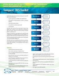
Pneumatic Features Dual Orifice Bubbler<br />
Tank<br />
Valve<br />
Tank 1 Tank 2<br />
Pump Desiccant<br />
Accubar<br />
1 Accubar<br />
2<br />
Vent<br />
Line 1<br />
Bypass<br />
Line 1<br />
Line 1<br />
Bringing the Benefits of Real-Time Data Collection to the World<br />
<strong>Sutron</strong> <strong>Corporation</strong>, 22400 Davis Drive, Sterling, Virginia 20164<br />
9<br />
Bypass<br />
Line 2<br />
Line 2<br />
Vent<br />
Line 2
Cabling<br />
Terminal Block<br />
Terminal Block Description Notes<br />
1 Earth Earth<br />
2 DATA SDI-12<br />
3 N/C NOT USED<br />
4 GND SDI-12<br />
5 RS485 A RS485 A<br />
6 RS485 B RS485 B<br />
7 +12V Power 12V (4 amps)<br />
8 GND Power Ground<br />
Power Connections<br />
The CF Bubbler requires external +12V power to operate. The most common power source for the Bubbler<br />
is a lead-acid battery. Connect the battery to pins 7 and 8 of the external terminal strip. Use wire that is<br />
at least 20 gauge and no longer than 5 feet. If you need longer wires to the battery, use a lower gauge wire.<br />
Make sure the power connections (7 and 8) go straight to the battery.<br />
When using the CF Bubbler with a Satlink or other telemetry device, be sure to still connect the battery<br />
directly to the Bubbler’s power connections.<br />
Note: you cannot connect the power to switched or protected voltages on most data loggers because the<br />
Bubbler uses too much power (around 4 amps at 12V) when it runs the pump.<br />
For details on Bubbler battery voltage please refer to page 31.<br />
SDI-12 Connections<br />
The SDI-12 interface is a three wire interface with connections for GND, Power and Data. However, most<br />
SDI-12 interfaces on data recorders cannot provide the 4 amps power needed to operate the bubbler pump.<br />
Therefore, do not connect the bubbler to the logger SDI +12V. Bubbler GND (Terminal 8) and +12V<br />
(Terminal 7) must always be connected directly to a battery or other high current source. If there are two<br />
batteries/power sources in the system, the grounds of these systems must be connected together.<br />
Connect the SDI Data line on the bubbler (pin 2) to the SDI Data line on the data logger. You may also<br />
connect the SDI GND line on the bubbler (pin 4) to the SDI GND line on the data recorder. The sensor is<br />
shipped to respond to SDI-12 address 0. The section SDI-12 Sensor Operation has details on the SDI-12<br />
protocol and supported commands.<br />
Note, if you are operating standalone, you do not need anything connected to the SDI-12 connections.<br />
Some older bubblers labels Terminal 3 as SDI +12V. Do not use this connection. The bubbler should<br />
only be powered using terminals 7 and 8. Newer units have removed this labeling/wiring to avoid<br />
confusion when installing a unit.<br />
- 10 -
DB9 Connector<br />
The Bubbler comes with a DB9F connector for connection to RS-232 devices. The DB9F can be connected<br />
to the serial port on most PCs using a straight cable. A null modem adapter is needed to connect to most<br />
PDAs and modems. There is a command line interface that allows communication via RS-232 (page 51).<br />
The following table shows the pin assignments in the DB9F connector.<br />
DB9F Pin Name Notes<br />
1 N/C No Connection<br />
2 RXD Data from CF Bubbler<br />
3 TXD Data to the CF Bubbler<br />
4 DTR Signal to the CF Bubbler<br />
5 Ground<br />
6 DSR<br />
Signal from unit, asserted as long as unit has<br />
power<br />
7 RTS Request to Send, signal to the CF Bubbler<br />
8 CTS Clear to Send, signal from the CF Bubbler<br />
Jumper J8 selectable for 5V (default) or VBAT<br />
9 VOUT (100ma max) - this line is usually NOT passed<br />
by a null modem<br />
Bringing the Benefits of Real-Time Data Collection to the World<br />
<strong>Sutron</strong> <strong>Corporation</strong>, 22400 Davis Drive, Sterling, Virginia 20164<br />
11
Quick Install<br />
• Mount the enclosure vertically<br />
• Install the orifice line(s) in the desired location(s)<br />
• Connect power<br />
• Do a leak test<br />
• Connect orifice line(s) to bubbler and Purge the line(s)<br />
• Customize settings:<br />
o Setup the orifice configuration (Dual Orifice Bubbler only)<br />
o Setup the bubble rate<br />
o Change station name<br />
o Set the water level<br />
o Set level units<br />
o Change automeasure schedule<br />
For complete installation details, please turn to page 60.<br />
Standalone Quick Install<br />
The Bubbler starts measuring and collecting data as soon as it is powered up. By default, the Bubbler will<br />
measure and log water level every 15 minutes; each reading is averaged for 10 seconds. All of these settings<br />
and more can be changed – please refer to page 24 to learn more about how the unit measures.<br />
Quick Install with a Logger<br />
Bubbler can be connected to other devices via either SDI-12, RS-485 and RS232.<br />
• For SDI-12 operation, connect the SDI data line on the Bubbler to a SDI logger and setup the logger<br />
to periodically collect data from the sensor. The first parameter of the M! command will provide<br />
the water level. For more details on SDI-12, please refer to the SDI-12 Sensor Operation section of<br />
the manual.<br />
• If connecting using the RS232 port, the data can be polled from the Bubbler, or it can be<br />
automatically output by the Bubbler. Setup the connected device (which may be a logger, a<br />
modem, or even a direct connection to a PC running HyperTerminal) for 115200 baud, 8 data bits,<br />
no parity (the baud rate can be changed via the front panel Setup > Other Settings > Baud Rate).<br />
• To poll for data, have the connected device issue a carriage return, wait for prompt, issue the<br />
ASCII command “!MEAS” followed by a carriage return, and capture the returned data. The<br />
first data item returned is the water level.<br />
• To capture data, setup the Bubbler for auto output via the front panel Setup->Other Settings-<br />
>Auto Output. Once setup, the Bubbler will periodically output the water level in ASCII.<br />
Please refer to the section RS232 Command Line Interface on page 51 for more details.<br />
Redundant Data Collection<br />
• Connect the Bubbler via SDI-12 to a logger and setup the logger to get data from the Bubbler.<br />
• Provide a power supply to the Bubbler (via the Battery connector).<br />
• With this setup, if the logger malfunctions, the Bubbler will keep on collecting data.<br />
- 12 -
Setup and Operation<br />
Principles of Bubbler Operation<br />
The Accubar CF Bubble is ideally suited for making water level measurements in rivers, streams, reservoirs,<br />
tidal, oceans and industrial areas.<br />
A bubble gauge operates by generating pressure in a line sufficient to produce bubbles out the end of tube<br />
placed in the water. When the rate of bubbles is sufficiently small, the pressure in the line is static so that the<br />
pressure at the orifice is the same as the pressure at the other end of the tube in the instrument itself. A<br />
sensor can then measure the pressure without having to install the sensor in the water.<br />
Pressure Maintenance<br />
Since air is always leaving the tank, the system will need to periodically operate the pump, just to keep the<br />
user pressures in the system balanced. Also, as the water level rises, the pump operates to balance the<br />
system at a higher pressure. As the water level goes down, the pump is not operated allowing the system to<br />
balance at a lower pressure as surplus air simply escapes through the line.<br />
Bubble Rate<br />
The bubble rate is the measure of the amount of air going down the orifice line per unit of time. The <strong>Sutron</strong><br />
Bubbler supports two units for bubble rate: Bubbles per minute (BPM) and Standard Cubic Centimeters per<br />
Minute (SCCM). The higher the bubble rate, the more air will flow down the line.<br />
The Bubbler rate can be configured by the user: use Station Setup > Bubbler Setup > Bubble Rate, SDI -12<br />
XBF, or BUBBLE RATE command line.<br />
The Dual Orifice Bubbler has two independent bubble rate settings, one for each line.<br />
The correct bubble rate is station dependent.<br />
• Sites measuring a deeper water level will require a higher bubble rate.<br />
If the bubble rate is too low, the Bubbler will not be able to overcome the pressure exerted by the water onto<br />
the air in the orifice line. This will result in no bubbles going out and an erroneous water level reading.<br />
A rapidly rising water level will not be immediately detected by the Bubbler. If a fast reaction time to water<br />
level changes is required, a higher bubble rate will be needed.<br />
• Sites with rapidly changing water levels will require a higher bubble rate.<br />
The higher the bubble rate, the more power the Bubbler will require.<br />
The bubble rate for a site with slowly changing levels is typically 60 bubbles per minute out of a 1/8 ID tube.<br />
This corresponds to a flow of about 5 standard cubic centimeters per minute (SCCM). The main device in<br />
the CF bubbler that governs the flow is a flow restrictor installed in the manifold. This flow restrictor is<br />
designed to give a specific flow based on the differential pressure it sees. For example, if there is a<br />
differential of 5 PSI across the restrictor, the flow will be 6 SCCM. At 10 PSI, the flow will be 12 SCCM.<br />
The way the bubbler maintains the flow at the desired value is to monitor this differential pressure and<br />
increase the pressure when it falls out of limit. The bubbler does this by turning on a pump to add pressure<br />
to a tank.<br />
The Dual Orifice Bubbler is equipped with two restrictor sensors and two tanks.<br />
Bringing the Benefits of Real-Time Data Collection to the World<br />
<strong>Sutron</strong> <strong>Corporation</strong>, 22400 Davis Drive, Sterling, Virginia 20164<br />
13
Note: the setting of the bubble rate is identical to how the bubble rate is set in conoflo type bubble gauges<br />
that have been used for many years.<br />
Pump Run Time<br />
The Bubbler tracks the cumulative pump on time. That is the total amount of time that the pump has been<br />
running. It is possible to reset the pump run time.<br />
Both the single and the Dual Orifice Bubbler are equipped with a single pump. The Dual Orifice Bubbler<br />
has two tanks and operates a valve in order to select which tank is being filled by the pump.<br />
To view the pump run time, go to Diagnostic > Pump Run Time, or. To reset the pump run time, press SET<br />
when viewing it via front panel, or type DIAGNOSTIC 0 via command line.<br />
Bubbler Internal Sensors<br />
The Bubbler uses several internal sensors to maintain pressure. There is a tank sensor, which measures the<br />
air pressure inside the tank, and a restrictor sensor, which measures the pressure drop across the internal<br />
restrictor. The sensors’ upper limit is 72.5PSI.<br />
The Dual Orifice Bubbler is equipped with two restrictor sensors but only one tank sensor. Which tank’s<br />
pressure is measured by the tank sensor is determined by the valve which selects what tank is being filled by<br />
the pump. Unlike the single Bubbler, the Dual Orifice Bubbler will not always be able to provide tank<br />
pressure to the user. If the Bubbler is busy filling tank 2, tank 1 pressure will be unavailable.<br />
Tank pressure can be found on the top level of the front panel menu. Both restrictor and tank pressure can<br />
be seen on the Diagnostic menu, via SDI-12 M8 and via INTERNAL command.<br />
Purge<br />
The purpose of the purge is to clear the orifice line of any obstructions, such as dirt and silt.<br />
Purging turns on the pump and builds to purge pressure (default 50 PSI) and then opens the restrictor bypass<br />
valve to force the pressurized air to the outlet. The pump will continue to run for purge duration, turn off,<br />
and allow the pressure to bleed out the line.<br />
To change purge pressure and duration, go to Station Setup > Bubbler Setup, or type PURGE PRESSURE<br />
and PURGE DURATION via command line.<br />
To start a purge, use Diagnostic > Purge, SDI-12 M9, PURGE NOW command line.<br />
The Dual Orifice Bubbler can purge each line independently. Purge information for each line is stored<br />
separately.<br />
During a purge, the Accubar will not be able to measure water level. This is because the pressure in the<br />
orifice line is not caused by the water, but by the Bubbler itself. You may see missing Accubar data or data<br />
marked ‘Reading old’ during a purge.<br />
AutoPurge<br />
A purge may be done automatically by the Bubbler. It can be done periodically, whenever the Bubbler<br />
detects a blockage, and whenever initiated by the user.<br />
If a Dual Orifice Bubbler is setup for an AutoPurge, it will purge line 1 first, and purge line 2 a short while<br />
afterwards. If a blockage is detected, only the blocked line will be purged.<br />
- 14 -
If you would like for the Bubbler to periodically purge, enable AutoPurge (Station Setup > Bubbler Setup ><br />
AutoPurge Enable or type AUTOPURGE ENABLE). To tell the Bubbler how often to purge, use the<br />
AutoPurge Interval setting.<br />
Blockage Detection<br />
Blockage detection refers to the Bubbler’s ability to automatically detect when the orifice line is blocked and<br />
initiate a purge, thus cleaning the line of the blockage. For example, if the line fills up with sand or silt, it<br />
could prevent the water level sensor from properly measuring the water level. The Bubbler can detect that<br />
condition and automatically purge the line of obstruction.<br />
When the orifice line is blocked, the pressure inside the line will build up. Initially, the Bubbler will think<br />
that the water level is rising and compensate by increasing the tank pressure. If this continues, the pressure<br />
in the line will increase to its upper limit and the system will stop pumping in order not to overpressure. To<br />
prevent this scenario, make sure to enable Bubbler’s blockage detection.<br />
If you would like for the Bubbler to automatically detect blockage and purge, enable Blockage Detection<br />
(Station Setup > Bubbler Setup > Blockage Detection or type BLOCKAGE DETECTION). Also setup<br />
Blocked Flow and Blocked Pressure.<br />
This is the algorithm that detects blockage: if the pressure across the Bubbler’s internal restrictor pressure<br />
sensor is less than the user set blocked flow, and if the pressure in the orifice line is greater than blocked<br />
pressure, a blockage has occurred.<br />
What this means is that if that the pressure inside the line (blocked pressure) is very high and the air<br />
flow through the line (blocked flow) is very low, the line is blocked.<br />
Set blocked pressure to a value that is higher than the highest pressure that can be caused by the water level<br />
being measured. If the blocked pressure is set too high, the system may never reach that pressure because<br />
the system tries not to overpressure (it will not operate the pump if the pressure is too high).<br />
Set blocked flow to a small value like 2PSI (which roughly corresponds to 2SCCM). The flow sensor is<br />
accurate to +/- 1PSI, and minimum flow is 5PSI (about 5SCCM). A small value indicates that not enough air<br />
is flowing through the line.<br />
For example, if blocked pressure is 15PSI and blocked flow is 2PSI, a purge will occur if the pressure in the<br />
orifice line is greater than 15PSI and the flow is less 2PSI.<br />
Please note that neither AutoPurge nor Blockage Detection can cause a purge more frequently than once an<br />
hour.<br />
Whenever a line is detected as blocked the event Line Blocked will be logged, along with the line pressure at<br />
the time. Similarly, whenever the Bubbler decides the line has cleared, it will place a Line Cleared event<br />
into the log.<br />
If a Dual Orifice Bubbler is setup for blockage detection, each line will be checked independently of the<br />
other. If a blockage is detected, only the blocked line will be purged. The note ‘Line Blocked’ refers to line<br />
1. The note ‘Line 2 Blocked’ refers to line 2. Blockage detection cannot be enabled for only one of the two<br />
lines.<br />
Leak Test<br />
Leaks inside the Bubbler can be a source of inaccuracy and/or excessive pumping and use of desiccant. To<br />
check for leaks, you must cap the outlet or orifice and run the built-in leak test.<br />
Bringing the Benefits of Real-Time Data Collection to the World<br />
<strong>Sutron</strong> <strong>Corporation</strong>, 22400 Davis Drive, Sterling, Virginia 20164<br />
15
<strong>Sutron</strong> provides a cap with each unit that can be used to cap the outlet for the leak test. When the leak test<br />
completes, the system will display a status indicating whether the unit has passed or failed the leak test along<br />
with a score.<br />
A Dual Orifice Bubbler can run leak tests on each line independently. Leak test information for each line is<br />
stored separately.<br />
To start a leak test, use Diagnostic > Leak Test, or LEAK TEST via command line.<br />
Starting the Bubbler<br />
The Bubbler starts operating as soon as power is applied. The display will turn on. If an Accubar is<br />
installed, measurement will commence and the front panel will be updated with a water level reading.<br />
While the bubbler is operating, the status LED will flash occasionally to let you know that the bubbler is<br />
operational.<br />
Green LED flashes every five seconds to indicate the Bubbler is operating normally<br />
Red LED flashes if the Bubbler has encountered a problem<br />
Dual Orifice Bubbler Configuration<br />
This section refers to the Dual Orifice Bubbler, which is an enhanced version of the CF Bubbler that is<br />
capable of providing redundant measurements, measuring water level in two separate bodies of water,<br />
accurately measuring water density, or providing an extended range of water level measurement.<br />
The setting Orifice Config setting determines how the dual orifice bubbler behaves. The options are Single,<br />
Dual Separate, Dual Density, and Dual Expanded Range. It is paramount that this setting be configured<br />
properly for the station.<br />
Please remember that the Dual Orifice Bubbler comes in three versions: -1 which has only one Accubar<br />
sensor installed, -2 which has two Accubar sensors for measuring water level, and -3 which has one sensor<br />
for water level and another for density. The -1 and -2 sensors can be configured for any Orifice Config. The<br />
-3 can only be used in Dual Density mode. Information about the second sensor (No Accubar Found, Stage,<br />
Density) can be found in the Diagnostics menu and via the DIAG command.<br />
To setup Orifice Config, use Station Setup > Dual Orifice Setup > Orifice Config, or ORIFICE CONFIG<br />
command.<br />
Single<br />
In this mode, the Dual Orifice Bubbler acts like a single Bubbler. Only line one is utilized, and some of the<br />
power of the unit is wasted.<br />
Dual Separate<br />
The device monitors and manages the pressure on each orifice line independently of the other so that<br />
pressures in one line do not affect the operation of the other line. They can be used to make measurements in<br />
separate channels or bodies of water or within the same area as redundant sensors.<br />
In this mode, Bubbler will produce two water level readings (see page 19). Stage 1 is measured in line one,<br />
and Stage 2 is measured in line 2.<br />
Dual Density<br />
This mode is used when the density of the water is of interest to the user. The Bubbler will compute density<br />
and use the result in the water level computation. Please see page 19 for more on density.<br />
- 16 -
In this mode, the tube endings have to be installed in a vertical configuration, with line 1 above line 2. Line<br />
2 must be the deeper line for the system to operate properly. The distance between the tubes must not<br />
change if the density reading is to be correct. Please see page 19 for more on Orifice Separation.<br />
In Dual Density mode, stage is measured on line one.<br />
Dual Expanded Range<br />
In order to measure water deeper than the range of a single Accubar sensor (please see specifications on page<br />
79), the Dual Orifice Bubbler can be put into dual expanded range mode. Expanded mode can offer up to<br />
twice the range of a single Accubar.<br />
In this mode, tube connected to line one is placed in shallower water, and line two in deeper water. The<br />
basic principle is that the Bubbler will measure water level using line one in shallower water until that line is<br />
almost out of water. Once the water level drops, the Bubbler will use the sensor in line two which is in<br />
deeper water. If the water level were to rise such that the sensor in line two in deeper water were overpressured,<br />
the Bubbler would switch to using the sensor in line one in shallower water.<br />
Please note that in this mode, the Bubbler will not make any measurements until the user sets the water level.<br />
See page 20 for more details on Dual Expanded mode.<br />
Accubar Pressure Sensor<br />
The Accubar is a pressure sensor inside the Bubbler. It is used to measure the pressure in the orifice line.<br />
That pressure can be translated into a water level reading.<br />
The true reading made by the Accubar is a differential pressure – the pressure difference between<br />
atmospheric pressure and pressure in the orifice line. The Accubar is a vented sensor.<br />
Each Accubar sensor is calibrated independently of the Bubbler. On each Accubar there is a sensor, an<br />
analog to digital converter, and a secure chip containing the calibration data. Every Accubar has a unique<br />
sensor ID.<br />
The Dual Orifice Bubbler may come equipped with two Accubar sensors. The -1 version of the Dual Orifice<br />
Bubbler comes with only one sensor. In order to measure pressure on both lines, the -1 Dual Orifice Bubbler<br />
needs to switch the single Accubar between the two lines. Every switch will cause a delay of up to one<br />
minute as the pressures in the system are equalized prior to the measurement.<br />
The more capable -2 version of the Dual Orifice Bubbler has two Accubar sensors, each setup to measure<br />
pressure in its own line. It can make fast water level readings with fewer disturbances to the pressure in the<br />
lines.<br />
The -3 version of the Dual Orifice Bubbler features an Accubar sensor built to measure density via the<br />
pressure differential between the two lines. Note that both the -1 and -2 versions of the Dual Orifice Bubbler<br />
can also measure density, but not with the accuracy of the -3 version.<br />
To view the Accubar ID, use Diagnostic > Accubar ID, SDI-12 XAI, or DIAGNOSTIC via command line. If<br />
there is more than one Accubar in the system, use SDI-12's XAI2 command. Over command line and front<br />
panel, both Accubar IDs will show automatically. Additionally, the function of the second Accubar (Stage<br />
or Density) will also be displayed.<br />
The Accubar is a plug and play part, meaning that it can be easily replaced without disturbing the rest of the<br />
Bubbler system.<br />
Disabling the Accubar and water level measurements can only be accomplished by physically disconnecting<br />
the sensor from the board. Before you disconnect the Accubar, please consider the fact that the Accubar is a<br />
Bringing the Benefits of Real-Time Data Collection to the World<br />
<strong>Sutron</strong> <strong>Corporation</strong>, 22400 Davis Drive, Sterling, Virginia 20164<br />
17
very low power device that does not interfere with the pressure maintenance of the Bubbler. Plus, the<br />
Accubar will provide water level data which may be of use if the external sensor fails.<br />
Autozero<br />
Even though the Accubar sensor is very accurate and stable, it still exhibits a small amount of drift in the<br />
"zero". A sensor's accuracy depends completely on the stability of the zero and span. Any error in the zero<br />
becomes an error in the final water level. Even though sensors are calibrated at the factory for zero, they all<br />
drift and introduce error into the water level. The CF Bubbler Accubar features an autozero ability that<br />
eliminates the errors due to a drift in zero resulting in more accurate water level readings.<br />
The Bubbler will automatically autozero the Accubar at the end of a purge. The autozero will take<br />
approximately half a minute to complete. During this time, the sensor is vented to the atmosphere so that<br />
both sides of the sensor are at identical atmospheric pressure. The Bubbler can be asked to do an autozero<br />
via command line, front panel or SDI-12. Bubbler software versions older than 1.30 featured an automatic<br />
autozero every 15 minutes.<br />
To view the Accubar autozero, use SDI-12 V, or DIAGNOSTIC via command line. If Log Daily Values is<br />
enabled, the autozero result will be logged every day.<br />
There are several ways to access the water level reading without the autozero: diagnostic menu called<br />
Accubar Pressure Diagnostic, two SDI-12 commands (M1, M2), Modbus access. Additionally, if Log<br />
Accubar Pressure is enabled, the logged pressure does not include autozero.<br />
Measuring Water Level (Stage)<br />
The Bubbler uses the Accubar sensor to measure water level. If no Accubar is installed, the water level will<br />
not be measured. The water level is the first reading shown on the front panel when the station is powered<br />
up.<br />
The Accubar is a pressure sensor. It will measure the difference between the pressure in the orifice line and<br />
atmospheric pressure. Water level is computed from that pressure difference. The Bubbler will take<br />
multiple Accubar samples and compute an averaged water level from them.<br />
Quality of Measurement<br />
If there is a problem when measuring, the quality of the water level will be bad. If using the front panel, a<br />
bad quality is indicated with a “?” after the reading. Additional details on the error may be available (see<br />
below). The command line interface will say ‘error’ and indicate the type of problem, .SDI-12 will indicate<br />
an invalid reading. The red LED will blink if the last reading is invalid.<br />
Starting with version 1.35, some bad readings may show up as -999.9. This kind of reading indicates a<br />
complete failure to make a meaningful measurement. Sometimes, the unit will be able to salvage an<br />
imperfect reading and produce a reasonable result. For example, if fewer than the expected number of<br />
samples were averaged, or if the battery voltage were low, the result may still be representative of the water<br />
level. However, if the Accubar sensor failed to measure the pressure, -999.9 would be reported as the result.<br />
Starting with version 1.37 additional error details will be provided by the Bubbler. If there was an error in<br />
the reading, one of the following will display on command line and front panel:<br />
• Sensor Failure – this means that there is either a problem with the Accubar sensor or in the<br />
communications line leading to the sensor.<br />
• Battery Low – the battery voltage was under an acceptable threshold. The reading may still be<br />
correct.<br />
• Missing Readings – the system did not collect the expected number of samples when averaging a<br />
stage reading. In continuous mode, the first reading after power-on is likely to have missing<br />
readings.<br />
• Line out of water? – Dual Orifice Bubbler in Density mode may log this error if one of the two<br />
lines was out of water (technically, pressure in either line was less than 0.1PSI)<br />
- 18 -
• Bad Orifice Separt? – Dual Orifice Bubbler in Density mode may log this error if the computed<br />
density in is out of range of 0.9 and 1.1gm/ml. This is most likely to the system having an<br />
incorrectly setup Orifice Separation. The Orifice Separation needs to be set to the exact distance<br />
between the two lines. It can be computed by the system if the user knows the exact density of<br />
water.<br />
Right after power up, while the Bubbler is still computing the first reading, the message ‘calculating’ will<br />
show on the front panel and command line interface. Please give the Bubbler a minute after power up to get<br />
going.<br />
If the Sensor Failure is reported repeatedly, it is most likely due to failure of the Accubar sensor. In this<br />
case, the Accubar sensor may need to be replaced (see page 69).<br />
The Dual Orifice Bubbler may be setup to produce two water level measurements – please see the section<br />
below.<br />
Setting the Water Level<br />
To see the water level, use the first menu shown on the front panel; Via command line, use the MEAS<br />
command. Via SDI-12, use the M command. If a Dual Orifice Bubbler is setup to produce two water level<br />
readings, each of the interface points just mentioned will provide the second water level reading. The front<br />
panel will provide ‘stage’ and ‘stage 2’ readings. If setup for density, the front panel will show a ‘density’<br />
reading. The SDI-12 M and command line MEAS command will return more parameters relevant to the<br />
second reading.<br />
Dual Orifice Bubbler Second Measurement<br />
The Dual Orifice Bubbler may produce two readings. If Orifice Config is setup as Dual Separate, then<br />
Bubbler will produce two water level readings. If it is setup as Dual Density, Bubbler will produce one<br />
water level and one density reading.<br />
If setup for two water level readings, the reading for line one will be labeled stage and the water level<br />
reading for line two will be stage2. If the measurement name has been changed from stage, then the second<br />
reading’s name will have ‘2’ appended to it, e.g. if measurement name is ‘water’ the second reading will be<br />
displayed and logged as ‘water2’.<br />
Stage is measured in line one, and Stage 2 is measured in line two.<br />
Please note that you may not setup the Bubbler to make two stage readings and a density reading.<br />
Dual Orifice Bubbler Density<br />
In Orifice Config Dual Density mode, in addition to measuring the water level in line one, the Bubbler will<br />
measure the density of water. The resultant density will be used to modify the water level reading. Density<br />
will be shown on the front panel and placed into the log. It may also be accessed via SDI-12 and command<br />
line.<br />
In this mode, the tube endings have to be installed in a vertical configuration, with line 1 above line 2. Line<br />
2 must be the deeper line. Stage is measured on line one while the density is measured by the differential<br />
pressure of line 1 and line 2. Please see the installation section on page 60 for more details.<br />
Dual Orifice Bubbler has settings called Orifice Separation and Separation Units. Orifice Separation is the<br />
exact vertical distance between the two tube endings. The Bubbler will need to be told either the Orifice<br />
Separation or the current density in order to produce correct water level and density readings.<br />
Density is computed based upon the measured pressure difference between the two orifice lines and the user<br />
settings Orifice Separation and Separation Units. Density is reported in units of gm/ml.<br />
Density = (Pressure Difference)/(Orifice Separation in feet)*2.3066587<br />
Bringing the Benefits of Real-Time Data Collection to the World<br />
<strong>Sutron</strong> <strong>Corporation</strong>, 22400 Davis Drive, Sterling, Virginia 20164<br />
19
Once computed, the resultant density will be included in the computation of water level.<br />
Water Level in feet = (Accubar Pressure in PSI *2.3066587) / Density<br />
+ Field Calibration Offset<br />
Calibrating Density<br />
The Bubbler can help determine the correct Orifice Separation:<br />
• While viewing a live density reading on the front panel, press SET.<br />
• If you Bubbler is equipped to measure water temperature, it will ask if the lines are in pure water. If<br />
so, the Bubbler can correctly determine the density based on water temperature, and it can compute<br />
the exact Orifice Separation.<br />
• Alternatively, the correct density can be entered via the front panel, and the Bubbler will use that<br />
value to compute and set the Orifice Separation.<br />
• Via command line, type DENSITY = 1 to set Density to 1. If your Bubbler can measure water<br />
temperature and the lines are in pure water, type DENSITY = PURE.<br />
The -3 version of the Dual Orifice Bubbler features an Accubar sensor dedicated to measuring density. Note<br />
that both the -1 and -2 versions of the Dual Orifice Bubbler can also be setup measure density, but not with<br />
the accuracy of the -3 version. Please note that you may not setup the Bubbler to make two stage readings<br />
and a density reading.<br />
Density readings are only valid if the resultant density is between 0.9 and 2.0 gm/ml. Additionally, the<br />
pressure in each line must be at least 0.1 PSI. If these conditions are not met, the Bubbler will log a ‘Out of<br />
Range’ error with each density reading. The front panel and command line interfaces will indicate the error.<br />
Separation Units are units of length (feet, inches, meters, centimeters, or millimeters). They tell what units<br />
Orifice Separation is expressed in. Changing the Separation Units will not automatically change the Orifice<br />
Separation.<br />
To set the density via front panel, power up the Bubbler, press the DOWN key until the density reading is<br />
shown, and the press SET. Enter the correct density and press set again. The system will use the entered<br />
value to compute the Orifice Separation. It is also possible to use SDI-12 XS command and command line<br />
DENSITY to set the density.<br />
Optionally, one may access Orifice Separation and Separation Units directly via via Station Setup > Dual<br />
Orifice Setup, via SDI-12 XE, or via ORIFICE SEPARATION and SEPARATION UNITS commands.<br />
New Log Entry Error<br />
Please note a new log entry error: Out of range – Dual Orifice Bubbler in Density will LOG this error for<br />
either of these conditions:<br />
• One of the two lines was out of water (technically, pressure in either line was less than 0.1PSI)<br />
• If the computed density in is out of range of 0.9 and 2.0gm/ml. This is most likely to the system<br />
having an incorrectly setup Orifice Separation.<br />
If your Dual Orifice Bubbler is equipped to measure water temperature, please make sure to read the section<br />
on water temperature and suspended sediment.<br />
Dual Orifice Bubbler Expanded Range Mode<br />
In order to measure water deeper than the range of a single Accubar sensor (please see specifications on page<br />
79), the Dual Orifice Bubbler can be put into dual expanded range mode. Expanded mode can offer up to<br />
twice the range of a single Accubar.<br />
In this mode, tube connected to line one is placed in shallower water, and line two in deeper water. The<br />
basic principle is that the Bubbler will measure water level using line one in shallower water until that line is<br />
almost out of water. Once the water level drops, the Bubbler will use the sensor in line two which is in<br />
- 20 -
deeper water. If the water level were to rise such that the sensor in line two in deeper water were overpressured,<br />
the Bubbler would switch to using the sensor in line one in shallower water. Please see the<br />
installation section on page 60 for more details.<br />
Please note that in this mode, the Bubbler will not make any measurements until the user sets the water<br />
level. Read on for detail on how to setup the station.<br />
Consider this example<br />
• A lake has a high water level line of 80 feet. A standard 25PSI Accubar (see specifications) can<br />
measure up to 57 feet of water. In order to measure the full water level, a Dual Orifice Bubbler<br />
needs to be installed.<br />
• Line one has been placed at the 50 foot water line. Without the filed calibration offset, line one<br />
would provide a reading of 30 feet when the water line is at the maximum of 80 feet, and a reading<br />
of 0 feet when the water line drops below 50 feet.<br />
• Line one needs to have its field calibration offset set to 50 feet, indicating that whatever water<br />
level it measures it needs to add 50 feet to it. Line 1 will be able to measure the water level until it<br />
drops below 50 feet at which point the line would be physically out of the water.<br />
• Line two has been placed at the bottom of the lake. In this setup, the line needs no offset (field<br />
cal 2 = 0). However, since a standard 25PSI Accubar can only measure up to 57 feet of water, it<br />
will not be able to provide a reading once the water level reaches 57 feet.<br />
• The Dual Orifice Bubbler will automatically switch from using line one to using line two once the<br />
water level drops below about 52 feet.<br />
• As the water level rises above about 55 feet, the Dual Orifice Bubbler will automatically switch<br />
from using line two to using line one.<br />
• When the water level is between 50 and 57 feet, either line can make the measurement. When it is<br />
above 57 feet, it is too deep for line two, and when it is below 50 feet, line one is in the air and<br />
above the water line.<br />
If the pressure for line one in shallower water drops below 1PSI, the system will switch to using line two in<br />
deeper water. One PSI is roughly equivalent to 2.3 feet of water.<br />
The Bubbler will measure the water in line two in deeper water until the pressure is greater than the line<br />
switch limit. After reaching the line switch limit, the system will switch to using line one in shallower<br />
water.<br />
Line Switch Limit PSI = 2PSI +<br />
Absolute value(Field Calibration Offset PSI– Field Cal 2 PSI)<br />
A line switch may be initiated whenever any water level measurement is made. If the measurement does<br />
cause a line switch, the next measurement will be made in the line switched to. Each switch will be<br />
accompanied by a log entry Line Switch that will indicate the line switched to.<br />
Active Line<br />
The line that is currently being used by the Bubbler to measure the water level is referred to as the active<br />
line. The front panel and the command line interface will indicate which line is currently active.<br />
On the front panel, the main stage menu will show the active line after the stage reading; e.g.<br />
Stage (line 1)<br />
10.1ft<br />
On the command line interface, type STATUS and the system will report the active line.<br />
The front panel will also indicate details on the inactive line. Shown right below the stage menu, the inactive<br />
line menu shows the pressure in the inactive line, as measured using the restrictor and tank pressure sensors.<br />
Bringing the Benefits of Real-Time Data Collection to the World<br />
<strong>Sutron</strong> <strong>Corporation</strong>, 22400 Davis Drive, Sterling, Virginia 20164<br />
21
These sensors are far less accurate than the Accubar. Please note that this reading will not be possible<br />
during a purge or other similar line pressure disturbance.<br />
If the line pressure computed is not too high to be measured by the Accubar, the user can press SET to<br />
switch the currently active line, which will result in the Accubar measuring the water level in that line. After<br />
the user initiates a line switch, the system will not do another line switch for three minutes. After the three<br />
minutes are up, the system will line switch only if the normal criteria described previously are met.<br />
How does the Bubbler know which line is in deeper water? It needs the help of the user. The field<br />
calibration offset of the shallower line should be setup to be greater than that of the deeper line.<br />
Pressure is maintained in both lines at all times.<br />
Accubar sensors are protected by a relief valve from excessive pressure.<br />
The Bubbler is will switch the Accubar out of line to prevent it from being exposed to excessive pressure.<br />
No line switch will occur if a line is blocked (which can happen only if Blockage Detection is enabled).<br />
The system will produce only one water level reading in expanded mode.<br />
Setting Water Level in Dual Expanded Range Mode<br />
The Bubbler will not measure the water level until it has been calibrated in Dual Expanded Range mode. It<br />
is mandatory that the user go through the process of setting the water level after installation.<br />
To set the water level via front panel, power up the Bubbler, and see the message Stage Not Set. Press SET.<br />
Enter the correct water level for line one and press SET again. The system will inform you of the computed<br />
field calibration offset. Next, enter the stage for line two and press SET. The system will show the new offset<br />
for line two.<br />
• If either line is too deep for the Accubar sensor, the system will ask for a field calibration offset<br />
instead of the water level.<br />
• If the line is above the water level, enter the level of the water at the point where the line is<br />
installed.<br />
It is also possible to use SDI-12 XS command and command line LEVEL 1 and LEVEL 2 to set the water<br />
level.<br />
An alternative way of calibrating the station, is to change the field calibration offset directly. You must<br />
change the offset for both lines before the system will start collecting water level data.<br />
Measurement Name<br />
The reading made by the Bubbler is that of water level. This manual refers to the reading as ‘water level’<br />
There is a setting called measurement name that allows the user to name the reading something else, such as<br />
‘stage’.<br />
The user chosen name will appear in the log, on the front panel, and via the command line interfacel.<br />
Measurement name can be viewed and changed via Station Setup > Accubar Setup or via the<br />
MEASUREMENT NAME command line.<br />
The Dual Orifice Bubbler may produce two water level readings. To differentiate the two, the number 2 is<br />
appended to the user set name. If ‘stage’ was the user chosen name, then the readings will be labeled ‘stage’<br />
and ‘stage2’.<br />
Setting Water Level<br />
When the Bubbler is first installed, it will display an absolute water level based on the water pressure. The<br />
user will then typically read the current water level off a staff gauge and then set this level into the Bubbler.<br />
To set the water level via front panel, power up the Bubbler, wait for it to show a water level reading, and<br />
the press SET. Enter the correct water level and press set again. It is also possible to use SDI-12 XS<br />
- 22 -
command and command line LEVEL to set the water level. Dual Orifice Bubbler supports the LEVEL 2<br />
command.<br />
For more details on setting the density for the Dual Orifice Bubbler in Dual Density mode, please see the<br />
section on page 19. Dual Expanded mode is detailed on page 20.<br />
Field Calibration Offset<br />
Water Level = Accubar reading in chosen units + Field Calibration Offset<br />
The field calibration offset can be viewed and changed via Station Setup > Accubar Setup, via SDI-12 XE, or<br />
via FIELD CAL OFFSET command.<br />
The Dual Orifice Bubbler can be placed into Dual Separate or into Dual Expanded Range mode. In those<br />
cases, each line will have its own field calibration offset. The offset for the second line can be accessed in<br />
the same way as the offset for the first line: front panel, SDI-12, and the command line.<br />
Level Units<br />
Bubbler can report water level readings in feet, PSI, kPa, centimeters, meters, millimeters, or user units.<br />
Water Level = Accubar reading in chosen units + Field Calibration Offset<br />
To change level units, use Station Setup > Accubar Setup > Level Units, SDI-12 XUP, or LEVEL UNITS<br />
command.<br />
User units are defined using the fields User slope and user offset. If user units are chosen:<br />
Water Level = (Accubar reading in PSI * user slope) + user offset + Field Calibration Offset<br />
To change user slope and offset, use Station Setup > Accubar Setup > User Slope, SDI-12 XUU, or USER<br />
SLOPE and USER OFFSET commands.<br />
The Dual Orifice Bubbler will use the same units for both level readings.<br />
Right Digits<br />
The number of digits shown after the decimal place is referred to as the right digits. If you would like the<br />
water level to read 10.12 rather than 10.12345, please set the right digits to 2.<br />
To change right digits, use Station Setup > Accubar Setup > Right Digits, SDI-12 XUP, or RIGHT DIGITS<br />
command.<br />
The Dual Orifice Bubbler will use the same right digits for both level readings.<br />
Log Temp in Box<br />
The Accubar sensor has an internal temperature sensor. Please keep in mind that this is the temperature<br />
inside the Bubbler which is not the same as the temperature outside. The temperature is displayed in user’s<br />
choice of Celsius or Fahrenheit. Temperature may be logged along with stage.<br />
To view Accubar temperature, use Diagnostic > Accubar w/o offset , SDI-12 M6, or use the MEAS<br />
command. To change Accubar temperature units, use Station Setup > Accubar Setup, SDI-12 XUT, or<br />
TEMP UNITS command. To enable logging temperature, use the Station Setup > Accubar Setup menu.<br />
The Dual Orifice Bubbler may come equipped with two Accubar sensors. While it is meaningful to report<br />
two water level readings, it is not useful to have two readings of the temperature inside the Bubbler. Most<br />
Bringing the Benefits of Real-Time Data Collection to the World<br />
<strong>Sutron</strong> <strong>Corporation</strong>, 22400 Davis Drive, Sterling, Virginia 20164<br />
23
eported temperature readings will be from the first Accubar sensor. That being said, the temperature of the<br />
second sensor can still be viewed diagnostic purposes: use Diagnostic > Accubar w/o offset , SDI-12 M6.<br />
Automeasure<br />
Automeasure refers to the Bubbler’s ability to automatically measure and log water level data. The user can<br />
determine when this will occur by changing the automeasure interval and time. Automeasure may not be<br />
turned off.<br />
Automeasure time and interval determine when the Bubbler measures and logs data.<br />
• E.g. Automeasure time 00:00:00 interval 00:10:00<br />
• 00:10:00 data measured and logged<br />
• 00:20:00 data measured and logged<br />
• 00:30:00 data measured and logged<br />
• and every ten minutes afterwards…<br />
• E.g. Automeasure time 00:00:30 interval 00:05:00<br />
• 00:00:30 data measured and logged<br />
• 00:05:30 data measured and logged<br />
• 00:10:30 data measured and logged<br />
• and every five minutes afterwards...<br />
To change automeasure interval and time, use Station Setup > Accubar Setup, or AUTOMEASURE<br />
INTERVAL and ATUOMEASURE TIME commands.<br />
The last measurement made by automeasure is called last automeasured– please see page 25.<br />
Operating Mode<br />
There are two operating modes: normal and continuous:<br />
• In normal mode, Bubbler spends its time in low power mode until it is time to measure. Once the<br />
measurement is complete, Bubbler goes back to low power mode. This is the most commonly used<br />
mode and is recommended unless the Bubbler will be measuring very frequently.<br />
• In the continuous mode, Bubbler is constantly collecting data. When it is time to measure, Bubbler<br />
will use the previously collected data to instantly come up with a water level reading. Bubbler does<br />
not go into low power in continuous mode. The continuous mode adds about 10 mA to the<br />
quiescent power consumption compared with 0.25mA in the normal mode.<br />
These examples illustrate the difference between continuous and normal modes:<br />
Normal mode with 10 second averaging:<br />
1. 12:00:00 measure command is received (via SDI-12, front panel, RS232, or automeasure)<br />
2. 12:00:00 sensors are powered on and measurement starts<br />
3. 12:00:11 measurement completes with data collected between 12:00:00 and 12:00:10<br />
4. 12:00:11 sensors are powered down<br />
Continuous mode with 10 second averaging (sensors are powered on all the time):<br />
1. 12:00:00 measure command is received (via SDI-12, front panel, RS232, or automeasure)<br />
2. 12:00:00 measurement completes with data collected from 11:59:50 to 12:00:00<br />
Desired Effect Appropriate Mode<br />
Low power consumption Normal mode<br />
Low power consumption and immediately ready data Normal mode, use last measured readings (page 25)<br />
Immediately ready and current data Continuous mode<br />
Very frequent measurements (every 15 seconds or less) Continuous mode<br />
Operating mode can be changed via front panel Station Setup > Accubar Setup, via SDI-12 XOM and via<br />
OPERATING MODE command line<br />
- 24 -
Averaging Time<br />
Every time the Bubbler measures it will collect samples for a user defined period in order to produce a water<br />
level reading: this time period is called the averaging time. The setup variable avg time controls the<br />
averaging time. It is not possible to specify a number of samples, only the averaging time.<br />
Averaging time can be changed via front panel Station Setup > Accubar Setup, via SDI-12 XT, and via AVG<br />
TIME command line.<br />
Last Automeasured<br />
Water level measurements made by the Bubbler are not instantaneous; how long they take depends on<br />
averaging time (page 25). When a logger is communicating with the Bubbler, it can ask the Bubbler to make<br />
a new measurement. However, the logger then has to wait for the Bubbler to complete the measurement.<br />
If the user desires data that is instantly available, the Bubbler provides last measured data. The Bubbler<br />
automatically measures based on the automeasure interval (see page 24) . That data can be retrieved as the<br />
last measured data.<br />
For example, if Bubbler is setup to automeasure every 10 minutes, with an averaging time of 10 seconds:<br />
12:00:00 to 12:00:10 Bubbler measures water level<br />
12:01:00 logger asks for last measured data; Bubbler immediately returns 12:00:10 data<br />
12:10:00 to 12:10:10 Bubbler measures water level<br />
12:11:00 logger asks for last measured data; Bubbler immediately returns 12:10:10 data<br />
If the user desires data that is both immediately available and current, continuous mode (page 24) is the way<br />
to go.<br />
Last measured data can be accessed via SDI-12 M3 and via LAST command.<br />
Water Temperature<br />
Certain models of the Bubbler are capable of measuring a water temperature sensor. Such Bubblers will<br />
have an external five pin connector that the sensor can be wired to. Thermistor and Platinum RTD type<br />
sensors can be connected to the Bubbler.<br />
If a Bubble is equipped with the hardware for measuring a water temperature sensor, it will automatically<br />
measure and log water temperature every time it measures water level.<br />
Live water temperature readings will be shown on the front panel. After turning on the front panel, press<br />
DOWN until the Water Temp menu shows. Additionally, the water temperature can be accessed via SDI-12<br />
M4 and M5 and command line. All settings relating to water temperature can be found via the front panel<br />
in Station Setup > Water Temp Setup.<br />
• If the Bubbler is not equipped for measuring water temperature, no front panel menus relating to water<br />
temperature will appear.<br />
• To disable water temperature readings, please use the Water Temp Enable setting. It is not enough to<br />
just disconnect the water temperature sensor!<br />
• Water temperature may be used in the computation of suspended sediment.<br />
Water temperature readings are logged with the Water Temp label. Water temperature can be reported in<br />
Celsius or Fahrenheit units, as dictated by the Temp Units setting.<br />
Water Temperature Sensors<br />
Two main types of water temperature sensors can be connected to the Bubbler:<br />
o Platinum RTD<br />
o NTC Thermistor<br />
Bringing the Benefits of Real-Time Data Collection to the World<br />
<strong>Sutron</strong> <strong>Corporation</strong>, 22400 Davis Drive, Sterling, Virginia 20164<br />
25
After wiring the sensor, make sure to tell the Bubbler what kind of sensor it is via the Water Temp Type<br />
setting. The following options are available:<br />
• Platinum 385<br />
• Platinum 392<br />
• Platinum Custom<br />
• NTC Thermistor<br />
Platinum RTD<br />
If Platinum 385 or Platinum 392 are chosen as the Water Temp Type, no further setup is needed. If Platinum<br />
Custom is chosen, then the coefficients C0, C1, and C2 need to be entered. The following equation tells how<br />
temperature is computed<br />
R<br />
T = C0<br />
− C1+<br />
C2<br />
R0<br />
T is the temperature in Celsius.<br />
C0, C1, and C2 are the coefficients and they are sensor dependent. These are Bubbler setup variables.<br />
R is the resistance of the sensor element in Ohms which is measured by the Bubbler.<br />
R0 is the resistance of the sensor at 0 degrees Celsius. It is also a Bubbler setup variable. It is traditionally<br />
100 Ohms. When the temperature is calibrated, this value is affected.<br />
The table below describes the coefficients used by the predefined Water Temp Type:<br />
Coefficien<br />
t<br />
Platinum<br />
385<br />
Platinum<br />
392<br />
C0 3383.8095 3389.7946<br />
C1 13181769 13194682<br />
C2 -1731602 -1703975<br />
NTC Thermistor<br />
For NTC Thermistor sensor types, the Steinhart–Hart equation coefficients need to be entered. Temperature<br />
is computed using this equation:<br />
1<br />
3<br />
= A + B ln( R)<br />
+ C(ln(<br />
R))<br />
T<br />
T is the temperature in Kelvins.<br />
R is the resistance of the sensor element in Ohms which is measured by the Bubbler.<br />
A, B, and C are the coefficients. The Bubbler refers to them as Stein A, Stein B, and Stein C.<br />
Water Temperature Sensor Wiring<br />
The connector wiring pins are as follows:<br />
1. Earth Ground<br />
2. Force-<br />
3. Sense-<br />
4. Sense+<br />
5. Force+<br />
Two Wire Sensor<br />
Connect sensor leads to positions 3 & 4. Use two short pieces of wire to jumper position 2 to 3 and 4 to 5.<br />
Four Wire Sensor<br />
Connect sensor GND and Sense- to positions 2 & 3 respectively. Connect sensor Sense+ and V+ to positions<br />
4 & 5 respectively.<br />
- 26 -
Calibrating Water Temperature Sensors<br />
The easiest way to calibrate the water temperature sensor is via the front panel. First, navigate to the menu<br />
that says Water Temp. Press SET, and then enter the correct temperature reading.<br />
Density Computed From Water Temperature<br />
The density of water can be computed as a function of water temperature using the equation below:<br />
T + 288.<br />
9414<br />
density = 1000(<br />
1−<br />
( T − 3.<br />
9863)<br />
508929.<br />
2 * ( T + 68.<br />
12963)<br />
density is the density of water as a function of temperature in kg/m^3<br />
T = temperature in C<br />
The Bubbler calls this value Density Temp and it can be accessed via the DIAG command, via the<br />
Diagnostic front panel menu, and via the SDI-12 M4 and M5 commands.<br />
Suspended Sediment<br />
A -3 dual orifice Bubbler with a water density sensor and a water temperature sensor will automatically<br />
compute suspended sediment. Suspended sediment is computed as a function of measured water density and<br />
water temperature.<br />
A live reading of suspended sediment is shown on the front panel. Press DOWN several times until a menu<br />
labeled Suspended Sediment shows up. SDI-12 M4 and M5 commands can be used to access the suspended<br />
sediment measurement. On the command line., MEAS and LAST commands will show suspended sediment<br />
readings along with the rest of water data. Alternatively, type SUSPENDED MEASUREMENT on the<br />
command line.<br />
• The Bubbler expresses suspended sediment in units of mg/L.<br />
• Suspended sediment will be logged with every water level reading.<br />
• Suspended sediment is dependent on density and water temperature readings. If either of those<br />
fails, so will the suspended sediment reading.<br />
• A correctly set Orifice Separation is critical for getting accurate suspended sediment readings.<br />
Please see the section on Density for details.<br />
• The only way to disable suspended sediment computations and logging is to disable the Water Temp<br />
Enable setting. Please note that only -3 dual orifice Bubblers are capable of measuring suspended<br />
sediment.<br />
Calibrating Suspended Sediment<br />
If you know the current suspended sediment, you may calibrate the Bubbler's Orifice Separation setting. To<br />
do so, press SET while viewing the live reading of Suspended Sediment on the command line. Alternatively,<br />
type SUSPENDED SEDIMENT = 1000 on the command line to set it to 1000mg/L.<br />
Logging<br />
A secure flash chip in the Bubbler provides a logging capacity of more than 300,000 entries. Data will not<br />
be lost if power is removed. Once the log is full, the oldest data will be overwritten.<br />
Bringing the Benefits of Real-Time Data Collection to the World<br />
<strong>Sutron</strong> <strong>Corporation</strong>, 22400 Davis Drive, Sterling, Virginia 20164<br />
27<br />
2<br />
)
Each log entry consists of<br />
• date and time (with a second resolution)<br />
• name (e.g. Water Level)<br />
• measurement reading (optional)<br />
• measurement quality and units (optional)<br />
Here are several examples of log entries:<br />
• Water Level,10/11/2006,10:00:00,3.08,feet,<br />
• Setup Change,10/10/2006,16:22:33,<br />
• Reset Powerup,11/09/2006,15:52:17,1,<br />
Minimally, Bubbler will log water level and various events. The user can decide how often to log water<br />
level (via automeasure settings see page 24).<br />
There is not a means of erasing data from the log.<br />
Events<br />
Occasionally, the Bubbler will log events. Events are used to help troubleshoot the data.<br />
The following actions will cause the Bubbler to log an event:<br />
• Setup change (whenever any setting is changed)<br />
• Log download (whenever the log is downloaded)<br />
• Display On and Display off (whenever the user wakes the unit up by pressing a button)<br />
• Command line enter (whenever the user connects via the RS232 port)<br />
• Reset (log contains reset type and count)<br />
• Errors (such as low battery and sensor failure)<br />
• Before cal and after cal (logged whenever the user sets the water level to record the water level<br />
before and after the calibration)<br />
• Log in events (if password is enabled), including failure to log in.<br />
Downloading the Log<br />
To logged data may be accessed via the front panel, via the RS-232 interface, and via an SD card. SDI-12<br />
does not provide access to the log<br />
The log can be examined via the front panel (the Logged Data menu), or downloaded via command line<br />
(using the LOG command).<br />
When downloading the log, the whole log or only parts of it can be downloaded. In addition, the Bubbler<br />
remembers the last log download and will allow downloads ‘since last download’, which means that the only<br />
parts of the log downloaded are those that have not been previously downloaded.<br />
Logged Measurement Time<br />
Measurements are not instant. Once initiated, a Bubbler measurement will take the user defined averaging<br />
time plus some overhead to complete. For example, a measurement that starts at 12:00:00, with an averaging<br />
time of 10 seconds will complete at about 12:00:11. That measurement will be logged with 12:00:00 as the<br />
timestamp. The timestamp of the logged measurement is the time the measurement was started.<br />
Log Daily Values<br />
The Bubbler can log diagnostic information at 23:59:59 each day. That information consists of battery<br />
voltage, battery under load, tank pressure, pump run time, and Accubar autozero<br />
Control of the log daily values setting: (Station Setup > Other Setup > Log Daily Values, LOG DAILY<br />
VALUES command).<br />
- 28 -
Log Accubar Pressure<br />
With each water level measurement, the Bubbler can log diagnostic information. Water level and density<br />
readings are based upon pressure measurements made by Accubar sensors. Enabling this setting causes<br />
those pressures to be logged. Note that autozero is not applied to this logged value.<br />
Single Bubbler units will log one pressure reading (Press Line 1) with each water level reading. This<br />
reading represents the pressure in orifice line 1.<br />
Dual Orifice Bubblers will log two more pressure readings: Press Line 2 which is the pressure in orifice line<br />
2 and Press Diff which the pressure difference between the two lines.<br />
Prior to software version 1.65, those log entries were named Accubar Pressure 1, Accubar Pressure 2, and<br />
Density Press.<br />
Control of the log Accubar pressure setting: (Station Setup > Other Setup > Log Accubar Pressure, LOG<br />
ACCUBAR PRESSURE command).<br />
SD Card Interface<br />
The Bubbler supports SD card usage for downloading logged data and setup changes. An SD card is a<br />
portable media storage that is widely available on the commercial market. MMC cards may also be used<br />
with the Bubbler.<br />
SD Card Log Download<br />
To download the log using an SD card, simply plug the card in.<br />
• If the front panel is off when the card is plugged in, an automatic log download will start in 10<br />
seconds. The automatic download will download since last download.<br />
• If the display is on when the card is plugged in, the download log menu will appear. Navigate the<br />
menus and choose the appropriate log download type.<br />
There is a red LED that will light up while the SD card is in use. Please do not remove the card when it is in<br />
use.<br />
Automatic Log Backup<br />
If an SD card is left plugged in, the unit will perform an automatic backup of the log to the SD card. All the<br />
user needs to do is leave the SD card plugged in, and the Bubbler will periodically download the log and<br />
save it to a file on the SD card.<br />
With an SD card left plugged in, four hours after the user stops using the display, and every four hours<br />
afterwards, the unit will download the logged data and append it to a file. Once the file exceeds about 2MB,<br />
a new file will be started. The backup will work until the SD card gets full, at which point it stops<br />
downloading.<br />
When visiting the station for maintenance to retrieve the log, it is only necessary to remove the card that was<br />
left plugged in.<br />
Setup and SD Cards<br />
It is possible to save the current setup to an SD card. SD Card Operations > Write Bubbler Setup to Card.<br />
A setup saved to the SD card can be transferred to a PC using an SD card reader. A setup file can be edited<br />
using a text editor on a PC (such as Notepad). Once settings are changed, the file can be saved to the SD<br />
card and sent to the Bubbler, changing the Bubbler’s setup.<br />
Setup files on an SD card can be sent to the Bubbler using the SD Card Operations > Read Bubbler Setup<br />
From Card menu.<br />
Bringing the Benefits of Real-Time Data Collection to the World<br />
<strong>Sutron</strong> <strong>Corporation</strong>, 22400 Davis Drive, Sterling, Virginia 20164<br />
29
Setup<br />
The Bubbler’s setup is stored in secure memory, meaning it will not be lost if power is removed (for any<br />
time period). The setup of the Bubbler is broken into sections: Bubbler Setup, Accubar Setup, and Other<br />
Setup. All setup can be changed through any interface: SDI-12, front panel or RS232 command line.<br />
Setting the setup to defaults will reset all the settings to factory defaults. Access is provided via Station<br />
Setup > Other Setup > Default Setup, SDI-12 XFD, and SETUP DEFAULTS command.<br />
The whole setup may be saved to file using the command line interface or using an SD card. A setup file can<br />
be edited using a text editor on a PC (such as Notepad). Once settings are changed, the file can be sent to the<br />
Bubbler via the command line interface or via an SD card.<br />
Connecting Bubbler to a Logger<br />
The Bubbler will measure on its own schedule regardless of whether it is connected to another logger. This<br />
ensures redundancy of logged data. If the connected logger malfunctions, the Bubbler will keep collecting<br />
data.<br />
The digital SDI-12 interface allows for a standardized connection to a logger. Please note that SDI-12<br />
cannot provide power to the Bubbler – make sure to use the proper power connection (page 10). For full<br />
details on SDI-12, please refer to the section on page Error! Bookmark not defined..<br />
The Bubbler can be attached to a telemetry device, such as a modem, via its RS232 port. Bubbler allows full<br />
access to status, setup and data via the RS232 port, using the command line interface detailed on page 51).<br />
Loggers that do not support SDI-12 should interface via the RS232 port.<br />
To ensure that the logs of the Bubbler and the attached logger match (as far as water level goes), make sure<br />
that the automeasure time and interval of the Bubbler are the same as the measurement time and interval of<br />
the logger.<br />
Ensure that the time of the Bubbler and logger match by changing the time of either one (page 30).<br />
Satlink and Bubbler<br />
When connecting a Bubbler to a Satlink, use the SDI-12 connection. Setup Satlink for an SDI-12<br />
measurement (please see the Satlink manual for details). Make sure that Satlink measurement time and<br />
interval match the Bubbler’s automeasure time and interval.<br />
Satlink will automatically synchronize the Bubbler’s clock via SDI-12. This will happen as soon as Satlink<br />
is started; Satlink will then periodically ensure that Bubbler and Satlink clocks are in sync.<br />
Connecting an External Sensor<br />
A different pressure sensor may be used in conjunction with the Bubbler. In this scenario, the Bubbler<br />
provides the pressure required to keep the bubbles flowing down the orifice line, and the external sensor<br />
measures the pressure in the orifice.<br />
Prior to software version 1.30, a setting called external sensor needed to be enabled when connecting an<br />
external sensors. Versions 1.30 and newer require no changes to settings when connecting an external<br />
sensor.<br />
Bubbler Time<br />
Bubbler time can be viewed and set via the front panel top level menu, via the SDI-12 XDT command, or by<br />
using the TIME command line.<br />
- 30 -
Bubbler sports an RTC (real time clock) backed by an internal battery. The RTC keep ticking even if the<br />
main battery to the Bubbler is removed. The RTC will, at worst case, drift ±2 minutes per month (0 to<br />
+50C). The lifetime of the RTC battery is about 5 years.<br />
Battery Voltage<br />
Bubbler must be powered via the “BAT” power connector (see page 10 for connection details).<br />
When reporting battery voltage, Bubbler will report the two voltages: battery voltage when the pump is off,<br />
and battery voltage when the pump is on (also called battery voltage under load). Battery voltage can be<br />
read from the front panel, SDI-12 M1, or BATT command.<br />
The Bubbler can log the battery voltage once a day – please see the section about logging daily values on<br />
page 28.<br />
Cut-off Voltage<br />
Before the Bubbler turns on the pump, it will check the battery voltage. If that battery voltage is less than<br />
10.0V, the operation will be aborted, (and an error recorded). Likewise, while the pump is running, if the<br />
battery voltage drops below 8.0V, the operation will be aborted.<br />
Every time an Accubar measurement is made, the battery voltage is checked. If the voltage is less than<br />
10.0V, the measurement will proceed, but the result will be marked with a battery low flag.<br />
The red LED will come on whenever the battery voltage is less than required, indicating that the battery<br />
should be changed.<br />
Password<br />
You can enable password protection by configuring a password. If password protection is enabled, the user<br />
is allowed view setup and data. However, no changes to setup will be allowed until a password is entered.<br />
A password prompt will automatically appear whenever a setup change is attempted.<br />
Via front panel, go to Station Setup->Other Setup->Password. Press set and enter a password. Press set<br />
again and the password will be enabled.<br />
Using the command line, type "PASSWORD = XXX" to set password to XXX. Type "PASSWORD =" to<br />
disable password usage.<br />
To disable the password, enter a blank password.<br />
Logging out is accomplished by turning off the display, by typing EXIT in the command line, or by<br />
powering down the unit.<br />
SDI-12 is unaffected by password protection.<br />
If you forget the password and want to clear it, reset the unit and press and hold the DOWN key. You must<br />
keep the key pressed until you see the message “Password Cleared” appear on the front panel.<br />
Passive Sensor Mode<br />
Passive sensor mode is a diagnostic mode in which the Bubbler does not turn on the pump. In this mode, the<br />
Bubbler will not maintain pressure. The Accubar sensor continues to measure pressure, but the Bubbler<br />
stops providing air flow thought the orifice. The restrictor valve is bypassed, which means that the pressure<br />
inside the tank will become equalize to the pressure on the orifice line.<br />
Bringing the Benefits of Real-Time Data Collection to the World<br />
<strong>Sutron</strong> <strong>Corporation</strong>, 22400 Davis Drive, Sterling, Virginia 20164<br />
31
In passive sensor mode:<br />
1. Pump is not turned on<br />
2. Restrictor valve is bypassed<br />
When in passive sensor mode, the red error LED will flash. The front panel and command line status will<br />
indicate that ‘Bubbler is stopped’.<br />
This mode can be accessed via the front panel via the Diagnostics->PassiveSensor menu, the SDI-12 XPSM<br />
command, and the command line PASSIVESENSOR command.<br />
Flow Calculations<br />
The Bubbler can calculate the flow of air out of its tank as a diagnostic. Note that this is just a diagnostic<br />
and the unit does not use this calculated value in its control loop. To view the flow, issue the DIAG<br />
command or use the Diagnostics menus. The flow will be labeled Flow 1 (and Flow 2 if there are two<br />
orifices). The units for the flow are SCCM.<br />
Pump Watchdog<br />
In normal operation, the system will operate the pump every few minutes to maintain pressure in the tank(s).<br />
The user can have the system automatically reset itself if the pump has not been operated in a specified<br />
amount of time. The Pump Watchdog setting specifies this time. With Pump Watchdog set to 00:30:00, the<br />
system will automatically reset the system if the pump has not operated for 30 minutes.<br />
This is just an extra security feature built into the system to help the system automatically recover from<br />
unforeseen situations.<br />
With PumpWatchdog set to 00:00:00, the pump watchdog test is disabled.<br />
Warning, if you set pump watchdog too low, you could cause the system to reset in a normal situation.<br />
Consider the situation where the stream level is slowly going down. As the stream level decreases, the pump<br />
doesn’t need to run because there is excess air already in the tank.<br />
Note, while the unit is resetting, the system will not respond to SDI-12 commands. The system may<br />
Autozero the restrictor after reset if the bubble rate is less than 8 SCCM. If Autopurge is enabled, the system<br />
will purge 2 minutes after reset.<br />
FastTrack<br />
The FastTrack feature allows the Bubbler to operate at locations where the level rises or drops rapidly.<br />
When water level drops rapidly the bubbler has excess pressure in the tank that must be released in order to<br />
keep the flow in the tube from getting too large, introducing an error.<br />
When water level rises too quickly, the bubbler has inadequate flow to keep the water from coming in the<br />
orifice.<br />
The solution to both issues is the FastTrack feature. With FastTrack enabled, the system will continuously<br />
monitor for these conditions and operate the valves to either increase the flow (rising levels) or remove<br />
excess pressure (falling levels).<br />
For FastTrack to work, it must know the Tube ID and Tube Length of the orifice tubing. You will find these<br />
settings along with FastTrack Enable in the Station Setup->Bubbler Setup menu.<br />
- 32 -
When levels are falling, FastTrack kicks in when the pressure in the tank is 1.5 times the desired value.<br />
(This can be adjusted using the FTDownK hidden setting). When levels are rising, FastTrack kicks in when<br />
the flow in the tube is positive and 0.5 of its desired value (This can be adjusted using the FTUPK hidden<br />
setting).<br />
The system will operate the bypass valve for 1 second (again a user setting FTDOWNTIME and<br />
FTUPTIME) and then delay for 2 seconds for the system to stabilize before allowing readings again<br />
(RestHold).<br />
If Log Diagnostics is enabled and FastTrack operates, you’ll see messages in the log concerning FastTrack<br />
Down and FastTrack Up events. Use the front panel Diagnostics interface or type DIAG on the command<br />
line to get diagnostics details about FastTrack. The Bubbler calls the pressure drop in the tube deltaP.<br />
Please consult the factory before making changes to any of the FastTrack settings.<br />
Bringing the Benefits of Real-Time Data Collection to the World<br />
<strong>Sutron</strong> <strong>Corporation</strong>, 22400 Davis Drive, Sterling, Virginia 20164<br />
33
Front Panel Interface<br />
The Bubbler features a two line LCD interface, six buttons and two LEDs. The front panel interface can be<br />
used to setup the station, examine it’s status, view the current measurements, and view logged data.<br />
Navigating the Menus<br />
The menu has a tree structure, like directories in an operating system.<br />
1. The Bubbler menu tree (page 36) can be navigated with the arrow keys. Press ▲ (UP) and ▼ (DOWN)<br />
to browse the menu items that are on the same level. On certain menus, press ► (RIGHT) to enter a sub<br />
menu, and ◄ (LEFT) to go up to the parent menu.<br />
2. Some menu items offer a means to change setup. To change a value press SET. The prompt will<br />
change and a flashing cursor will appear. You can then use the arrow keys to select a different value.<br />
a. When editing numbers with decimal points, the Bubbler can show the number in either scientific or<br />
decimal notation. To switch between the two notations, put the cursor on the E and press UP or<br />
DOWN.<br />
b. Example value in decimal notation: +00001.23 E<br />
c. Same value in scientific notation: +1.230000E+00 E<br />
3. Once you have the desired value on the display, press SET again to make the change permanent or to<br />
cancel a change, press the OFF/CANCEL button.<br />
4. In the case where there are only two possible values for a setting, pressing SET will flip-flop between<br />
the values and the change is made immediately.<br />
Front panel key functions<br />
a. RIGHT will navigate to a sub-menu (assuming there is one).<br />
b. LEFT will go back to the parent menu.<br />
c. UP and DOWN will navigate among the menus on the same level.<br />
d. SET starts a change or confirms an action.<br />
e. CANCEL cancels a change or action. The CANCEL key is also labeled OFF.<br />
f. CANCEL also goes back levels.<br />
g. Hold CANCEL to go to the top of the menu.<br />
h. Hold UP or DOWN to change contrast setting.<br />
Turning Display On/Off<br />
The Bubbler will continue to measure and log data as long as a good battery is connected. The display turns<br />
off automatically after 5 minutes of inactivity in order to conserve power. The display can be turned on at<br />
any time by pressing any key.<br />
To turn off the display, press the OFF/CANCEL button. You may need to press it several times to exit out<br />
of some menus first. Holding the OFF/ CANCEL button in any menu will turn off the display.<br />
Contrast<br />
If it becomes difficult to read the display, you may need to adjust the contrast. To set the contrast, press and<br />
hold the UP or DOWN arrow buttons until you see the CONTRAST prompt and keep holding the button<br />
until the display is readable. If the display becomes too dark or too light, press the opposite arrow key to<br />
reverse the contrast. Once the display is readable, release the arrow, and this setting will be stored for the<br />
next time the display is turned on.<br />
- 34 -
Viewing Current Data<br />
When the display is turned on, the last measured water level will display. The Bubbler will then initiate a<br />
new measurement and display the results as soon as the measurement completes (which is based on<br />
averaging time). As long as the water level menu is displayed, live readings will be continuously made<br />
Understanding the “?” indicator.<br />
If the Bubbler display a “?” after a value if there is a question about the quality of the data.<br />
If there are errors, the message ‘Hardware Error’ will be displayed when the front panel is turned on. In that<br />
case, you may press RIGHT for details. You may then press SET to clear the errors.<br />
Bringing the Benefits of Real-Time Data Collection to the World<br />
<strong>Sutron</strong> <strong>Corporation</strong>, 22400 Davis Drive, Sterling, Virginia 20164<br />
35
Front Panel Menu Tree<br />
Errors (only show if errors are present)<br />
Hardware error details<br />
Stage (live) and time of reading -- Press SET to calibrate<br />
Stage 2/Density/Inactive Line Press SET to calibrate (Dual Orifice)*<br />
Tank Pressure (live)<br />
Water Temperature*<br />
Suspended Sediment*<br />
Battery Voltage (live)<br />
GPS* (when Garmin GPS is enabled)<br />
GPS Status<br />
GPS Time of Last Sync<br />
Local Time Offset<br />
Logged Data<br />
Logged Water Level<br />
Logged Events<br />
All Logged Data<br />
Station Setup<br />
Bubbler Setup<br />
Bubble Rate<br />
Bubble 2 Rate (Dual Orifice)*<br />
Bubble Units<br />
AutoPurge Enable<br />
AutoPurge Interval<br />
Purge Pressure<br />
Purge Length<br />
Blockage Detection<br />
Blocked Flow<br />
Blocked Pressure<br />
FastTrack<br />
Tube ID<br />
Tube Length<br />
Accubar Setup<br />
Automeasure Interval<br />
Automeasure Time<br />
Operating Mode (Normal | Continuous)<br />
Averaging Time<br />
Level Units<br />
Level Right Digits<br />
Log Temp in Box<br />
Temperature Units<br />
User Slope (user units only)*<br />
User Offset (user units only)*<br />
Field Calibration Offset<br />
Field Calibration Offset 2 (Dual Orifice only)*<br />
Measurement Name<br />
Water Temperature Setup (Only if hardware is present)*<br />
Water Temp Enable<br />
Water Temp Type<br />
C0 (Platinum Custom only)*<br />
C1 (Platinum Custom only)*<br />
C2 (Platinum Custom only)*<br />
R0 (Platinum only)*<br />
Stein A (NTC Thermistor only)*<br />
Stein B (NTC Thermistor only)*<br />
- 36 -
Stein C (NTC Thermistor only)*<br />
Dual Orifice Setup (Dual Orifice only)*<br />
Dual Orifice Config<br />
Orifice Separation (Dual Density Mode only)*<br />
Separation Units (Dual Density Mode only)*<br />
Advanced Setup (consult factory before changing any of these settings)<br />
Dual Orifice Manifld<br />
Log Diagnostics<br />
Pump Watchdog<br />
Onboard Vref<br />
Restrictor Slope<br />
Restrictor Offset<br />
Press Deadband<br />
Pump Rate<br />
Autozero Delay<br />
Autozero Holdoff<br />
Control Interval<br />
Tank bleed delta<br />
Max Line Press<br />
Autozero samples<br />
Accubar VREF warmup<br />
Line switch holdoff<br />
Tank switch holdoff<br />
FlowK<br />
Vol Tank<br />
FTDownK<br />
FTUpK<br />
FTDownTime<br />
FTUPTime<br />
RestHold<br />
Modbus Settings<br />
Modbus Enable<br />
Modbus Device ID<br />
Modbus Protocol<br />
Modbus Parity<br />
Delay before Tx<br />
Delay after Tx<br />
Modbus BaudRate<br />
Other Setup<br />
Station Name<br />
Garmin GPS<br />
Password<br />
Default Setup<br />
Auto Output<br />
Baud Rate (for RS232)<br />
RS232 Wakeup<br />
Hardware Flow Control<br />
SDI-12 Address<br />
SDI Data Old<br />
Log Daily Values<br />
Log Accubar Pressure<br />
SD Card Operations<br />
Download Log<br />
Read Setup From SD Card<br />
Write Setup to SD Card<br />
Bringing the Benefits of Real-Time Data Collection to the World<br />
<strong>Sutron</strong> <strong>Corporation</strong>, 22400 Davis Drive, Sterling, Virginia 20164<br />
37
Format SD Card<br />
Diagnostics<br />
Purge<br />
Last Purge Results<br />
Leak Test<br />
Last Leak Test Results<br />
Accubar 2 Configuration (Dual Orifice only)*<br />
Accubar Pressure Diagnostic (PSI, no field cal offset, no autozero)<br />
Tank and Restrictor Pressure<br />
Pump Run Time<br />
Accubar ID<br />
Passive Sensor Mode<br />
Flow Tube (Fast Track)*<br />
deltaP (Fast Track Pressure Drop in Tube)*<br />
Water Temp Diagnostics (Water Temp only)*<br />
Density Temp (Water Temp only)*<br />
Suspended Sediment*<br />
Software Version<br />
Station Name and Time<br />
- 38 -
SDI-12 Sensor Operation<br />
The CF Bubble Gauge can function as an SDI-12 Sensor. This allows the CF Bubbler to connect to another<br />
data logger or transmitter to provide the data when requested. If you are not using the Bubbler with another<br />
data recorder or transmitter, you can skip this section.<br />
For details on SDI-12 wiring, please refer to page 10.<br />
The most common SDI-12 command used with the Bubbler is the “M” measure command followed by the<br />
“D0” command. The “M” command requests the Bubbler to make a measurement and the “D0” command<br />
gets the data. While there are a lot of other commands available, most users will simply use the M, D0<br />
commands.<br />
The remainder of this section documents all the SDI-12 commands supported by the Bubbler. Note that<br />
most any setting that can be changed from the front panel, can also be changed via SDI-12.<br />
SDI-12 Reference<br />
The Bubbler will respond to all standard SDI-12 commands. To use the SDI-12 commands you must have a<br />
data logger or interface that supports the SDI-12 standard. More details on the SDI-12 interface can be<br />
found at http://www.sdi-12.org.<br />
The Bubbler is compliant with SDI-12 Specifications version 1.3, with the exception of being able to abort<br />
measurements. If a measurement command is issued to the Bubbler, the Bubbler will proceed to measure. If<br />
the measurement is aborted (by issuing an SDI-12 break), the Bubbler will not issue a service request after it<br />
completes the measurement. However, the Bubbler will not abort the measurement. After the measurement<br />
abort is issued, other commands may be issued to the Bubbler, and the Bubbler will respond to them<br />
properly.<br />
The general form of an SDI-12 command is:<br />
aC!<br />
where a is the sensor address 0-9,A-Z,a-z,*, ?. (Addresses * and ? will address any sensor,<br />
regardless of its address.)<br />
C is the command and ! is the last character of the command.<br />
Note on validity: Some SDI-12 water level readings will return a validity flag.<br />
The validity can be<br />
• 0 - valid<br />
• 1 - sensor failure<br />
• 2 - reading old (returned data is from a previous reading or -999.99, see below)<br />
• 3 - reading not available (Dual Orifice Bubbler – see below)<br />
Why would the reading be old? The Bubbler may have been doing a purge which prevents the Accubar<br />
sensor from measuring.<br />
When a reading is old, the unit can return either a previous reading or -999.99, depending on how it is setup<br />
(SDI Data Old setting in Station Setup > Other Setup).<br />
The Dual Orifice Bubbler is capable of making two readings in some configurations (dual separate, dual<br />
density). If it is not configured for two readings, it will return 3 as the validity of the second reading.<br />
Bringing the Benefits of Real-Time Data Collection to the World<br />
<strong>Sutron</strong> <strong>Corporation</strong>, 22400 Davis Drive, Sterling, Virginia 20164<br />
39
The standard SDI-12 commands for the standard CF Bubbler are below. The reference for Dual Orifice<br />
Bubbler is in a separate table following this one.<br />
Name Command(s) Response Example/Notes<br />
Acknowledge Active a! A<br />
I Send Identification aI! a13 SUTRON<br />
CFBBLR1.sssssss<br />
1.33<br />
1 indicates a Single<br />
Orifice Bubbler<br />
sssssss is the<br />
Accubar ® serial<br />
number<br />
1.33 is the software<br />
revision<br />
A Change Address aAb! B Changes address to b<br />
? Address Query ?! A<br />
M<br />
MC<br />
C<br />
CC<br />
M1<br />
MC1<br />
C1<br />
CC1<br />
M3<br />
MC3<br />
C3<br />
CC3<br />
M4<br />
MC4<br />
C4<br />
CC4<br />
M5<br />
MC5<br />
C5<br />
CC5<br />
Measure Accubar<br />
water level<br />
Measure water level<br />
in PSI (does not<br />
apply field<br />
calibration offset)<br />
and battery voltage<br />
Get last<br />
automeasured<br />
Accubar water level.<br />
Measure Water<br />
Temperature<br />
Get last<br />
automeasured Water<br />
Temperature<br />
aM!<br />
aD0!<br />
aM1!<br />
aD0!<br />
aM3!<br />
aD0!<br />
aM4!<br />
aD0!<br />
aM5!<br />
aD0!<br />
Atttn<br />
a<br />
+level (pg 18)<br />
+units (see XUP pg<br />
46)<br />
+level validity (pg<br />
39)<br />
Atttn<br />
a<br />
+level (pg 18) in PSI<br />
+temperature (pg 23)<br />
in Celsius<br />
+battery voltage (pg<br />
31)<br />
+battery under load<br />
(pg 31)<br />
+level validity (pg<br />
39)<br />
Atttn<br />
a<br />
+level (pg 18)<br />
+units (see XUP pg<br />
46)<br />
+age<br />
+level validity (pg<br />
39)<br />
Atttn<br />
A<br />
+level (pg 18)<br />
+water temp (pg<br />
25)<br />
+density from<br />
water temp (pg 25)<br />
+level validity (pg<br />
39)<br />
Atttn<br />
A<br />
+level (pg 18)<br />
+water temp (pg<br />
25)<br />
+density from<br />
water temp (pg 25)<br />
+level validity (pg<br />
- 40 -<br />
Returns the water level in user specified units.<br />
Diagnostic command used to see the<br />
unmodified Accubar reading, Accubar<br />
temperature, current battery voltage, and<br />
battery voltage under load (during pump on)<br />
Retrieves the last measured water level during<br />
an automeasure.<br />
Age is the number of seconds since the reading<br />
was made.<br />
Measures water level and water temperature<br />
and returns the resuls.<br />
Returns the last automeasured water level and<br />
temperature.
Name Command(s) Response<br />
39)<br />
Example/Notes<br />
M6 Measure Accubar aM6! Atttn<br />
The temperature and water level are provided in<br />
MC6 water level and aD0! a<br />
user chosen units.<br />
C6 temperature<br />
+temperature (pg 23)<br />
CC6<br />
+temperature units<br />
(pg 47)<br />
+level (pg 18)<br />
+level units (see<br />
XUP pg 46)<br />
+level validity (pg<br />
39)<br />
M8 Measure Bubbler aM8! Atttn<br />
The provided readings are of the Bubbler’s<br />
MC8 internal sensors aD0! a<br />
internal sensors. Measurements are in units of<br />
C8<br />
+restrictor pressure PSI and C.<br />
CC8<br />
(pg 14)<br />
+tank pressure (pg<br />
14)<br />
+temperature (pg 14)<br />
+validity (pg 39)<br />
M9 Purge Now<br />
aM9! Atttn<br />
This command requests a purge be done now.<br />
MC9<br />
0D0! a<br />
The response to the M command will tell how<br />
C9<br />
+duration<br />
long the purge will last. The data provided is<br />
CC9<br />
+pumptime<br />
the result of the last purge: duration is how long<br />
R9<br />
+success (if not zero, the purge took in seconds, pump time is how<br />
see hardware error long the pump was on during the purge in<br />
table, pg 65) seconds, and success is zero if the purge<br />
completed successfully.<br />
For a Dual Orifice Bubbler, the time reported<br />
will be combined from purging both lines.<br />
V Verification aV! A<br />
Diagnostic results tell the total number of errors<br />
+error count (0 if there are no errors), the total number of<br />
+total reset count resets, the results of the Accubar autozero, and<br />
+Accubar autozero<br />
+restrictor autozero<br />
the restrictor autozero.<br />
Bringing the Benefits of Real-Time Data Collection to the World<br />
<strong>Sutron</strong> <strong>Corporation</strong>, 22400 Davis Drive, Sterling, Virginia 20164<br />
41
The standard SDI-12 commands for the Dual Orifice Bubbler are defined below. The standard CF<br />
Bubbler’s commands are defined in a different table (see above).<br />
The major differences between the Dual and Single Orifice Bubblers are the number of sensor readings made<br />
by the system. The Dual Orifice Bubbler will provide two water level readings, where the Single Bubbler<br />
will provide only one. Additionally, the Dual Orifice Bubbler produces one additional tank pressure and one<br />
additional restrictor pressure reading.<br />
Name Command(s) Response Example/Notes<br />
Acknowledge<br />
Active<br />
a! A<br />
I Send<br />
aI! a13 SUTRON CFBBLR2.sssssss 1.33<br />
The serial number<br />
Identification<br />
2 indicates a Dual Orifice Bubbler<br />
reported is that of<br />
sssssss is the Accubar ® serial number<br />
the first Accubar<br />
1.33 is the software revision<br />
sensor.<br />
If the unit is<br />
equipped with two<br />
Accubar sensors, the<br />
serial number of the<br />
second sensor can be<br />
accessed via the<br />
XAI2 command.<br />
A Change Address aAb! B Changes address to b<br />
? Address Query ?! A<br />
M<br />
MC<br />
C<br />
aCC<br />
M1<br />
MC1<br />
C1<br />
CC1<br />
Make Accubar<br />
sensor readings<br />
Make Accubar<br />
sensor readings<br />
in PSI (does not<br />
apply field<br />
calibration<br />
offset or density<br />
or autozero) and<br />
battery voltage<br />
aM!<br />
aD0!<br />
aM1!<br />
aD0!<br />
Atttn<br />
a<br />
+level (pg 18)<br />
+units (see XUP pg 46)<br />
+level validity (pg 39)<br />
+level 2 or density (pg 19)<br />
+level 2 validity<br />
Atttn<br />
a<br />
+level (pg 18) in PSI<br />
+temperature (pg 23) in Celsius<br />
+battery voltage (pg 31)<br />
+battery under load (pg 31)<br />
+level validity (pg 39)<br />
+level 2 or density<br />
+temperature 2<br />
+level 2 validity<br />
- 42 -<br />
This setting will<br />
return either two<br />
water level readings<br />
or one water level<br />
and one water<br />
density reading,<br />
along with quality<br />
values for each.<br />
If the unit is not<br />
setup to produce a<br />
second reading,<br />
level 2 will come<br />
back as -999. This<br />
is the case for Dual<br />
Expanded and<br />
Single modes.<br />
Diagnostic<br />
command used to<br />
see the unmodified<br />
Accubar reading,<br />
Accubar<br />
temperature, current<br />
battery voltage, and<br />
battery voltage<br />
under load (during<br />
pump on).<br />
Note that if the unit<br />
is setup for a density<br />
measurement, the<br />
level 2 reading will<br />
be the pressure<br />
difference between<br />
the two lines.<br />
If the unit is not
M2<br />
MC2<br />
C2<br />
CC2<br />
M3<br />
MC3<br />
C3<br />
CC3<br />
M4<br />
MC4<br />
C4<br />
CC4<br />
M5<br />
MC5<br />
C5<br />
CC5<br />
M6<br />
MC6<br />
C6<br />
CC6<br />
M8<br />
MC8<br />
C8<br />
CC8<br />
Name Command(s) Response Example/Notes<br />
setup to produce a<br />
second reading,<br />
level and<br />
temperature 2 will<br />
Measures and<br />
reports water<br />
level both in<br />
user units (with<br />
the field<br />
calibration<br />
offset applied)<br />
and in kPa<br />
(without the<br />
offset and<br />
without<br />
autozero)<br />
Get last<br />
automeasured<br />
Accubar water<br />
level.<br />
Measure Water<br />
Temperature<br />
Get last<br />
automeasured<br />
Water<br />
Temperature<br />
Measure<br />
Accubar water<br />
level and<br />
temperature<br />
Measure<br />
Bubbler internal<br />
sensors<br />
aM2!<br />
aD0!<br />
aM3!<br />
aD0!<br />
aM4!<br />
aD0!<br />
aD1!<br />
aM5!<br />
aD0!<br />
aD1!<br />
aM6!<br />
aD0!<br />
aM8!<br />
aD0!<br />
Atttn<br />
a<br />
+level in user units<br />
+level in kPa (no field cal offset, no autozero)<br />
+level validty<br />
+level 2 in user units<br />
+level 2 in kPa (no field cal offset, no autozero)<br />
+level 2 validity<br />
Atttn<br />
a<br />
+level (pg 18)<br />
+units (see XUP pg 46)<br />
+age<br />
+level validity (pg 39)<br />
+level 2 or density (pg 19)<br />
+level 2 validity<br />
Atttn<br />
A<br />
+level (pg 18)<br />
+water temp (pg 25)<br />
+density from water temp (pg 25)<br />
+level 2 or density (pg 19)<br />
+suspended sediment (pg 27)<br />
+level validity (pg 39)<br />
Atttn<br />
A<br />
+level (pg 18)<br />
+water temp (pg 25)<br />
+density from water temp (pg 25)<br />
+level 2 or density (pg 19)<br />
+suspended sediment (pg 27)<br />
+level validity (pg 39)<br />
Atttn<br />
a<br />
+temperature (pg 23)<br />
+temperature units (pg 47)<br />
+level (pg 18)<br />
+level units (see XUP pg 46)<br />
+level validity (pg 39)<br />
+level 2 or density (pg 19)<br />
+level 2 validity<br />
Atttn<br />
a<br />
+restrictor pressure (pg 14)<br />
+tank pressure (pg 14)<br />
+temperature (pg 14)<br />
+validity (pg 39)<br />
+restrictor 2 pressure (pg 14)<br />
+tank 2 pressure (pg 14)<br />
Bringing the Benefits of Real-Time Data Collection to the World<br />
<strong>Sutron</strong> <strong>Corporation</strong>, 22400 Davis Drive, Sterling, Virginia 20164<br />
43<br />
come back as -999.<br />
Diagnostics<br />
command provides<br />
both the pressures<br />
and the water level<br />
in the lines.<br />
If the unit is not<br />
setup to produce a<br />
second reading,<br />
level 2 will come<br />
back as -999<br />
Retrieves the last<br />
measured water<br />
levels during an<br />
automeasure.<br />
Age is the number of<br />
seconds since the<br />
reading was made.<br />
Measures water<br />
level and water<br />
temperature and<br />
returns the resuls.<br />
aD1! Shows density,<br />
suspended sediment,<br />
and validity<br />
Returns the last<br />
automeasured water<br />
level and<br />
temperature.<br />
The temperature and<br />
water level are<br />
provided in user<br />
chosen units.<br />
The provided<br />
readings are of the<br />
Bubbler’s internal<br />
sensors.<br />
Measurements are in<br />
units of PSI and C.<br />
M9 Purge Now aM9! Atttn This command
MC9<br />
C9<br />
CC9<br />
R9<br />
Name Command(s) Response Example/Notes<br />
0D0! a<br />
+duration<br />
+pumptime<br />
+success (if not zero, see hardware error table, pg<br />
65)<br />
V Verification aV! A<br />
+error count<br />
+total reset count<br />
+Accubar autozero<br />
+restrictor autozero<br />
+Accubar Two autozero<br />
+restrictor two autozero<br />
- 44 -<br />
requests a purge be<br />
done now. The<br />
response to the M<br />
command will tell<br />
how long the purge<br />
will last. The data<br />
provided is the result<br />
of the last purge:<br />
duration is how long<br />
the purge took in<br />
seconds, pump time<br />
is how long the<br />
pump was on during<br />
the purge in seconds,<br />
and success is zero if<br />
the purge completed<br />
successfully.<br />
For a Dual Orifice<br />
Bubbler, a purge in<br />
each line will be<br />
initiated. The time<br />
reported will be<br />
combined from<br />
purging both lines.<br />
Diagnostic results<br />
tell the total number<br />
of errors (0 if there<br />
are no errors), the<br />
total number of<br />
resets, the results of<br />
the Accubar<br />
autozero, and the<br />
restrictor autozero.<br />
Only Dual Orifice<br />
Bubblers will return<br />
Accubar Two and<br />
restrictor two<br />
autozero results.
The table below shows the extended SDI-12 commands for the Bubbler.<br />
Name Command(s) Response Example/Notes<br />
X? Request<br />
unknown<br />
address<br />
XAD Set SDI-12<br />
address<br />
XAI<br />
and<br />
XAI2<br />
View<br />
extended<br />
Accubar<br />
identification<br />
XE View/Set<br />
field<br />
calibration<br />
offset (pg 23)<br />
XS Set water<br />
level (pg 22)<br />
*X?! A<br />
Address of the sensor<br />
aXADnAn!<br />
n the new SDI-12 address,<br />
repeated twice<br />
aXAI!<br />
or<br />
aXAI2!<br />
aXEkdu!<br />
k is useful only for the<br />
Dual Orifice Bubbler. It<br />
can be either 1 indicating<br />
water level in line 1 or 2<br />
indicating water level in<br />
line 2 or density. For<br />
Dual Expanded mode, omit<br />
k to set the water level in<br />
the currently active line.<br />
Do not place a + before k.<br />
d is the new field<br />
calibration in the units (see<br />
XUP pg 46) indicated by u.<br />
If the Dual Orifice Bubbler<br />
is setup to measure density,<br />
d is the new Orifice<br />
Separation and u are the<br />
Separation Units (NOT<br />
field calibration units):<br />
0 feet<br />
1 inches<br />
2 cm<br />
3 m<br />
4 mm<br />
k, d, and u may be omitted.<br />
If k is omitted, line 1 is<br />
referenced. If d is omitted,<br />
the field cal offset will be<br />
unaffected (but can be read<br />
by following up with an D0<br />
command). If u is omitted,<br />
d is assumed to be in PSI.<br />
aXSkdu!<br />
k is useful only for the<br />
Dual Orifice Bubbler. It<br />
can be either 1 indicating<br />
water level in line 1 or 2<br />
indicating water level in<br />
a0011<br />
no response if the addresses do not<br />
match<br />
aIIccccccccmmmmmmvvvxxxxxx<br />
II SDI version (1.3)<br />
cccccccc is " SUTRON "<br />
mmmmmm sensor model<br />
vvv hardware version<br />
xxxxxx Accubar Sensor ID<br />
attt1<br />
where ttt indicates the command will<br />
be complete in ttt seconds and 1<br />
indicates one value can be collected.<br />
attt1<br />
where ttt indicates the command will<br />
be complete in ttt seconds and 1<br />
indicates one value can be collected.<br />
Bringing the Benefits of Real-Time Data Collection to the World<br />
<strong>Sutron</strong> <strong>Corporation</strong>, 22400 Davis Drive, Sterling, Virginia 20164<br />
45<br />
This command causes<br />
the Bubble to identify<br />
itself.<br />
Note: a D0 command<br />
issued after will<br />
return the new<br />
address.<br />
0XE+0+0<br />
(will set the field<br />
calibration offset to 0<br />
– standard single<br />
orifice Bubbler)<br />
0XE1+1.0+0<br />
(will set the field<br />
calibration offset for<br />
line one to 1.0 feet –<br />
Dual Separate or<br />
Dual Expanded<br />
configuration)<br />
0XE2+5+3<br />
(will set the field<br />
calibration 2 offset to<br />
5cm – Dual Separate<br />
or Dual Expanded<br />
configuration)<br />
0XE2+12+1<br />
(will set the orifice<br />
separation to 12<br />
inches - Dual Density<br />
configuration)<br />
Note: a D0 command<br />
issued after XE is<br />
complete will display<br />
the new offset in the<br />
current units (as set<br />
by the XUP<br />
command).<br />
Example:<br />
0XS+3<br />
Set water level to 3.<br />
Uses currently<br />
selected units.<br />
0XS2+7.87+0
Name Command(s) Response Example/Notes<br />
XOM Set/display<br />
operating<br />
mode (pg 24)<br />
XT Set/display<br />
averaging<br />
time (pg 25)<br />
XUP Set/display<br />
level units &<br />
level right<br />
digits (pg 23)<br />
line 2 or density. Do not<br />
place a + before k.<br />
d is the desired water level<br />
and in the units (see XUP<br />
pg 46) indicated by u. The<br />
Bubbler will adjust the<br />
field calibration offset to<br />
ensure the reading matches<br />
the value entered.<br />
If the Dual Orifice Bubbler<br />
is setup to measure density,<br />
this command will change<br />
Density. Density is always<br />
in gm/ml: u is not relevant.<br />
k, d, and u may be omitted.<br />
If k is omitted, line 1 is<br />
referenced. If d is omitted,<br />
the field cal offset will be<br />
unaffected (but can be read<br />
by following up with an D0<br />
command). If u is omitted,<br />
d is assumed to be in<br />
currently selected units.<br />
aXOM+m!<br />
m is optional. Omit m to<br />
read the current mode,<br />
include it to change the<br />
mode.<br />
m = 0, normal mode,<br />
measure only when data is<br />
requested<br />
m = 1, continuous mode,<br />
measure continuously and<br />
provide data when<br />
requested.<br />
aXT+t!<br />
t is optional. Omit t to read<br />
the current value, include it<br />
to change.<br />
t = averaging time in<br />
seconds (0 to 900 seconds)<br />
aXUP+n+d!<br />
Both n and d are optional.<br />
Include them if you want to<br />
change the values.<br />
n = 0 feet<br />
n = 1 PSI<br />
n = 2 kPa<br />
n = 3 cm<br />
n = 4 m<br />
n = 5 mm<br />
n = 6 user units<br />
n = 9 user units<br />
(backwards compatability)<br />
attt1<br />
where ttt indicates the command will<br />
be complete in ttt seconds and 1<br />
indicates one value can be collected.<br />
attt1<br />
where ttt indicates the command will<br />
be complete in ttt seconds and 1<br />
indicates one value can be collected.<br />
attt2<br />
where ttt indicates the command will<br />
be complete in ttt seconds and 2<br />
indicates two values can be collected.<br />
- 46 -<br />
Set water level in line<br />
2 to 7.87 feet<br />
Note: a D0 command<br />
issued after XS is<br />
complete will display<br />
the new offset in the<br />
current units (as set<br />
by the XUP<br />
command).<br />
Example: 0XOM+0!<br />
(puts device into<br />
normal mode)<br />
Note: a D0 command<br />
issued after XS is<br />
complete will display<br />
the operating mode.<br />
Example: 0XT+10!<br />
(sets the averaging<br />
time to 10 seconds)<br />
Note: A D0<br />
command issued after<br />
will return the<br />
averaging time.<br />
Example:<br />
0XUP+1+2!<br />
select PSI with 2<br />
right digits<br />
Note: a D0 command<br />
issued after the XUP<br />
will return the value<br />
of the units that are<br />
selected and the<br />
number of digits right<br />
of the decimal point.<br />
If backwards<br />
compatability user<br />
units is used (+9),
Name Command(s) Response Example/Notes<br />
XUT Set/display<br />
temperature<br />
units (pg 23)<br />
XUU Set/display<br />
user units (pg<br />
23)<br />
XFD Set factory<br />
defaults (pg<br />
29)<br />
XBF Set/display<br />
bubble rate<br />
and units (pg<br />
13)<br />
XOP Set/display<br />
auto output<br />
(pg 52)<br />
XPSM Set/display<br />
passive<br />
sensor mode<br />
(pg 31)<br />
XDT Set/display<br />
date and time<br />
(pg 30)<br />
d = number of places right<br />
of the decimal<br />
aXUTn!<br />
n is an optional parameter.<br />
Include it only if you want<br />
to change the value.<br />
n = 0 for Celsius,<br />
n = 1 for Fahrenheit<br />
aXUUso!<br />
Both s and o are optional.<br />
Include them if you want to<br />
change the values.<br />
where s is the pressure<br />
scale factor and o is the<br />
offset,<br />
User output = (PSI)*scale<br />
+ offset<br />
attt1<br />
where ttt indicates the command will<br />
be complete in ttt seconds and 1<br />
indicates one value can be collected.<br />
attt2<br />
where ttt indicates the command will<br />
be complete in ttt seconds and 2<br />
indicates two values can be collected.<br />
aXFD! a0011<br />
indicating that the command will take<br />
1 second and 1 value can be collected.<br />
aXBF+r+u<br />
Both r and u are optional.<br />
Include them only if you<br />
want to change the values.<br />
r is the bubble rate<br />
and u is the bubble units<br />
(u=0 bubbles/minute, u=1<br />
SCCM)<br />
aXOP+b!<br />
b is optional. Include it to<br />
change the value.<br />
b = 0 disable output<br />
b = 1 enable output<br />
aXPSM+b!<br />
b is optional. Include it to<br />
change the value.<br />
b = 0 normal mode<br />
b = 1 passive sensor<br />
aXDT!<br />
this command reads the<br />
current time<br />
aXDTYYYY/MM/DD<br />
HH:MM:SS!<br />
a is address<br />
XDT is the command to set<br />
the date and time<br />
attt2<br />
where ttt indicates the command will<br />
be complete in ttt seconds and 2<br />
indicates two values can be collected.<br />
a0011<br />
indicating that the command will take<br />
1 second and 1 value can be collected.<br />
a+n<br />
n = 0 normal mode<br />
n = 1 passive sensor<br />
aYYYY/MM/DD HH:MM:SS+q+g<br />
a is address<br />
YYYY is the year<br />
MM is the month (01 to 12)<br />
DD is the day of the month (01 to 31)<br />
HH is the hour (military time 0 to 23)<br />
MM is the minutes<br />
SS is the seconds<br />
q is a single digit that indicates the<br />
quality of the time. 0 means the time<br />
Bringing the Benefits of Real-Time Data Collection to the World<br />
<strong>Sutron</strong> <strong>Corporation</strong>, 22400 Davis Drive, Sterling, Virginia 20164<br />
47<br />
unit will report +6 for<br />
units.<br />
Example: 0XUT1!<br />
(set temperature units<br />
to F)<br />
Note: a D0 command<br />
issued after the XUT<br />
will return the value<br />
of the units that are<br />
selected.<br />
Example:<br />
0XUU+27.63+0<br />
(27.63 inches per<br />
PSI)<br />
Note: a D0 command<br />
issued after XUU will<br />
return the scale and<br />
offset.<br />
Note: Be sure that the<br />
units of pressure<br />
(XUP) are set to user<br />
units (9).<br />
Note: a D0 command<br />
issued after the XFD<br />
command will return<br />
the operating mode.<br />
0XBF+50+0<br />
50 bubbles/minute<br />
Note: a D0 command<br />
issued after command<br />
will return the bubble<br />
rate and units.<br />
Note: a D0 command<br />
issued after command<br />
will return the auto<br />
serial output.<br />
Passive sensor mode<br />
is a diagnostic mode<br />
– the Bubbler will not<br />
maintain pressure in<br />
that mode!<br />
Example set date time<br />
command:<br />
0XDT2005/09/01<br />
13:15:00!<br />
Sets the date to the<br />
1st of<br />
September2005, and<br />
the time to 1:15:00<br />
PM.
Name Command(s) Response Example/Notes<br />
XAZ Invoke<br />
autozero<br />
YYYY is the year<br />
MM is the month (01 to<br />
12)<br />
DD is the day of the month<br />
(01 to 31)<br />
HH is the hour (military<br />
time 0 to 23)<br />
MM is the minutes<br />
SS is the seconds<br />
is invalid. 1 can mean that time was<br />
set since bootup (if no GPS is<br />
present), or that the time has been<br />
synced to the GPS in the last 12 hours<br />
(if a GPS is present).<br />
g is a single digit that indicates the<br />
presence of the GPS. 0 means no GPS<br />
is present, 1 means that a GPS is<br />
present.<br />
aXAZ! A Tells the Bubbler to<br />
do an Accubar<br />
autozero. Use<br />
command V! to get<br />
results.<br />
XRST Reset unit aXRST! A Tells the Bubbler to<br />
reset itself. Bubbler<br />
software will reboot<br />
after this command is<br />
XXS Generic<br />
set/display<br />
setup<br />
command<br />
See below for details See below for details<br />
issued.<br />
See below for details<br />
- 48 -
XXS Generic Change Bubbler Setup Command<br />
This command is used to read and to make changes to all setup data in the unit.<br />
To change the setup, it is used in the following manner:<br />
XXS+s+n+v1+v2+v3+…+vx where<br />
s is the setup identifier and must be equal to 1<br />
n is the setup variable to read or to start making changes at.<br />
v1 is the new value to write for the first variable<br />
v2 is the value to write for the next variable<br />
The setup variables are accessed using their order in the software meta variable map as seen in the following<br />
table. The values than can be used for any of the variables can be seen in the Bubbler Settings and Accubar<br />
Settings sections.<br />
IMPORTANT! Please ensure that you have the correct version of the Bubbler software before using the<br />
commands below. The data below was updated with version 1.67.<br />
1. Orifice Configuration<br />
2. Orifice Separation<br />
3. Separation Units<br />
4. Bubble Units<br />
5. Bubble Rate<br />
6. Bubble 2 Rate<br />
7. AutoPurge Enable<br />
8. AutoPurge Interval<br />
9. Station Name<br />
10. Purge pressure<br />
11. Purge length<br />
12. Blockage detection<br />
13. Blocked flow<br />
14. Blocked pressure<br />
15. Automeasure Interval<br />
16. Automeasure Time<br />
17. Operating Mode<br />
18. Averaging Time<br />
19. Level Right Digits<br />
20. Level Units<br />
21. Log Temp in Box<br />
22. Temperature Units<br />
23. User Slope<br />
24. User Offset<br />
25. Auto Output<br />
26. Field Calibration Offset<br />
27. Field Calibration Offset 2<br />
28. Log Daily Values<br />
An example command to change the bubble units to BPM is:<br />
XXS+1+1+0<br />
29. Log Accubar Pressure<br />
30. SDI Data Old<br />
31. Measurement Name<br />
32. Tube ID<br />
33. Tube Length<br />
34. FastTrack<br />
35. SDI12 Address<br />
36. Garmin GPS Enable<br />
37. GPS Local Time Offset<br />
38. Water Temp Enable<br />
39. Water Temp Type<br />
40. C0<br />
41. C1<br />
42. C2<br />
43. R0<br />
44. Stein A<br />
45. Stein B<br />
46. Stein C<br />
47. Modbus Enable<br />
48. Modbus Device Id<br />
49. Modbus Protocol<br />
50. Modbus Parity<br />
51. Delay Before Tx<br />
52. Delay After Tx<br />
53. Modbus Baud Rate<br />
54. RS232 wakeup<br />
55. Hardware Flow Ctrl<br />
You can also change bubble units to BPM and bubble rate to 22.5 together in the same command by typing:<br />
XXS+1+1+0+22.5<br />
To read a setup value, issue command XXS+1+n!, where n is the setup variable whose value you are<br />
interested in. For example, to read the current bubble rate, issue command XXS+1+2! and follow it up with a<br />
D0! command. The reply to D0 will have the bubble rate.<br />
Bringing the Benefits of Real-Time Data Collection to the World<br />
<strong>Sutron</strong> <strong>Corporation</strong>, 22400 Davis Drive, Sterling, Virginia 20164<br />
49
Any settings that allow for a negative value can be set using a ‘-‘ as a delimiter, such as changing the user<br />
offset.<br />
XXS+1+20-5.5 would change the offset to –5.5<br />
Changing the station name can use either a ‘+’ or ‘-‘ delimiter and may contain spaces:<br />
XXS+1+5+New Name+20 would change the station name to “New Name”, and the Purge Pressure<br />
to 20.<br />
- 50 -
RS232 Command Line Interface<br />
The RS232 interface provides a simple way to connect the unit to PCs, modems and other communications<br />
devices. Details on the DB9 connector are on page 11.<br />
Microsoft Windows usually comes with a program called HyperTerminal. It can be found by going to the<br />
Windows start menu, Programs, Accessories, Communications.<br />
By default the RS232 interface operates at 115200 Baud, no parity, 8 data bits, 1 stop bit. Changing the<br />
baud rate can be done via the front panel: Station Setup > Other Settings, or via the command line by typing<br />
“BAUD RATE”.<br />
If connecting to a PC, use a standard DB9 serial cable. If connecting to a modem or a logger, you are likely<br />
to need a null modem adapter.<br />
To start command line mode, send carriage return or line feed (or both). If using HyperTerminal or a similar<br />
program, simply press ENTER. The unit will respond with a prompt ><br />
Once in command line mode, type “HELP” to get a list of supported commands.<br />
RS232 Setup<br />
The setting RS232 Wakeup controls what is required to wake the unit up via the RS232 connection. The<br />
options are:<br />
Wake on RTS (default)<br />
Wake on DTR<br />
Wake on either RTS or DTR<br />
Always on<br />
If setup to wake on RTS, DTR, and RTS or DTR, the connected device must assert said line for<br />
communication to work. At least half a second needs to occur between the assertion of the correct control<br />
line and the start of communication (automatically done by HyperTerminal). The unit can also be setup to be<br />
always on, which increases power consumption but requires neither RTS nor DTR to establish RS232<br />
communication. If setting up the unit with a modem, it is likely that Wake on DTR would be the correct<br />
option that results in lowest power consumption. However, it will depend on the modem. Access this<br />
setting via the front panel: Station Setup > Other Settings, or via the command line.<br />
Please note that the unit will always assert DSR (as long as it has power).<br />
Hardware flow control via lines RTS and CTS (a.k.a. hardware handshaking) can be enabled via the<br />
Hardware Flow Ctrl setting. Enabling the setting can improve communication, especially if using a<br />
modem. When handshaking is on, the receiver is able to pause the data flow from the transmitter. Access<br />
this setting via the front panel: Station Setup > Other Settings, or via the command line.<br />
Please note that if RS232 Wakeup is set to wake on RTS, it is not possible to use Hardware Flow Ctrl.<br />
Machine to Machine Communication<br />
All commands may be preceded with an !. If they are, there is no echo, and a concise reply meant for<br />
machine to machine interaction is returned. Commands would be preceded by an ! if they were sent by an<br />
Xpert or some such computer.<br />
Viewing Water Level<br />
Bringing the Benefits of Real-Time Data Collection to the World<br />
<strong>Sutron</strong> <strong>Corporation</strong>, 22400 Davis Drive, Sterling, Virginia 20164<br />
51
To initiate a new water level measurement, type MEAS. To see the last automeasured water level, including<br />
details, type LAST. The output by the Bubbler will look like this:<br />
Accubar Reading<br />
Water Level 7.01 feet<br />
Internal Temp 23.38 C<br />
Internal Sensors<br />
Restrictor Pressure 31.259 PSI<br />
Tank Pressure 31.263 PSI<br />
For a concise version, try !LAST or !MEAS;<br />
7.01, 23.38<br />
31.259, 31.263,<br />
Downloading the Log<br />
The Bubbler will save the water level in its flash memory each time a measurement is made. This data is<br />
then available to download to via the RS232 port. The command “LOG” command will start a Y-Modem<br />
transfer of the log to the connected device. For details on logged data, please see page 25.<br />
There are optional parameters that alter what data is downloaded:<br />
“LOG” with no parameters will download since last.<br />
“LOG ALL” gets whole log.<br />
“LOG X” gets X last days ("LOG 3" gets last 3 days worth of data)<br />
“LOG timeStart” gets data since provided date<br />
“LOG timeStart timeEnd” gets data between provided dates<br />
time can be YYYY/MM/DD HH:MM:SS or YYYY/MM/DD or HH:MM:SS<br />
e.g. "LOG 12:00:00 13:00:00"<br />
e.g. "LOG 2006/01/20 12:00:00 2006/01/21 12:00:00"<br />
“LOG HELP” Shows details on how to use the download command.<br />
Auto Output<br />
When the Bubbler has auto output mode enabled (via front panel, Station Setup>Other Settings>Auto<br />
Output, command line AUTO OUTPUT), it will automatically send data out on the RS232 port. The data<br />
will come out at whatever baud rate is setup (via front panel, Station Setup>Other Settings>Baud Rate,<br />
command line BAUD RATE). If connected via HyperTerminal, and if command line mode is active, type<br />
EXIT to leave command line mode and to capture the auto output.<br />
The data auto output is the water level. It is output as fast as it is measured (which depends on user settings),<br />
once a second at most. The data is ASCII. This is an example of the output:<br />
46.3<br />
46.3<br />
46.4<br />
46.4<br />
RS232 Command Reference<br />
Documentation Legend:<br />
+ If any command is followed by +, it means that as long as the command starts with the indicated<br />
word, it will be accepted.<br />
E.g. MEAS + means that typing “MEAS”, “MEASURE”, or “MEASXXX” will all have<br />
the same effect.<br />
0 If a 0 follows a listed command, it means that the command can optionally be followed by the<br />
character 0.<br />
E.g. “DIAG” will show the system diagnostic status. “DIAG 0” will first show current<br />
status and then clear the status.<br />
! NOTE:<br />
- 52 -
NOTE:<br />
All commands may be preceded with an !. If they are, a concise reply meant for machine to<br />
machine interaction is returned. Commands would be preceded by an ! if they were sent<br />
by an Xpert or some such computer.<br />
E.g. “MEAS” will show<br />
Accubar reading<br />
Pressure 6.41 feet<br />
Internal Temp 23.91 C<br />
“!MEAS” will show<br />
6.41, 23.91<br />
No individual setup commands are documented here. Every setup variable can be viewed by<br />
typing its name.<br />
E.g. “BUBBLE RATE” will show the current rate.<br />
Every setup variable can be changed by typing its name = new value.<br />
E.g. “BUBBLE RATE = 15” will set the current rate to 15 (of whatever units are currently<br />
chosen).<br />
Bringing the Benefits of Real-Time Data Collection to the World<br />
<strong>Sutron</strong> <strong>Corporation</strong>, 22400 Davis Drive, Sterling, Virginia 20164<br />
53
List of commands<br />
ACCUBAR +<br />
Initiates, waits for, and shows the results of Accubar readings.<br />
AUTOZERO +<br />
Shows the results of the last autozero (for both Accubar and restrictor). If AUTOZERO NOW is<br />
typed a new autozero is initiated.<br />
BATT +<br />
Shows the current battery reading and the last reading during pump on.<br />
DENSITY = 1.0<br />
Sets the density to 1.0gm/ml. User can choose any number between 0.9 and 1.1. Please see the<br />
section on density on page 19. Dual Orifice Bubbler only. Type DENSITY = PURE to indicate<br />
lines are in pure water.<br />
DIAG + 0<br />
Shows system diagnostics, including system resets, autozero results, Accubar sensor ID, and pump<br />
run time. Dual Orifice Bubblers will also show the Orifice Config and the information about the<br />
second Accubar sensor (No Accubar Found, Stage, Density).<br />
If followed by 0, it will clear system resets.<br />
DOWNLOAD<br />
See LOG<br />
EXIT<br />
Quits command line.<br />
HELP<br />
Brings up the help (lists commands).<br />
HI<br />
System replies with “Hello”<br />
INTERNAL<br />
Initiates, waits for, and shows the results of Bubbler internal sensor measurements.<br />
LAST +<br />
Shows the last automeasured reading.<br />
LEAK TEST<br />
Shows the results of the last leak test. If LEAK TEST NOW is typed, Bubbler starts a leak test,<br />
shows user the pressures as the leak test runs, and shows the leak test results once the test is<br />
complete.<br />
A dual orifice Bubbler can test only one or both lines for a leak. LEAK TEST NOW 1 tests line 1,<br />
LEAK TEST NOW 2 tests line 2, and LEAK TEST NOW tests both lines.<br />
LOG<br />
This command is used to download the log. It can be followed by optional parameters indicating<br />
what part of the log to download.<br />
LOG with no parameters will download since last.<br />
“LOG ALL” gets whole log.<br />
“LOG X” gets X last days ("LOG 3" gets last 3 days worth of data)<br />
“LOG timeStart” gets data since provided date<br />
“LOG timeStart timeEnd” gets data between provided dates<br />
time can be YYYY/MM/DD HH:MM:SS or YYYY/MM/DD or HH:MM:SS<br />
e.g. "LOG 12:00:00 13:00:00"<br />
e.g. "LOG 2006/01/20 12:00:00 2006/01/21 12:00:00"<br />
LEVEL = 14.5<br />
Sets the water level to 14.5 (of whatever units are currently chosen). User can choose any number,<br />
not just 14.5. Please see the section Setting Water Level on page 22.<br />
Dual Bubbler units setup for Dual Separate mode can have the water level for the second line set by<br />
typing LEVEL 2 = 14.5<br />
In Dual Expanded mode, if you type LEVEL = 14.5, the currently active line will be affected. To<br />
affect a specific line, type LEVEL 1 = 14.5 and LEVEL 2 = 14.5.<br />
MEAS +<br />
Initiates, waits for, and shows the results of sensor measurements. That includes Accubar readings<br />
as well as Bubbler internal sensor.<br />
- 54 -
PASSWORD<br />
Used to prevent unauthorized access to station. Type "PASSWORD = XXX" to set password to<br />
XXX. Type "PASSWORD =" to disable password usage.<br />
PASSIVESENSOR<br />
If “PASSIVESENSOR ON” is typed, it places the Bubbler into passive sensor mode.<br />
“PASSIVESENSOR OFF” will take the Bubbler back to normal mode. In passive sensor mode, the<br />
Bubbler will not turn on the pump (it will not maintain pressure), it will always keep the restrictor<br />
valve in the bypassed position, and it will NOT autozero the Accubar (0 is used as the autozero<br />
result). Bubbler’s status will indicate that “Bubbler is stopped” when in passive sensor mode.<br />
PUMP +<br />
If typed without any parameters, the current state of the pump (on or off) is shown, along with the<br />
pump run time in days.<br />
If “PUMP ON” is typed the pump will turn on and stay on for up to three minutes at which point the<br />
control will shut it off. No provisions exist for protecting the Accubar sensor from excessive<br />
pressure.<br />
If “PUMP OFF” is typed, the pump will turn off.<br />
If followed by a number (floating point expressed in seconds), the pump will turn on for that<br />
amount of time. E.g. “PUMP 2.5” will have the pump turn on, stay on for 2.5 seconds and then turn<br />
off.<br />
PURGE<br />
Type PURGE to see the results of the last purge. Type PURGE NOW to have Bubbler initiate an<br />
immediate purge.<br />
A dual orifice Bubbler can purge only one or both lines. PURGE NOW 1 for line 1, PURGE NOW<br />
2 for line 2, and PURGE NOW for both lines.<br />
REBOOT<br />
Does a software resets of the system.<br />
RESETS + 0<br />
Shows system diagnostics, including system resets. If followed by 0, it will clear system diagnostic<br />
status.<br />
RESTRICTOR +<br />
Shows the reading of only the internal restrictor sensor.<br />
SETUP<br />
If provided without any other parameters, it lists all setup details. That includes each setup variable<br />
and its current value.<br />
Can be followed by a setup variable name and a new value for that variable.<br />
E.g. “CHANGE STATION NAME = SUTRON”<br />
If SETUP DEFAULT is issued, it will reset the entire setup to defaults.<br />
STATUS 0<br />
Shows system status including time, boot time, battery readings, last measurements, current internal<br />
sensor readings, and any hardware errors that may exist. For the Dual Orifice Bubbler in Dual<br />
Expanded Mode, the currently active line will be shown. If followed by 0, it clears the hardware<br />
errors.<br />
SUSPENDED SEDIMENT = 1000<br />
Measures suspended sediment and shows the result. Type SUSPENDED SEDIMENT = 1000 to<br />
calibrate.<br />
TIME<br />
Shows the current system date and time. If followed by a new time, it changes the system time.<br />
UPG +<br />
Initiates a system software upgrade. It needs to be followed by the YModem transfer of an .upg file<br />
specific to the product. Both the main application and the bootloader are upgraded this way (but<br />
each needs its own .upg file). Check www.sutron.com for software upgrades.<br />
VER +<br />
Shows the current software version, including build date and time and the bootloader version.<br />
WATER TEMP = 15<br />
Bringing the Benefits of Real-Time Data Collection to the World<br />
<strong>Sutron</strong> <strong>Corporation</strong>, 22400 Davis Drive, Sterling, Virginia 20164<br />
55
Measures water temperature and shows the result. Type WATER TEMP = 15 to set the water<br />
temperature.<br />
- 56 -
List of setup variables<br />
Type SETUP to get a list of the whole setup. Every setup variable can be viewed by typing its name.<br />
E.g. “STATION NAME” will show the current station name.<br />
Every setup variable can be changed by typing its name = new value.<br />
E.g. “STATION NAME = SUTRON” will set the station name to “SUTRON”.<br />
AUTO OUTPUT<br />
AUTOMEASURE INTERVAL<br />
AUTOMEASURE TIME<br />
AUTOPURGE ENABLE<br />
AUTOPURGE INTERVAL<br />
AVG TIME<br />
BLOCKAGE DETECTION<br />
BLOCKED FLOW<br />
BLOCKED PRESSURE<br />
BUBBLE RATE<br />
BUBBLE 2 RATE *<br />
BUBBLE UNITS<br />
C0+<br />
C1+<br />
C2+<br />
DELAY AFTER TX<br />
DELAY BEFORE TX<br />
FIELD CAL OFFSET<br />
FIELD CAL 2*<br />
GARMIN GPS<br />
GPS LOCAL TIME OFFSET<br />
HARDWARE FLOW CTRL<br />
LEVEL RIGHT DIGITS<br />
LEVEL UNITS<br />
LOG ACCUBAR PRESSURE<br />
LOG DAILY VALUES<br />
LOG TEMP IN BOX<br />
MEAS NAME<br />
MODBUS BAUDRATE<br />
MODBUS DEVICE ID<br />
MODBUS ENABLE<br />
MODBUS PARITY<br />
MODBUS PROTOCOL<br />
OPERATING MODE<br />
ORIFICE CONFIG*<br />
ORIFICE SEPARATION*<br />
PURGE LENGTH<br />
PURGE PRESSURE<br />
R0+<br />
RS232 WAKEUP<br />
SDI DATA OLD<br />
SDI ADDRESS<br />
SEPARATION UNITS<br />
STATION NAME<br />
STEIN A+<br />
STEIN B+<br />
STEIN C+<br />
TEMP UNITS<br />
Bringing the Benefits of Real-Time Data Collection to the World<br />
<strong>Sutron</strong> <strong>Corporation</strong>, 22400 Davis Drive, Sterling, Virginia 20164<br />
57
TUBE ID<br />
TUBE LENGTH<br />
USER OFFSET<br />
USER SLOPE<br />
WATER TEMP ENABLE+<br />
WATER TEMP TYPE+<br />
Commands followed by a * indicate Dual Orifice Bubbler only commands.<br />
Commands followed by a + indicate a water temperature setting.<br />
Setup Transfer via Hyperterminal<br />
It is possible to capture a Bubbler’s setup and save it to file. Using HyperTerminal, establish RS232<br />
connection first. Once you are able to talk to the Bubbler, use HyperTerminal’s Transfer menu and select<br />
Capture Text. Then type !SETUP on the command line. The Bubbler will stream out it’s entire setup and it<br />
will be saved in the file selected. Make sure to tell HyperTerminal to stop text capture after getting the setup<br />
in the file. Alternatively, a setup file can be saved to SD card.<br />
Once the setup is saved to file, feel free to edit the file, changing any of the settings. To send a setup file to<br />
the Bubbler, HyperTerminal will need to be properly configured to delay after sending every line. To do so,<br />
user HyperTerminal’s File, Properties menu. Click on the Settings tab and click the ASCII Setup button.<br />
Change the Line delay to 1000 milliseconds and change the Character delay to 5 milliseconds. If these<br />
changes are not made, HyperTerminal will send the file too fast for the Bubbler to capture any but the first<br />
few settings. Once the changes are made, choose HyperTerminal’s Transfer menu and click Send Text File.<br />
Select the file with the saved setup. You will see the transfer take place on HyperTerminal’s main window.<br />
Bubbler will report which settings have been changed.<br />
Connecting a Modem<br />
It is possible to connect a modem to the Bubbler, allowing for remote access to the station. Use the RS232<br />
port to connect the modem. Most modems will need a null modem adapter between the modem and the<br />
Bubbler.<br />
The modem will need to be configured before it can be used. Please make sure to test out the modem-<br />
Bubbler connection before deploying them in the field. The following modem settings must be configured:<br />
• Autoanswer: enable (otherwise a connection will never be established)<br />
• Connect timeout: enable (otherwise the modem will keep the Bubbler awake, increasing power<br />
consumption)<br />
• Command echo: disable (otherwise the modem and the Bubbler will forever talk to each other,<br />
preventing further connections and increasing power consumption)<br />
• Telnet mode: enable (this is required only if using a modem over TCP/IP – if not enabled, log<br />
downloads may fail, especially if using HyperTerminal)<br />
• RTS: enable (this is likely on by default – the Bubbler will not notice the modem unless RTS is on)<br />
• Carrier Detect: always on (also know as LSD Action, DCD, and CD)<br />
• Baud rate, parity, etc: set this up to match the settings of the Bubbler (Bubbler defaults are<br />
115200 Baud, no parity, 8 data bits, 1 stop bit)<br />
Xpert-Xlite Modem 8080-0005<br />
<strong>Sutron</strong> manufactures a modem (Xpert-Xlite Modem part number 8080-0005) that is suitable for use with the<br />
Bubbler. On the Bubbler, setup RS232 Wakeup to wake on RTS (it is that way by default).<br />
A null modem cable is needed between the device and the modem since they are both configured as DCE<br />
devices. If the null modem cable routes pin 9 through from end to end, you can power the modem from the<br />
device, but most null modem adapters leave pin 9 disconnected. In that case, just connect the power (5V-16V<br />
DC) to the power connector. Note: this can be done even if the cable routes power through pin 9. The<br />
- 58 -
modem will utilize which ever is providing the higher voltage. The modem also must be configured to power<br />
up on RTS instead of DTR and to output CD on the DSR pin.<br />
Set J4 to pins 1-2 to have the modem wake up on RTS<br />
Set J5 to pins 1-2 to route CD out the DSR pin<br />
The default settings from <strong>Sutron</strong> for the modem will work. If the settings have been changed, issue these<br />
commands to the modem:<br />
AT&F<br />
ATS0=1<br />
ATE0Q1&D0&W<br />
This is what the commands mean:<br />
AT&F set to factory defaults<br />
S0=1 answer on first ring<br />
E0 don't echo characters<br />
Q1 don't send result codes<br />
&D0 ignore DTR<br />
&W save settings into profile.<br />
Raven Modem<br />
A Raven modem allows you to access the bubbler through the internet. The Raven should be ordered with a<br />
fixed IP address. Using that IP address, you will be able to use HyperTerminal or other TCP/IP aware<br />
communications programs to use the command line interface of the Bubbler. Make sure to place a null<br />
modem adapter between the Raven and the Bubbler.<br />
The Raven modem must be configured as follows:<br />
Device Port 3001<br />
Configure Serial Port 115200,8N1<br />
Command Echo 0<br />
TCP Auto Answer 2<br />
TCP Connect Timeout 30<br />
TCP Idle Timeout 2<br />
Telnet Echo Mode 0<br />
UDP Auto Answer 2<br />
You can connect the Raven to the same battery powering the Bubbler; however, remember that it will<br />
increase the power consumption (both when the modem is idle and when it is connected). As a result, you<br />
will need to make sure your battery is large enough to provide the power needed by the station.<br />
Bringing the Benefits of Real-Time Data Collection to the World<br />
<strong>Sutron</strong> <strong>Corporation</strong>, 22400 Davis Drive, Sterling, Virginia 20164<br />
59
RS485<br />
The Bubbler can be interfaced to via RS485.<br />
The Bubbler supports only SDI-12 over RS485. MODBUS over RS485 is NOT supported.<br />
- 60 -
Installation<br />
Mount the enclosure<br />
The Bubbler is designed to mount vertically against a wall or other surface. In this configuration,<br />
the orifice line connection points down. Do not simply place the bubbler on a bench or table top.<br />
The vertical mounting helps prevent any moisture from forming inside the bubbler tubing. If not<br />
mounted vertically, the Accubar sensor will be negatively affected.<br />
The Bubbler mounts to a panel or surface through four holes that are accessible in the corners of the<br />
fiberglass enclosure<br />
Tubing/Orifice Installation<br />
The Bubbler OUTLET pressure fitting accommodates an 3/8" OD tubing that will run down into the<br />
water. The 3/8” tubing provided by <strong>Sutron</strong> can be installed directly on the ground, buried in the<br />
ground or in a conduit. When running the tube to the water, try to ensure that the line is run with a<br />
continuous downward slope. If there are low points in the line and moisture collects there, you may<br />
get erroneous readings. For the greatest accuracy, the maximum length of orifice line to use with the<br />
Bubbler is 500 ft. The following table shows the expected pressure drop in 1/8" I.D. tubing due to<br />
movement of air through tubes 500 ft and longer:<br />
Feet of tubing Flow Rate in CC/min Pressure error in ft H2O<br />
500 5 0.025<br />
500 15 0.075<br />
1000 5 0.05<br />
1000 15 0.15<br />
2000 5 0.10<br />
2000 15 0.30<br />
The tube should be fitted with a suitable orifice in the water. The orifice should be firmly attached<br />
a wall, rock or weight so it doesn’t move.<br />
The orifice should be installed in water that is relatively still and free from currents. If there are<br />
currents in the area of the orifice, the currents will cause a shift in the pressure reading.<br />
The tube is connected to the Bubbler using a Swagelok fitting. They can be assembled in three<br />
simple steps.<br />
Step 1<br />
Insert the tubing into the Swagelok tube fitting. Make sure that the tubing rests firmly on the<br />
shoulder of the fitting and that the nut is finger tight.<br />
Step 2<br />
Before tightening the Swagelok nut, scribe the nut at the 6 o’clock position.<br />
Step 3. Hold the fitting body steady with a backup wrench and tighten the nut 1 ¼ turns. Watch the<br />
scribe mark make one complete revolution and continues to the 9 o’clock position.<br />
Once the Swagelok fitting has been installed, it can be disconnected and retightened many times.<br />
To retighten:<br />
Bringing the Benefits of Real-Time Data Collection to the World<br />
<strong>Sutron</strong> <strong>Corporation</strong>, 22400 Davis Drive, Sterling, Virginia 20164<br />
61
1. insert the tubing with the pre-Swaged ferrule into the fitting body until the front ferrule seats.<br />
2. tighten the nut by hand.<br />
3. tighten with a wrench about ½ turn.<br />
Electrical connections<br />
Refer to Chapter 3 on Cabling for a description of the electrical connections.<br />
Bubbler Setup<br />
Most sites will need, at a minimum, the following settings during installation. The settings can be entered<br />
using either the front panel or RS232 port.<br />
Station name<br />
Bubble rate<br />
Desired units and right digits<br />
Automeasure time and interval<br />
Other settings are used as needed for a specific site.<br />
Check for Leaks<br />
Leaks inside the Bubbler can be a source of inaccuracy and/or excessive pumping and use of desiccant. To<br />
check for leaks, you must cap the outlet or orifice and run the built-in leak test routine. <strong>Sutron</strong> provides a<br />
cap with each unit that can be used to cap the outlet for the leak test. When the leak test completes, the<br />
system will display a status indicating whether the unit has passed or failed the leak test along with a score.<br />
Purge Line<br />
After connecting the outlet line to the bubbler, issue the purge command. The command turns on the pump<br />
and builds pressure to a user set pressure (default 50 PSI) and then opens the restrictor bypass valve to force<br />
the pressurized air to the outlet. The pump will continue to run for a user set period (default 30 seconds) and<br />
then turn off the pump and allow the pressure to bleed out the line.<br />
Field Calibration<br />
Users normally will want the water level (Stage) to be referenced to some external level, perhaps Mean Sea<br />
Level, or some other reference. This is normally done by pressing SET when the water level is displayed<br />
and then typing in the current level for the stage. The user must get this current level from an external staff<br />
gauge or some other means of determining the level. When this current level is entered, the software<br />
calculates a FIELD CALIBRATION OFFSET which is used to compute the value that is displayed. If you<br />
do not do the field calibration, the system will simply report the level above the orifice. If the orifice is not<br />
under water during a calibration, enter the level of the orifice when prompted for a value.<br />
The procedure for Field Calibration is a bit different for the different orifice configurations:<br />
Single – calibration is performed as described above.<br />
Dual Separate – calibrate both Stage and Stage2. The system has a separate offset for each level.<br />
Dual Density – if you have accurately measured the orifice separation and entered the value into the system,<br />
you should only need to calibrate Stage. However, if it is difficult to accurately measure the separation of<br />
- 62 -
the orifices, you can have the system compute the separation automatically by calibrating the density. When<br />
the density is displayed, press SET and then enter the density. The system will then automatically compute<br />
the separation between the orifices. The following table gives the density of pure water based on<br />
temperature. Remember that line 2 must be below line 1 for the system to properly measure the density.<br />
Temp Density<br />
0 C 32F .9999<br />
5 C 41F 1.000<br />
10C 50F .9997<br />
15C 59F .9991<br />
20C 68F .9982<br />
25C 77F .9970<br />
30C 86F .9957<br />
The density of Seawater is generally between 0.1020 to 0.1030.<br />
Dual Expanded – calibration of the levels in the dual expanded configuration takes into account the<br />
situation where one or both of the sensors is too deep to calibrate or in the open air. In the case where the<br />
sensor is too deep to calibrate, the system will notify you of the fact and ask you to enter the offset directly –<br />
it will not make a measurement and compute the offset for you. Otherwise, the system will make a<br />
measurement and ask you for the current level. If the sensor is in the air, enter the level of the sensor and not<br />
the water level.<br />
Please note that in this mode, the Bubbler will not make any measurements until the user sets the water level.<br />
Factory Calibration<br />
The Bubbler undergoes a rigorous screening and testing at the factory before they are shipped to ensure that<br />
they meet their accuracy specifications over temperature and that they are stable both in zero and span and<br />
will continue to be accurate over time. The span drift of the Bubbler in the field is typically less than 0.01%<br />
per six months. This is a small fraction of the stated accuracy of the Bubbler. The stated accuracy of the<br />
Bubbler at its full scale reading is 0.1% of reading, although typically it is much better. Even though it<br />
would typically take over 5 years for the Bubbler to drift as much as 0.1%, it is recommended that the<br />
Bubbler, like all precision measurement instruments, be calibrated annually. See additional details in the<br />
maintenance section on page 68 of the manual.<br />
Hostile Conditions<br />
(from the IOC Manual on Sea Level Measurement and Interpretation: Volume II – Emerging Technologies)<br />
Effect of Waves<br />
Surface waves will produce a rapid cyclic change in pressure in a bubbler system. The error so produced is<br />
dependent on wave amplitude in the following relations<br />
E = _V_ _S_<br />
A Po<br />
where E = error<br />
V = total system volume<br />
A = horizontal cross sectional area of pressure point<br />
S = pressure amplitude of short period wave<br />
Po = water head pressure at outlet below trough of a wave<br />
Bringing the Benefits of Real-Time Data Collection to the World<br />
<strong>Sutron</strong> <strong>Corporation</strong>, 22400 Davis Drive, Sterling, Virginia 20164<br />
63
Effect of Currents<br />
Areas of strong currents should be avoided when siting bubbler measuring systems. The presence of a<br />
pressure point in the tidal current will distort the velocity field, so that the pressure sensed cannot be<br />
interpreted simply as the undisturbed hydrostatic pressure. Depending on whether the bleed hole faces into<br />
or away from the current the measured pressure will be greater or less than the hydrostatic pressure. If a<br />
pressure point has to be fixed in strong currents it should be positioned so that the bleed hole is tangential to<br />
the main current flow to minimize the error<br />
Density Variations<br />
Since the water levels measured by pressure systems are a function of the water pressure at the pressure point<br />
outlet, variations in the water density can lead to errors in both bubblers and direct reading systems. Such<br />
density variations are most pronounced at sites situated close to or on river estuaries. If an estuarine site must<br />
be used, specific gravity measurements should be taken and corrections applied.<br />
- 64 -
Troubleshooting and Maintenance<br />
Troubleshooting<br />
The following checklist will help in troubleshooting problems:<br />
Problem Possible Cause<br />
No data Faulty wiring – check all wiring and terminations<br />
No power – check fuse in the data recorder and power at<br />
sensor. There is no fuse in the sensor itself.<br />
Wrong address requested -- make sure the data recorder is<br />
set up to request data at the proper address<br />
Wrong address set in sensor -- use the identify command to<br />
make sure the sensor is responding to the proper address, if<br />
not double check the SDI-12 address using the front panel.<br />
Command or address is wrong case – all Bubbler commands<br />
are capital letters, make sure address is proper case and<br />
commands are upper case.<br />
Garbled data Multiple sensors set to the same address -- check address<br />
settings of all SDI sensors. Remove all other sensors from<br />
the recorder and add them one at a time.<br />
Command issued to a wild card address (* or ?). Remove all<br />
other sensors from the recorder and try again.<br />
Erroneous data Wrong units selected. Verify that the desired units are<br />
selected.<br />
High unstable readings when bubbler is utilized – Unit has<br />
not been configured for use at the site. Please refer to the<br />
Installation chapter to configure the unit for the site.<br />
High unstable readings when bubbler is utilized – Water in<br />
the orifice line. Have the Bubbler do a purge.<br />
Low readings when bubbler is utilized – Check for leaks in<br />
the system by using the leak test.<br />
Erroneous offset entered – check he field calibration offset<br />
Erroneous user scale and offset entered.<br />
If you are having problems with the bubbler after using the above guide, set the Advanced Settings/Log<br />
Diagnostics = enabled. This will cause the system to write diagnostic information to the log. Let the system<br />
operate for at least 10 minutes and then retrieve the log and analyze it to better understand the problem. You<br />
may also e-mail the log file to <strong>Sutron</strong>’s customer service department to help understand how the system is<br />
operating.<br />
Bringing the Benefits of Real-Time Data Collection to the World<br />
<strong>Sutron</strong> <strong>Corporation</strong>, 22400 Davis Drive, Sterling, Virginia 20164<br />
65
Hardware Error Codes<br />
The Bubbler may record one of the following error values during its operation. The error codes may be<br />
returned in response to some SDI-12 commands, or may be shown on the front panel.<br />
Error Code Description<br />
4001 restrictor sensor failure<br />
4002 tank sensor failure<br />
4003 temperature sensor failure<br />
4004 pressure did not increase during pumping<br />
4005 negative tank pressure<br />
4006 pressure did not normalize during bleeding<br />
4007 internal software error<br />
4008 venting did not decrease pressure<br />
4009 battery low<br />
4010 battery low during pump<br />
4011 Accubar sensor fail<br />
4012 Accubar not calibrated<br />
4013 failed to attain pressure<br />
4014 line sensor overpressure<br />
4015 Accubar autozero out of range<br />
4016 timeout emptying tank<br />
4017 Accubar and tank sensor readings did not match<br />
4018 restrictor not zero<br />
4019 restrictor valve stuck open<br />
4020 restrictor valve stuck closed<br />
4021 restrictor pressure dropped too fast<br />
4022 restrictor pressure dropped too slow<br />
4023 line valve stuck open<br />
4024 line valve stuck closed<br />
4025 leak test low pressure fail<br />
4026 leak test high pressure fail<br />
4027 SD card failure<br />
4028 restrictor autozero out of range<br />
4029 Accubar autozero twin<br />
4030 rest2 sensor failure<br />
4031 tank2 sensor failure<br />
4032 leak test 2 lo failed<br />
4033 leak test 2 hi failed<br />
4034 restrictor valve stuck open 2<br />
4035 restrictor valve stuck closed 2<br />
4036 restrictor flow too fast 2<br />
4037 restrictor flow too slow 2<br />
4038 Accubar valve stuck open 2<br />
4039 Accubar valve stuck closed 2<br />
4040 tank valve stuck open<br />
4041 tank valve stuck closed<br />
4042 Accubar sensor failure 2<br />
4029 Accubar autozero twin<br />
4030 rest2 sensor failure<br />
4031 tank2 sensor failure<br />
4032 leak test 2 lo failed<br />
4033 leak test 2 hi failed<br />
4034 restrictor 2 valve stuck open<br />
- 66 -
4035 restrictor 2 valve stuck closed<br />
4036 restrictor 2 pressure dropped too fast<br />
4037 restrictor 2 pressure dropped too slow<br />
4038 line 2 valve stuck open<br />
4039 line2 valve stuck closed<br />
4040 tank valve stuck open<br />
4041 tank valve stuck closed<br />
4042 Accubar 2 sensor fail<br />
4043 temperature sensor out of range<br />
4044 pump watchdog<br />
4045 Accubars different<br />
4046 Water Temp sensor reading exceeds range -40 to +60°C<br />
Maintenance<br />
The Bubbler is designed to operate for extended periods with very little or no maintenance required. If a site<br />
visit is needed for any reason, it is a good idea to perform a routine maintenance check of the encoder. Some<br />
easy to follow guidelines are listed below.<br />
1. Check the desiccant at each visit (every 3 months). If the desiccant is more than ½ pink, replace<br />
with fresh desiccant. The new desiccant will be blue. See the section desiccant life on page 68 for<br />
more information on how long the desiccant will last.<br />
2. Perform a visual inspection of the unit. Note any abnormalities such as external oxidation, rust.<br />
3. Check the wiring to make sure it is not corroded, frayed, or loose.<br />
4. Examine pump runtime. Verify runtime is reasonable (less than 5 min/day at 5SCCM). The purge<br />
and leak tests may help determine the cause of the excessive runtime.<br />
5. Run a purge to verify the pump and internal tubing are intact. If the purge fails to reach the desired<br />
pressure, check the tubing from the outlet of the pump (red barb) to the check valve (at top of<br />
pump).<br />
6. Run a leak test if possible to verify there are no internal leaks.<br />
7. Download the data and events. Examine the log for any abnormal readings or events.<br />
Bringing the Benefits of Real-Time Data Collection to the World<br />
<strong>Sutron</strong> <strong>Corporation</strong>, 22400 Davis Drive, Sterling, Virginia 20164<br />
67
Desiccant Life<br />
The following table shows the desiccant life a function of flow rate and humidity. For example, at a setting<br />
of 5 SCCM, no purges, the desiccant will last for 12.2 months at an area of 50% average humidity and 30C<br />
average temperature. The desiccant will last 11.3 months if there are 60 second purges once a week.<br />
Desiccant Life<br />
calculation<br />
Life in Months for Silica Gel desiccant based on Flow<br />
(SCCM)<br />
-- no purges<br />
Flow (SCCM)<br />
Vapor<br />
gm/m3 5 10 15 20<br />
Humidity Temp -<br />
% C<br />
50 25 11.5 16.2 8.1 5.4 4.0<br />
50 30 15.2 12.2 6.1 4.1 3.1<br />
50 35 19.8 9.4 4.7 3.1 2.3<br />
75 25 17.3 10.7 5.4 3.6 2.7<br />
75 30 22.9 8.1 4.1 2.7 2.0<br />
75 35 29.8 6.2 3.1 2.1 1.6<br />
90 25 20.8 8.9 4.5 3.0 2.2<br />
90 30 27.4 6.8 3.4 2.3 1.7<br />
90 35 35.8 5.2 2.6 1.7 1.3<br />
Life in Months for Silica Gel desiccant based on Flow (SCCM)<br />
– 60 sec purge 1/week<br />
Flow (SCCM)<br />
Humidity Temp - Vapor<br />
% C gm/m3 5 10 15 20<br />
50 25 11.5 14.9 7.8 5.2 4.0<br />
50 30 15.2 11.3 5.9 4.0 3.0<br />
50 35 19.8 8.7 4.5 3.0 2.3<br />
75 25 17.3 9.9 5.2 3.5 2.6<br />
75 30 22.9 7.5 3.9 2.6 2.0<br />
75 35 29.8 5.8 3.0 2.0 1.5<br />
90 25 20.8 8.2 4.3 2.9 2.2<br />
90 30 27.4 6.3 3.3 2.2 1.7<br />
90 35 35.8 4.8 2.5 1.7 1.3<br />
Desiccant has a capacity of 44.6 grams water<br />
Purge assumes flow of 5 litres/minute<br />
Vapor densities from hyperphysics web site<br />
When operating a bubbler with two orifices, compute the combined desiccant life by adding together the life<br />
for each line and dividing by 4. For example, if line 1 and line 2 were both set for 5 SCCM (60bpm) the life<br />
would be 10.7 months at 25C, the combined desiccant life would be (10.7+10.7)/4= 5.2 months.<br />
Factory Calibration<br />
The initial factory calibration of the Accubar pressure sensor typically includes over 1000 different pressure<br />
temperature points that cover the complete temperature range from -40 to +60 degrees C and cover the<br />
complete pressure range from 0 to 25 PSI for the 5600-0133-25. This ensures that the Bubbler meets the<br />
specifications over the complete pressure and temperature range. A calibration verification encompasses<br />
nearly 200 points over the complete temperature and pressure range. The Bubbler Accubar sensor can be<br />
sent back to the factory for a complete re-calibration over temperature or a simpler calibration check. Since<br />
the calibration data is stored in the small sensor module, you can freely swap or interchange Accubar sensors<br />
into different BUBBLERS. <strong>Sutron</strong> recommends an annual check of the Accubar calibration.<br />
- 68 -
Accubar Replacement<br />
The Accubar can be easily replaced. After acquiring a new sensor from <strong>Sutron</strong>, power down the Bubbler,<br />
open the front panel, unplug and remove the old Accubar and replace it with the new Accubar.<br />
Bringing the Benefits of Real-Time Data Collection to the World<br />
<strong>Sutron</strong> <strong>Corporation</strong>, 22400 Davis Drive, Sterling, Virginia 20164<br />
69
FIRMWARE Upgrade<br />
<strong>Sutron</strong>’s CF Bubbler has been designed using the most modern techniques such that at any time the system<br />
firmware may be upgraded while it is in the field preventing the need to ever return a unit to the factory for<br />
firmware upgrades. The factory may offer new features or bug fixes that may only be accessed through<br />
firmware upgrades. The techniques below will illustrate how to install the upgraded firmware into the unit.<br />
Methods for upgrade:<br />
There are several possible methods to use to upgrade the software in the unit. The first step in all methods is<br />
to download from the <strong>Sutron</strong> web site the program upgrade file, such as ‘v1_24mainBubbler1265.upg’,<br />
found at http://www.sutron.com/downloads/software.htm. Select the CF Bubbler and download the UPG file<br />
to a temporary folder or desktop location where it may be accessed at a later time.<br />
Method 1: Using ‘UPGRADE’ command using HyperTerminal:<br />
Open and run HyperTerminal on a PC. Set the properties to:<br />
Baud Rate: 115200<br />
Bits: 8<br />
Parity: None<br />
Stop Bits: 1<br />
• Start with the unit powered up and running.<br />
• Connect DB-9 serial cable and establish communications by typing ‘enter’. (connect port)<br />
• Once the prompt is found, type ‘UPGRADE” or ‘UPG’.<br />
• Now the system is waiting for HyperTerminal to send the file.<br />
• An upper case “C” will repeat every 2 seconds or so over the serial port. Select ‘Send File” and<br />
choose ‘Y-Modem’ and then select the upgrade file name previously stored on the computer.<br />
• Once the download is completed, the system will reboot.<br />
• Type the command ‘Ver’ to confirm that the upgrade was successful<br />
Method 2: Using HyperTerminal and ‘Escape’ key:<br />
Open and run HyperTerminal on a PC. Set the properties to:<br />
Baud Rate: 115200<br />
Bits: 8<br />
Parity: None<br />
Stop Bits: 1<br />
• Start with the unit powered DOWN.<br />
• Open the serial port with HyperTerminal.<br />
• Power up the unit simultaneously while holding the ‘Escape’ key on the keyboard of the computer<br />
running HyperTerminal. Release the escape key once the unit has powered up.<br />
• An upper case “C” will repeat every 2 seconds or so over the serial port. At this time, use ‘Send<br />
File’ and choose ‘Y-Modem’ and then select the upgrade file name previously stored on the<br />
computer.<br />
• Once the download is completed, the system will reboot.<br />
• Type the command ‘Ver’ to confirm that the upgrade was successful.<br />
- 70 -
GPS<br />
It is possible to use a GPS to provide the Bubbler with an accurate, self setting clock. Bubbler can be<br />
connected to a Garmin GPS 16HVS. Bubbler needs to be have software version 1.24 or newer to support<br />
GPS.<br />
Timekeeping<br />
When equipped with a GPS, the Bubbler will keep UTC time. UTC (Universal Coordinated Time) is an<br />
internationally accept time standard. UTC will differ from the local time by a number of hours. The user<br />
can setup the Bubbler so that it keeps local time by changing the variable Local Time Offset. To get EST,<br />
set the local time offset to -5 hours.<br />
If a <strong>Sutron</strong> Satlink (versions 6.17 and newer) is connected to the Bubbler via SDI-12 (in addition to the<br />
Garmin GPS), note that Satlink will set the clock of the Bubbler once per day. Please ensure that Satlink’s<br />
local time offset is equal to that of the Bubbler.<br />
An Bubbler equipped with a GPS will provide a timing accuracy of ± 1 second.<br />
GPS Installation and Setup<br />
When first installing the GPS, make sure the GPS is positioned so that it has a clear view of the sky. Make<br />
sure to connect the GPS to the Bubbler via RS232. <strong>Sutron</strong> provides a custom RJ45 to RS232 connector for<br />
this purpose (the diagram for the connector is on page 73).<br />
After connecting the two devices, go the Station Setup menu on the front panel of the Bubbler. Find the<br />
entry called Garmin GPS and press set to enable the GPS. Then go back to the top of the menu, and hit the<br />
down button until the GPS status menu is shown. If the Bubbler is communicating with the GPS, the menu<br />
will say<br />
GPS initializing. If the GPS has acquired a time fix, the Bubbler will show GPS functioning.<br />
Pressing right in the GPS status menu will provide more details.<br />
If the GPS has locked on satellites and is providing accurate time, the menu will show a message such as<br />
GPS has valid time<br />
5 satellites used in time fix<br />
Pressing down from the detailed status menu will show the last GPS time sync. The time show is the time<br />
when the GPS last had a time fix. If it has been more than 12 hours since the last valid time fix, the GPS is<br />
not working properly and may need to be repositioned (please see page 72).<br />
The next entry in the menu is local time offset. The user can setup the Bubbler so that it keeps local time by<br />
changing the variable Local Time Offset. To get EST, set the local time offset to -5 hours.<br />
When installing, it is recommended that the user wait until the GPS has valid time before leaving the station.<br />
If the GPS does not acquire the time in ten minutes, the GPS should be repositioned so that it has a better<br />
view of the sky.<br />
Keep in mind that whenever the display is turned on, Bubbler will power up the GPS. This helps with GPS<br />
positioning. As long as the display is on, the Bubbler will provide power the GPS, allowing it to track<br />
satellites. When the display is off, the Bubbler will power the GPS once an hour for up to 15 minutes.<br />
Bringing the Benefits of Real-Time Data Collection to the World<br />
<strong>Sutron</strong> <strong>Corporation</strong>, 22400 Davis Drive, Sterling, Virginia 20164<br />
71
GPS Positioning<br />
If the Bubbler is reporting that the GPS cannot get a time fix, it means that the GPS is unable to get a clear<br />
view of the sky. It could also be the case that the GPS is picking up interference. The best solution is to<br />
reposition the GPS. The GPS needs to have a clear view of the sky in order to properly function.<br />
Place the GPS antenna in the most open space possible. Do not place it directly under anything nor directly<br />
beside something. Always attempt to achieve a "full sky" view with the antenna.<br />
Place the GPS antenna high up on a pedestal or in a protected location. Flat surfaces may tend to cover with<br />
ice and snow more so than elevated locations. Keep away from areas where birds may nest. Placement is<br />
very important and great care should be taken in selecting the location.<br />
GPS Operation<br />
Once every hour, the Bubbler will wake up the GPS. Once the GPS has acquired a time fix (should not take<br />
more than 40 seconds), the Bubbler will set its clock and put the GPS in low power mode. Powering the<br />
GPS once an hour provides the optimal power consumption.<br />
In addition, whenever the display is turned on, Bubbler will power up the GPS. This allows the user to see<br />
whether the GPS can acquire a time fix and helps in positioning the antenna.<br />
GPS Errors<br />
If the GPS is either not communicating with the Bubbler or if the GPS cannot acquire a time fix, the Bubbler<br />
will blink the red LED to indicate that there is a problem. In addition, the Bubbler will show a message<br />
describing the problem on the front panel. Once a day, the Bubbler will write an event to the log indicating<br />
that it has GPS problems.<br />
The Bubbler reporting “No GPS Detected” can indicate that the connector between the GPS and Bubbler is<br />
bad (please refer to the section on the connector on page 73) or that the Bubbler does not have its jumpers set<br />
properly (please see the section on page 72 about Jumpers)<br />
If the GPS cannot get a time fix, please see the section on GPS Positioning on page 72.<br />
If the Bubbler reports “GPS Comm Failure”, it means the Bubbler is detecting data on the RS232 line, but<br />
that the data is incomprehensible. It could indicate that the GPS has been improperly configured. If<br />
possible, try using a different GPS module.<br />
If a faulty GPS is connect to the Bubbler, of it the GSP is not connected to the Bubbler, the Bubbler will take<br />
a full minute before deciding it cannot talk to the GPS. Ensure that the Bubbler is given enough time to talk<br />
to the GPS before leaving the station.<br />
Jumpers<br />
There is a jumper inside the Bubbler that ensures that the Bubbler provides 12 Volts on RS232 which the<br />
Garmin GPS requires in order to function. If the Bubbler is reporting “No GPS Detected”, it may be the<br />
case that the jumper is not properly setup.<br />
To setup the jumper, the case must be opened. Once the case is open, the jumper is easily accessible. The<br />
Jumper in question is J19, and is located next to the RS232 connector. Place a connector on jumper J19 so<br />
that it connects 12v to the middle pin (pins 1 and 2)<br />
- 72 -
In addition to J19, there is another jumper needs to be properly configured in order for the unit to provide<br />
power to the GPS. However, this jumper is properly setup at the factory and it is unlikely to be the cause of<br />
the problem. The jumper in question is J16 (located next to J19). It should have a connector across pins 2<br />
and 3 or have no connector at all.<br />
RJ45 to RS232 Connector<br />
A custom connector is required to get the <strong>Sutron</strong> and the Garmin GPS together. The connector bridges the<br />
RJ45 on the Garmin GPS to the RS232 on the <strong>Sutron</strong> unit. The table below provides the wiring diagram for<br />
the connector.<br />
Note: The colors on the Garmin GPS RJ45 do not match the colors of the RJ45 to RS232 converter.<br />
Rj45 pin<br />
Garmin plug<br />
color<br />
RJ45 to Rs232 converter RS232 on <strong>Sutron</strong><br />
unit<br />
Function comments<br />
1 Red Blue 9 Power 8 to 40V for 16HVS<br />
2 Black Orange 5 Ground<br />
3 Yellow Black 8 CTS Remote On if
Modbus<br />
The Bubbler can be configured as a Modbus slave device. In this mode, the unit will respond to properly<br />
formed Modbus messages in either RTU (default) or ASCII format. Keep in mind that when Modbus has<br />
been enabled, the unit will not be capable of connecting to a PC/PDA to download a log or make setup<br />
changes, but AutoPoll can be used to access log data. For more information on AutoPoll, please visit<br />
www.sutron.com<br />
To enable Modbus, go to the Station Setup menu on the front panel and press right when the Modbus<br />
Setup option is shown. The first option shown is the current status of Modbus, enabled or disabled.<br />
Pressing Set will switch between the two options. If Modbus is disabled and it is turned on, a warning<br />
message will display showing that GPS and PC communications will cease to work. Hitting Set will enable<br />
Modbus.<br />
Modbus Menu Options<br />
After enabling Modbus, other setup options become available allowing more customization of the unit.<br />
Initially, each of these settings is defaulted to those expected by the Modbus protocol.<br />
Modbus Enabled<br />
Default is DISABLED. Enabling will cause the unit to not communicate properly with any other type of<br />
device on the DB9 connector for example a PC/PDA or Garmin GPS unit.<br />
Modbus Device ID<br />
Default is 1. The device ID is the address that is used by the Modbus master to select which device to<br />
communicate with. Each slave on the bus must have a unique device ID ranging from 1 – 247. Address ‘0’<br />
is reserved as the broadcast address.<br />
Modbus Protocol<br />
Default is RTU. There are two protocols available to the user, RTU and ASCII.<br />
In RTU mode a compatible Modbus master device must generate messages, as strict timing is required for a<br />
successful communication. This mode allows for better data throughput than ASCII mode for the same baud<br />
rate.<br />
When using Modbus over a radio, use ASCII rather than RTU mode. Radios tend to break up Modbus data<br />
packets as they are sent over the air. Since RTU does not allow for a timeout between the bytes of the<br />
packet, communications errors occur.<br />
In ASCII mode, the user may connect to the device using a serial communication program (i.e.<br />
HyperTerminal or ProComm) set to 7 data bits and 1 stop bit. Messages can then be sent to the unit by<br />
typing the proper command. Each command is prefixed with a ‘:’ and ended with a carriage-return / linefeed<br />
( usually just the ‘Enter’ key). This mode offers much less throughput than RTU since 2<br />
ASCII characters are required to describe a single binary byte (e.g., the value 0xB5 would be communicated<br />
by sending the ASCII characters ‘B’ and ‘5’). Since a Cyclic Redundancy Check (CRC) is required on each<br />
message, the ability to send the message via HyperTerminal is almost of no use unless the CRC can be<br />
generated by the user.<br />
- 74 -
Note: Care must be taken to make sure the selected protocol matches that of the master or there will be<br />
communication problems.<br />
Modbus Parity<br />
Default is Even. Available choices include Even, Odd and None.<br />
Note: Care must be taken to make sure the selected parity matches that of the master or there will be<br />
communication problems.<br />
Modbus Delay before Tx<br />
Default is 10ms. This identifies the number of milliseconds to wait after asserting CTS before starting data<br />
transmission. This is useful if the device is connected to a radio requires keying initialization before data<br />
transmission. The possible delay ranges are 10ms – 2000ms.<br />
Modbus Delay after Tx<br />
Default is 10ms. This identifies the number of milliseconds to wait after data transmission is complete<br />
before de-asserting CTS. This is useful if the device is connected to a radio that requires a hold-off time<br />
after data transmission has completed. The possible delay ranges are 10ms – 2000ms.<br />
Modbus Baud Rate<br />
Default is 19.2 Kbps. Available communication speeds range from 1200bps – 115 Kbps.<br />
Note: Care must be taken to make sure the selected speed matches that of the master or there will be<br />
communication problems.<br />
Modbus Function Codes<br />
The following table identifies the functions that are supported. Each diagnostic counter is cleared when the<br />
device is powered up or reset.<br />
Code Hex Subcode Hex<br />
Read Holding Registers 0x03<br />
Read Input Register 0x04<br />
Write Single Register 0x06<br />
Diagnostic 0x08 Return Query Data 0x00<br />
Diagnostic 0x08 Clear Counters 0x0A<br />
Diagnostic 0x08 Return Bus Message Count 0x0B<br />
Diagnostic 0x08 Return Bus Comm Error 0x0C<br />
Diagnostic 0x08 Return Bus Exception Count 0x0D<br />
Diagnostic 0x08 Return Slave Message Count 0x0E<br />
Diagnostic 0x08 Return Slave Broadcast Count 0x0F<br />
Diagnostic 0x08 Return Bus Char Overrun Count 0x12<br />
Write Multiple Registers 0x10<br />
User Defined Code 0x41 GetLog GL<br />
Identifying Registers<br />
There are two types of data that can be accessed using the Modbus protocol. These include Holding and<br />
Input registers.<br />
Bringing the Benefits of Real-Time Data Collection to the World<br />
<strong>Sutron</strong> <strong>Corporation</strong>, 22400 Davis Drive, Sterling, Virginia 20164<br />
75
Holding Registers<br />
Holding registers are reserved for the purpose of setting and getting data such as the date and time and<br />
diagnostic counts if the ability to send the above Diagnostic (0x08) command is not available. The following<br />
table identifies the holding registers and their locations. Each of these registers is an unsigned 16-bit value<br />
(if readings registers using an Xpert, set the data type to ushort).<br />
Data Register Valid Data Values<br />
Hour of current time 1001 0 – 23<br />
Minute of current time 1002 0 – 59<br />
Second of current time 1003 0 – 59<br />
Year of current time 1004 > 2000<br />
Month of current date 1005 1 – 12<br />
Day of current month 1006 1 – 31<br />
Recording status<br />
1007 1 means running<br />
0 means stopped<br />
Reset Unit 1008 Write 1 to reset<br />
Modbus Protocol 1009<br />
0 – RTU<br />
1 – ASCII<br />
Force Measurement * 1010 0 – force all active<br />
measurements<br />
1-16 force that<br />
measurement only<br />
Bus Message Count 1011 Read Only<br />
Bus Comm Error 1012 Read Only<br />
Slave Exception Count 1013 Read Only<br />
Slave Message Count 1014 Read Only<br />
Broadcast Message Count 1015 Read Only<br />
Char Overrun Count 1016 Read Only<br />
Modbus Enable 1022 Read/Write<br />
0=OFF<br />
1=ON<br />
*Note: When forcing a measurement, be sure to wait the proper amount of time for a measurement to finish<br />
before requesting data.<br />
Input Registers<br />
Input registers return the last measured data from the device including stage, discharge, today and<br />
yesterday’s volume and battery voltage. Ideally these values should be requested on a schedule slightly<br />
lagging the measurement schedule on the Bubbler. This will ensure data will follow that found in the<br />
Bubbler log. If the last measured data is not acceptable, a live reading can be forced by writing a ‘1’ to the<br />
Force Measurement (1010) holding register. Care must be taken to allow enough time to pass for taking a<br />
measurement before requesting the data, especially if an analog reading is being taken.<br />
Since the unit works with floating point numbers and Modbus only allows for 16-bit registers, a multiple<br />
register read can be used to access the entire reading. The Modbus master device should be configured to<br />
treat these reads as a single floating point number. For example, if accessing Last measured Stage via an<br />
Xpert, read 1 value of type float starting at register 1. If the quality is also desired, change the number of<br />
values to 2 and choose ushort for the second reading type. The complete list of registers and their locations<br />
are below.<br />
- 76 -
Data Register<br />
Last measured water level (MSW) 1<br />
Last measured water level (LSW) 2<br />
Quality of water level (see below) 3<br />
Last measured water level in PSI (does not apply<br />
field calibration offset or autozero) (MSW)<br />
4<br />
Last measured water level in PSI (does not apply<br />
field calibration offset or autozero) (LSW)<br />
5<br />
Quality of water level (see below) 6<br />
Last measured temperature in Celsius (MSW) 7<br />
Last measured temperature in Celsius (LSW) 8<br />
Quality of temperature (see below) 9<br />
Last measured restrictor pressure (MSW) 10<br />
Last measured restrictor pressure (LSW) 11<br />
Quality of restrictor (see below) 12<br />
Last measured tank pressure (MSW) 13<br />
Last measured tank pressure (LSW) 14<br />
Quality of pressure (see below) 15<br />
Battery Voltage (MSW) 16<br />
Battery Voltage (LSW) 17<br />
Last measured water level 2 (MSW) 18**<br />
Last measured water level 2 (LSW) 19**<br />
Quality of water level 2 (see below) 20**<br />
Last measured water level 2 in PSI (does not apply<br />
field calibration offset) (MSW)<br />
21**<br />
Last measured water level 2 in PSI (does not apply<br />
field calibration offset) (LSW)<br />
22**<br />
Quality of water level (see below) 23**<br />
Last measured temperature 2 in Celsius (MSW) 24**<br />
Last measured temperature 2 in Celsius (LSW) 25**<br />
Quality of temperature 2 (see below) 26**<br />
Last measured Density (MSW) 27**<br />
Last measured Density (LSW) 28**<br />
Quality of Density (MSW) 29**<br />
Last measured restrictor 2 pressure (MSW) 30**<br />
Last measured restrictor 2 pressure (LSW) 31**<br />
Quality of restrictor (see below) 32**<br />
Last measured tank 2 pressure (MSW) 33**<br />
Last measured tank 2 pressure (LSW) 34**<br />
Quality of pressure (see below) 35**<br />
Last measured water temperature (MSW) 36+<br />
Last measured water temperature (LSW) 37+<br />
Quality of water temperature (see below) 38+<br />
Last measured density from water temp (MSW) 39+<br />
Last measured density from water temp (LSW) 40+<br />
Quality of density from water temp 41+<br />
Last measured suspended sediment (MSW) 42!<br />
Last measured suspended sediment (LSW) 43!<br />
Quality of suspended sedimet 44!<br />
Bringing the Benefits of Real-Time Data Collection to the World<br />
<strong>Sutron</strong> <strong>Corporation</strong>, 22400 Davis Drive, Sterling, Virginia 20164<br />
77
*Quality – the quality register will hold the value 1 if the reading is valid, and the value 0 if an error<br />
occurred during the reading.<br />
** These registers are valid for Dual Orifice Bubbler units only.<br />
+ These registers require a Bubbler that can measure water temperature.<br />
! These registers require a -3 dual orifice Bubbler with a water density sensor and a water temperature<br />
sensor.<br />
Get Log Command<br />
The Get Log subcode is used to retrieve log data from the unit. The format of the command is as follows:<br />
GL,logfilename,datetime,recordID,numbytes<br />
• The logfilename can be used to return log entries of specific types. The available types are data,<br />
events, and all.<br />
• The datetime value must be in the following format: MM/DD/YYYY HH:MM:SS.<br />
• The numbytes value refers to the number of data bytes from the log entry to include in the response,<br />
not the number of bytes to store in the return packet. Since the master station or transport medium<br />
may be limited in the number of bytes that can be handled in a single packet, the numbytes value<br />
should be sized small enough to allow for header and CRC information, as well as translation to<br />
ASCII if that is the selected protocol (the ASCII protocol uses two bytes to represent every data<br />
byte). If numbytes is *, the all log records found will be returned. Regardless of the requested<br />
numbytes, only complete log records are returned.<br />
The format of the reply is as follows:<br />
GLR,status,recordID,numbytes,data[numbytes,data]<br />
The value of status can be any of the following values:<br />
Value Description<br />
0 Ok.<br />
1 File not found.<br />
6 Record not found.<br />
7 Command format error<br />
The datetime value in the response message is the datetime of the returned record and, therefore, may be<br />
different from the datetime in the GetLog command statement.<br />
The data to the end of the file can be read by leaving datetime at the desired starting point and incrementing<br />
recordID until the status indicates record not found. The [numbytes,data] represents an additional record of<br />
data if there is room in the message.<br />
Example:<br />
command: GL,data,02/07/2007 15:50:00,80,0<br />
reply: GLR,0,0,38,02/07/2007,15:51:00,VBAT,13.16,Volts,G<br />
37,10/07/2003,15:51:10,A,10.89,5.2,-25.4<br />
command: GL,data,02/07/2007 15:50:00,80,2<br />
reply: GLR,0,2,37,02/07/2007,15:54:00,C,10.89,5.2,-25.4,0<br />
The GLR response will contain as many log records as can fit into the response.<br />
The numbytes value in the GLR response does not include the comma preceding the data, and refers to the<br />
number of data bytes from the log that are being returned, not the number of packet bytes used to store the<br />
response (which would be twice the data bytes when ASCII protocol is selected).<br />
- 78 -
Appendix A – Specifications for the Bubbler<br />
56-0133-25-1 BUBBLER<br />
Electrical<br />
Power Required 8-16VDC<br />
Average Power
Line to Line<br />
isolation<br />
50 PSI<br />
Compressor Type Piston<br />
Density Accuracy 0.1% (excluding orifice spacing error) (-3 model only)<br />
Mechanical<br />
Enclosure NEMA-4 Fiberglass<br />
Dimensions 15” x 15” x 7.5” (40cm x 40cm x 20cm)<br />
Weight 20.5lbs (9.3kg)<br />
Pressure Outlet Dual 3/8” Tube fitting<br />
Environmental<br />
Temperature -25°C to +60°C<br />
optional -40°C to +60°C (order 56-0134-ET)<br />
Humidity 0-95% Non-condensing<br />
* references to ft based on USGS conversion factor of 2.3073 ft water per PSI (pure water @ 50deg C.)<br />
Ordering Information<br />
Part Number Description<br />
56-0133-25-1 Accubar Constant Flow Bubble Gauge, 25 PSI max<br />
56-0134-25-1 Accubar Constant Flow, Dual Orifice Bubbler Gauge/Recorder with single Accubar sensor<br />
56-0134-25-2 Accubar Constant Flow, Dual Orifice Bubbler Gauge/Recorder with dual Accubar sensors<br />
56-0134-25-3 Accubar Constant Flow, Dual Orifice Bubbler Gauge/Recorder with one Accubar water<br />
level sensor and one Accubar water density sensor<br />
- 80 -
Appendix B– <strong>Sutron</strong> Customer Service Policy<br />
Dear Customer:<br />
CUSTOMER SERVICE POLICY<br />
Thank you for making the important decision to purchase <strong>Sutron</strong> equipment. All<br />
<strong>Sutron</strong> equipment is manufactured and tested to the highest quality standards as set<br />
by <strong>Sutron</strong>’s Quality Assurance Department. Our Customer Service Representatives<br />
have years of experience with equipment, systems, and services. They are electronic<br />
technicians with field and applications experience, not just with a technical<br />
background.<br />
Customer Phone Support<br />
Customer Service Representatives routinely handle a wide variety of questions every<br />
day. If questions arise, please feel free to contact me or one of the Customer Service<br />
Representatives. We are available from 8:00 am to 5:00 pm Monday through Friday<br />
and will be happy to take your call.<br />
We can answer most sensor and interface questions on the first call. If we cannot<br />
quickly answer a question on an interface, we will work with you until we find a<br />
solution.<br />
Sometimes a problem is application related. Although we pride ourselves on handling<br />
95% of application related questions over the phone, we maintain constant contact<br />
with our Integrated Systems Division and Engineering Division for additional<br />
assistance.<br />
Introductory Training<br />
Training is an important part of the <strong>Sutron</strong> Customer Service philosophy. The <strong>Sutron</strong><br />
training policy is simple---If you buy <strong>Sutron</strong> equipment, you get <strong>Sutron</strong> training!<br />
Without the proper training, you cannot take advantage of the benefits and<br />
advantages that <strong>Sutron</strong> equipment provides. We often supply on-site introductory<br />
training at your facility for no charge. You provide the classroom, students,<br />
equipment, and coffee---we'll provide the instructor.<br />
On-Site Visits<br />
Of course not all problems can be fixed over the phone. Sometimes a customer needs<br />
an on-site technician to identify site related problems or troubleshoot a network.<br />
<strong>Sutron</strong> can provide these services at a reasonable cost. Call for details. If you would<br />
like to learn more about <strong>Sutron</strong> products email sales@sutron.com<br />
Thanks again for your order,<br />
Paul Delisi<br />
Customer Service Manager<br />
<strong>Sutron</strong> <strong>Corporation</strong><br />
Bringing the Benefits of Real-Time Data Collection to the World<br />
<strong>Sutron</strong> <strong>Corporation</strong>, 22400 Davis Drive, Sterling, Virginia 20164<br />
81
Appendix C– Commercial Warranty<br />
SUTRON MANUFACTURED EQUIPMENT<br />
THE SUTRON CORPORATION WARRANTS that the equipment manufactured by its manufacturing<br />
division shall conform to applicable specifications and shall remain free from defects in workmanship and<br />
material for a period ending two years from the date of shipment from <strong>Sutron</strong>’s plant.<br />
<strong>Sutron</strong>’s obligation under this Warranty shall be limited to repair at the factory (21300 Ridgetop Circle,<br />
Sterling, VA 20166), or at its option, replacement of defective product. In no event shall <strong>Sutron</strong> be<br />
responsible for incidental or consequential damages, whether or not foreseeable or whether or not <strong>Sutron</strong> has<br />
knowledge of the possibility of such damages. This warranty shall not apply to products that have been<br />
damaged through negligence, accident, misuse, or acts of nature such as floods, fires, earthquakes, lightning<br />
strikes, etc.<br />
<strong>Sutron</strong>’s liability, whether in contract or in tort, arising out of warranties or representations, instructions or<br />
defects from any cause, shall be limited exclusively to repair or replacement parts under the aforesaid<br />
conditions.<br />
<strong>Sutron</strong> requires the return of the defective electronic products or parts to the factory to establish claim under<br />
this warranty. The customer shall prepay transportation charges to the factory. <strong>Sutron</strong> shall pay<br />
transportation for the return of the repaired equipment to the customer when the validity of the damage claim<br />
has been established. Otherwise, <strong>Sutron</strong> will prepay shipment and bill the customer. All shipments shall be<br />
accomplished by best-way surface freight. <strong>Sutron</strong> shall in no event assume any responsibility for repairs or<br />
alterations made other than by <strong>Sutron</strong>. Any products repaired or replaced under this warranty will be<br />
warranted for the balance of the warranty period or for a period of 90 days from the repair shipment date,<br />
whichever is greater. Products repaired at cost will be warranted for 90 days from the date of shipment.<br />
NON-SUTRON MANUFACTURED EQUIPMENT<br />
The above Warranty applies only to products manufactured by <strong>Sutron</strong>. Equipment provided, but not<br />
manufactured by <strong>Sutron</strong>, is warranted and will be repaired to the extent of and according to the current terms<br />
and conditions of the respective equipment manufacturers.<br />
REPAIR AND RETURN POLICY<br />
<strong>Sutron</strong> maintains a repair department at the factory, 21300 Ridgetop Circle, Sterling, VA 20166. Turn<br />
around time normally ranges from 10-30 days after <strong>Sutron</strong> receives equipment for repair. Call Customer<br />
Service at (703) 406-2800 for a Return Material Authorization (RMA) number. Return the defective<br />
equipment to the factory, transportation charges paid.<br />
EXTENDED WARRANTY AND ON-SITE <strong>MAINTENANCE</strong><br />
Extended warranty and on-site maintenance contracts are available. Price quotations may be obtained from<br />
<strong>Sutron</strong> customer service representatives.<br />
- 82 -
?<br />
? 35<br />
A<br />
Accubar..............................................................17<br />
autozero..........................................................18<br />
calibration ......................................................68<br />
ID ...................................................................17<br />
replacement....................................................69<br />
temperature ....................................................24<br />
Auto Output .......................................................52<br />
automeasure .......................................................24<br />
interval ...........................................................24<br />
offset ..............................................................24<br />
AutoPurge..........................................................14<br />
autozero..............................................................18<br />
averaging............................................................25<br />
B<br />
battery<br />
cut-off voltage................................................31<br />
measurement ..................................................31<br />
battery voltage ...................................................31<br />
blockage<br />
blocked flow ..................................................15<br />
blocked pressure ............................................15<br />
detection.........................................................15<br />
BPM...................................................................13<br />
bubble rate .........................................................13<br />
bubble rate units.................................................13<br />
C<br />
calibration ..........................................................63<br />
factory............................................................68<br />
clock...................................................................31<br />
Command line....................................................51<br />
Connections<br />
DB9................................................................11<br />
Power .............................................................10<br />
RS232 ............................................................11<br />
SDI-12 ...........................................................10<br />
continous operating mode......................................<br />
contrast...............................................................34<br />
D<br />
DB9 Connector ..................................................11<br />
defaults...............................................................30<br />
deltaP .................................................................33<br />
Density Temp.....................................................27<br />
desiccant ............................................................68<br />
display<br />
turning on/off.................................................34<br />
download log .....................................................29<br />
Dual Density......................................................16<br />
Dual Expanded Range .......................................17<br />
Dual Separate.....................................................16<br />
E<br />
Error codes ........................................................66<br />
events.................................................................28<br />
Expanded Range................................................17<br />
external sensor...................................................31<br />
F<br />
factory defaults ..................................................30<br />
FastTrack ...........................................................33<br />
front panel..........................................................34<br />
turning on/off.................................................34<br />
Front panel<br />
key functions .................................................34<br />
Bringing the Benefits of Real-Time Data Collection to the World<br />
<strong>Sutron</strong> <strong>Corporation</strong>, 22400 Davis Drive, Sterling, Virginia 20164<br />
83<br />
G<br />
GPS....................................................................71<br />
Green LED ........................................................16<br />
H<br />
hardware error ...................................................35<br />
Hardware Flow Control.....................................51<br />
I<br />
Installation .........................................................70<br />
internal sensors ..................................................14<br />
L<br />
last automeasured ..............................................25<br />
leak test........................................................16, 62<br />
LED ...................................................................16<br />
level units ..........................................................23<br />
local time offset .................................................71<br />
log......................................................................28<br />
daily values....................................................29<br />
donwload .......................................................29<br />
download .......................................................52<br />
events.............................................................28<br />
format ............................................................28<br />
timestamp.......................................................29<br />
logger<br />
connecting to .................................................30<br />
Satlink............................................................31<br />
M<br />
Measurement Name...........................................23<br />
menu tree ...........................................................36<br />
missing data.......................................................14<br />
Modbus..............................................................74<br />
modem ...............................................................58<br />
Raven.............................................................59
Modem<br />
Xpert ..............................................................58<br />
mounting............................................................61<br />
N<br />
normal operating mode ......................................24<br />
NTC Thermistor.................................................27<br />
O<br />
operating modes.................................................24<br />
orifice<br />
installation......................................................61<br />
P<br />
Passive sensor mode ..........................................32<br />
password ............................................................32<br />
Platinum RTD....................................................26<br />
Power Connections ............................................10<br />
pressure..............................................................13<br />
Accubar..........................................................17<br />
blocked...........................................................15<br />
pump run time....................................................14<br />
purge ............................................................14, 62<br />
duration..........................................................14<br />
pressure..........................................................14<br />
Q<br />
quality<br />
water level......................................................18<br />
R<br />
reading old ...................................................14, 39<br />
Red LED ............................................................16<br />
restrictor pressure sensor ...................................14<br />
right digits..........................................................24<br />
RS232 Connector...............................................11<br />
RS232 Wakeup ..................................................51<br />
RTC....................................................................31<br />
S<br />
Satlink................................................................31<br />
SCCM ................................................................13<br />
SD card ..............................................................29<br />
automatic log backup .....................................30<br />
Bubbler setup .................................................30<br />
log download .................................................29<br />
SDI-12<br />
connector........................................................10<br />
- 84 -<br />
Data Old ........................................................39<br />
operation........................................................39<br />
reference ........................................................39<br />
validity...........................................................39<br />
sensors<br />
Accubar .........................................................17<br />
internal...........................................................14<br />
restrictor.........................................................14<br />
tank ................................................................14<br />
setting water level........................................22, 23<br />
Setup..................................................................30<br />
capturing........................................................58<br />
saving.............................................................58<br />
SD card ..........................................................30<br />
setup defaults.....................................................30<br />
Single.................................................................16<br />
software upgrade ...............................................55<br />
Stage ..................................................................23<br />
Suspended Sediment..........................................27<br />
T<br />
tank pressure sensor...........................................14<br />
temperature<br />
Accubar ....................................................... See<br />
Temperature, Water...........................................25<br />
Terminal Block..................................................10<br />
Thermistor .........................................................27<br />
time....................................................................31<br />
tube<br />
installation .....................................................61<br />
U<br />
units<br />
bubble rate .....................................................13<br />
water level .....................................................23<br />
upgrade ..............................................................70<br />
W<br />
water level .........................................................18<br />
command line ................................................52<br />
measuring ......................................................18<br />
right digits......................................................24<br />
SDI-12 .....................................................40, 42<br />
setting ......................................................22, 23<br />
units ...............................................................23<br />
Water Temperature............................................25