

Product manual 2009English - Wöhner
Product manual 2009English - Wöhner
Product manual 2009English - Wöhner

Create successful ePaper yourself
Turn your PDF publications into a flip-book with our unique Google optimized e-Paper software.
new page<br />
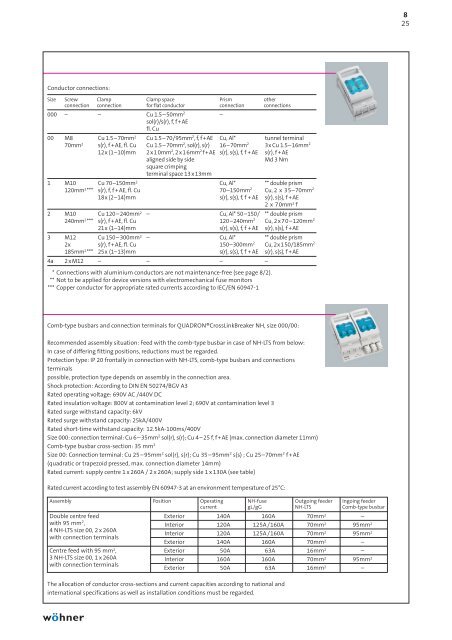
Conductor connections:<br />
old page 9/27<br />
Size Screw Clamp Clamp space Prism other<br />
connection connection for flat conductor connection connections<br />
000 – – Cu 1.5–50mm2 sol(r)/s(r), f, f+AE<br />
fl. Cu<br />
–<br />
00 M8 Cu 1.5–70mm2 Cu 1.5–70/95mm2 , f, f+AE Cu, Al* tunnel terminal<br />
70mm2 s(r), f +AE, fl. Cu Cu 1.5–70mm2 , sol(r), s(r) 16–70mm2 3x Cu 1.5–16mm2 12x (1–10)mm 2x10mm2 , 2x16mm2 f+AE s(r), s(s), f, f + AE s(r), f +AE<br />
aligned side by side<br />
square crimping<br />
terminal space 13 x 13mm<br />
Md 3 Nm<br />
1 M10 Cu 70–150mm2 Cu, Al* ** double prism<br />
120mm2 *** s(r), f, f +AE, fl. Cu 70–150mm 2 Cu, 2 x 35–70mm2 18x (2–14)mm s(r), s(s), f, f + AE s(r), s(s), f +AE<br />
2 x 70mm2f 2 M10 Cu 120–240mm2 – Cu, Al* 50–150/ ** double prism<br />
240mm2 *** s(r), f +AE, fl. Cu 120–240mm2 Cu, 2x70–120mm2 21x (1–14)mm s(r), s(s), f, f + AE s(r), s(s), f +AE<br />
3 M12 Cu 150–300mm2 – Cu, Al* ** double prism<br />
2x s(r), f +AE, fl. Cu 150–300mm2 Cu, 2x150/185mm2 185mm2 *** 25x (1–13)mm s(r), s(s), f, f + AE s(r), s(s), f +AE<br />
4a 2xM12 – – – –<br />
* Connections with aluminium conductors are not maintenance-free (see page 8/2).<br />
** Not to be applied for device versions with electromechanical fuse monitors<br />
*** Copper conductor for appropriate rated currents according to IEC/EN 60947-1<br />
Comb-type busbars and connection terminals for QUADRON®CrossLinkBreaker NH, size 000/00:<br />
Recommended assembly situation: Feed with the comb-type busbar in case of NH-LTS from below:<br />
In case of differing fitting positions, reductions must be regarded.<br />
Protection type: IP 20 frontally in connection with NH-LTS, comb-type busbars and connections<br />
terminals<br />
possible, protection type depends on assembly in the connection area.<br />
Shock protection: According to DIN EN 50274/BGV A3<br />
Rated operating voltage: 690V AC /440V DC<br />
Rated insulation voltage: 800V at contamination level 2; 690V at contamination level 3<br />
Rated surge withstand capacity: 6kV<br />
Rated surge withstand capacity: 25kA/400V<br />
Rated short-time withstand capacity: 12.5kA-100ms/400V<br />
Size 000: connection terminal: Cu 6–35mm 2 sol(r), s(r); Cu 4–25 f, f+AE (max. connection diameter 11mm)<br />
Comb-type busbar cross-section: 35 mm 2<br />
Size 00: Connection terminal: Cu 25 – 95mm 2 sol(r), s(r); Cu 35 – 95mm 2 s(s) ; Cu 25–70mm 2 f+AE<br />
(quadratic or trapezoid pressed, max. connection diameter 14mm)<br />
Rated current: supply centre 1 x 260A / 2 x 260A; supply side 1 x 130A (see table)<br />
Rated current according to test assembly EN 60947-3 at an environment temperature of 25°C:<br />
Assembly Position Operating NH-fuse Outgoing feeder Ingoing feeder<br />
current gL/gG NH-LTS Comb-type busbar<br />
Double centre feed Exterior 140A 160A 70mm2 –<br />
with 95 mm2 , Interior 120A 125A /160A 70mm2 95mm2 4 NH-LTS size 00, 2 x 260A<br />
Interior 120A 125A /160A 70mm2 95mm2 with connection terminals<br />
Exterior 140A 160A 70mm2 –<br />
Centre feed with 95 mm2 , Exterior 50A 63A 16mm2 –<br />
3 NH-LTS size 00, 1 x 260A Interior 160A 160A 70mm2 95mm2 with connection terminals<br />
Exterior 50A 63A 16mm2 –<br />
The allocation of conductor cross-sections and current capacities according to national and<br />
international specifications as well as installation conditions must be regarded.<br />
8<br />
25


![phb2013_complete_en.pdf [18.3 MB] - Wöhner](https://img.yumpu.com/12655320/1/184x260/phb2013-complete-enpdf-183-mb-wahner.jpg?quality=85)

![phb2013_08_en.pdf [1.25 MB] - Wöhner](https://img.yumpu.com/12655318/1/184x260/phb2013-08-enpdf-125-mb-wahner.jpg?quality=85)


![phb2013_deu_05.pdf [4.32 MB] - Wöhner](https://img.yumpu.com/12655312/1/184x260/phb2013-deu-05pdf-432-mb-wahner.jpg?quality=85)