

Product manual 2009English - Wöhner
Product manual 2009English - Wöhner
Product manual 2009English - Wöhner

You also want an ePaper? Increase the reach of your titles
YUMPU automatically turns print PDFs into web optimized ePapers that Google loves.
old page 9/31<br />
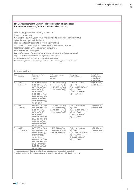
SECUR®LeanStreamer, NH in-line fuse switch disconnector<br />
for fuses IEC 60269-2 / DIN VDE 0636-2 size 1 – 2 – 3<br />
DIN VDE 0660 part 107/ EN 60947-3/ IEC 60947-3<br />
1- and 3-pole switching<br />
Mounting on a 185mm system power by screwing onto drilled busbars by screws M12<br />
Optional mounting on undrilled busbars<br />
Cable connections at top or bottom by turning switch base<br />
Shock protection with integrated positive action closure and arc chambers,<br />
has shock protection with lid open and in park position<br />
Fuses retained mechanically in lid<br />
Degree of protection (front side) IP 20 (1 pole switching) or IP 30 (3 pole switching),<br />
degree of protection near terminal depends on installation<br />
Test apertures in lid’s self-closing terminal compartment<br />
Connection space cover for shock protection and maintaining air and crawl areas<br />
Conductor terminals:<br />
Size Screw Direct connection V-direct connection Clamp resp. Clamp/prism<br />
terminal terminals terminals prism connection clamping space<br />
Cu and Al* Cu and Al* for flat copper<br />
conductor Cu<br />
1 M10 1 x 35–150mm2 s(s) 1 x 70–240mm2 s(s) Cu 1 x 120–240mm2 21x(1–12)mm/<br />
120mm2 ** 1 x 50–185mm2 sol(s) 1 x 95–300mm2 sol(s) s(r), f + AE 21x(10–21)mm<br />
1 x 35–70mm2 s(r) 1 x 50–185mm2 s(r) Cu, Al* 1 x 120–240mm2 1 x 50mm2 sol(r) 1 x 70–240mm2 sol(r) s(r), s(s), f, f + AE<br />
Md 32–40Nm Cu 2 x 120–185mm2 2 x 35–150mm2 s(s)<br />
2 x 50–185mm<br />
s(r), s(s), f, f + AE<br />
2 sol(s)<br />
2 x 35–70mm2 s(r)<br />
2 x 35–50mm2 sol(r)<br />
Md 18–24Nm<br />
2 M10 1 x 35–150mm2 s(s) 1 x 70–240mm2 s(s) Cu 1 x 120–240mm2 21x(1–12)mm/<br />
240mm2 ** 1 x 50–185mm2 sol(s) 1 x 95–300mm2 sol(s) s(r), f + AE 21x(10–21)mm<br />
1 x 35–70mm2 s(r) 1 x 50–185mm2 s(r) Cu, Al* 1 x 120–240mm2 1 x 50mm2 sol(r) 1 x 70–240mm2 sol(r) s(r), s(s), f, f + AE<br />
Md 32–40Nm Cu 2 x 120–185mm2 2 x 35–150mm2 s(s)<br />
1 x 50–185mm<br />
s(r), s(s), f, f + AE<br />
2 sol(s)<br />
2 x 35–70mm2 s(r)<br />
2 x 35–50mm2 sol(r)<br />
Md 18–24Nm<br />
3 M12 1 x 35–150mm2 s(s) 1x 120–240mm2 s(s) Cu 1 x 120–240mm2 21x(1–12)mm/<br />
2 x 185mm2 ** 1 x 50–185mm2 sol(s) 1x 150–300mm2 sol(s) s(r), f + AE 21x(10–21)mm<br />
1 x 35–70 mm2 s(r) 1x 120–300mm2 s(r) Cu, Al* 1 x 120–240mm2 1 x 50mm2 sol(r) s(r), s(s), f, f + AE<br />
Md 32–40Nm Cu 2 x 120–185mm2 2 x 35–150mm2 s(s)<br />
1 x 50–185mm<br />
s(r), s(s), f, f + AE<br />
2 sol(s)<br />
2 x 35–70mm2 s(r)<br />
2 x 35–50mm2 sol(r)<br />
Md 18–24Nm<br />
* not maintenance-free when aluminium conductors are used (see page 8/2)<br />
** copper conductor for associated rated currents in compliance with IEC/EN 60947-1<br />
Technical specifications 8<br />
30


![phb2013_complete_en.pdf [18.3 MB] - Wöhner](https://img.yumpu.com/12655320/1/184x260/phb2013-complete-enpdf-183-mb-wahner.jpg?quality=85)

![phb2013_08_en.pdf [1.25 MB] - Wöhner](https://img.yumpu.com/12655318/1/184x260/phb2013-08-enpdf-125-mb-wahner.jpg?quality=85)


![phb2013_deu_05.pdf [4.32 MB] - Wöhner](https://img.yumpu.com/12655312/1/184x260/phb2013-deu-05pdf-432-mb-wahner.jpg?quality=85)