TWSF 310 CI - Fte maximal
TWSF 310 CI - Fte maximal
TWSF 310 CI - Fte maximal

You also want an ePaper? Increase the reach of your titles
YUMPU automatically turns print PDFs into web optimized ePapers that Google loves.
User’s manual · <strong>TWSF</strong> <strong>310</strong> <strong>CI</strong><br />
The <strong>TWSF</strong> <strong>310</strong> <strong>CI</strong> will be provided with a double DVB-T output that will allow distributing the channels<br />
of the tuned transponders in two consecutive multiplex.<br />
In order to configure the device we will have two selectable modules.<br />
The options of configuration are independent. With the following exceptions:<br />
- The output channel of the second module will be set automatically as the consecutive channel<br />
after the one configured in the first module.<br />
- The output level of the multiplex will be set by the output level configured in the first module.<br />
1.3. Description and connections<br />
The module <strong>TWSF</strong> <strong>310</strong> <strong>CI</strong> is used for the reception of free channels that obey the DVB-S/DVB-S2 standards. Each<br />
module allows the reception of two complete transponders in DVB-S (QPSK) / DVB-S2 (QPSK/8PSK), and the<br />
subsequent modulation in DVB-T (COFDM) of them.<br />
A feature of this equipment is its modulator in Vestigial Side Band (or VSB). This modulation can be used to distribute<br />
adjacent channels in one distribution without any intermodulation problem.<br />
Each module has one Loop connector to cascade several modules at input and a Mix connector to do same in output<br />
channels.The output channel is selectable between C2 and C69.<br />
All parameters are programmed by the means of PRO 201 or the EVO or MINI series of field strength meter, and they are<br />
monitored in the display of programmer or in the TFT screen of field strength meter.<br />
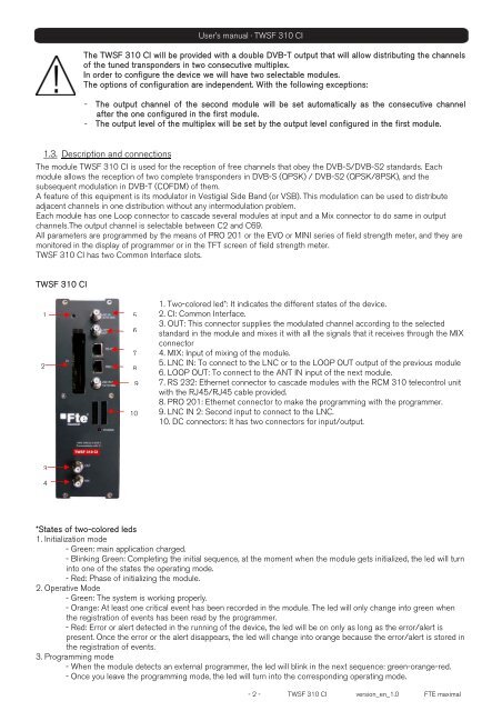
<strong>TWSF</strong> <strong>310</strong> <strong>CI</strong> has two Common Interface slots.<br />
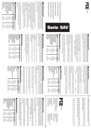
<strong>TWSF</strong> <strong>310</strong> <strong>CI</strong><br />
1<br />
2<br />
3<br />
4<br />
5<br />
6<br />
7<br />
8<br />
9<br />
10<br />
1. Two-colored led*: It indicates the different states of the device.<br />
2. <strong>CI</strong>: Common Interface.<br />
3. OUT: This connector supplies the modulated channel according to the selected<br />
standard in the module and mixes it with all the signals that it receives through the MIX<br />
connector<br />
4. MIX: Input of mixing of the module.<br />
5. LNC IN: To connect to the LNC or to the LOOP OUT output of the previous module<br />
6. LOOP OUT: To connect to the ANT IN input of the next module.<br />
7. RS 232: Ethernet connector to cascade modules with the RCM <strong>310</strong> telecontrol unit<br />
with the RJ45/RJ45 cable provided.<br />
8. PRO 201: Ethernet connector to make the programming with the programmer.<br />
9. LNC IN 2: Second input to connect to the LNC.<br />
10. DC connectors: It has two connectors for input/output.<br />
*States of two-colored leds<br />
1. Initialization mode<br />
- Green: main application charged.<br />
- Blinking Green: Completing the initial sequence, at the moment when the module gets initialized, the led will turn<br />
into one of the states the operating mode.<br />
- Red: Phase of initializing the module.<br />
2. Operative Mode<br />
- Green: The system is working properly.<br />
- Orange: At least one critical event has been recorded in the module. The led will only change into green when<br />
the registration of events has been read by the programmer.<br />
- Red: Error or alert detected in the running of the device, the led will be on only as long as the error/alert is<br />
present. Once the error or the alert disappears, the led will change into orange because the error/alert is stored in<br />
the registration of events.<br />
3. Programming mode<br />
- When the module detects an external programmer, the led will blink in the next sequence: green-orange-red.<br />
- Once you leave the programming mode, the led will turn into the corresponding operating mode.<br />
- 2 - <strong>TWSF</strong> <strong>310</strong> <strong>CI</strong> version_en_1.0 FTE <strong>maximal</strong>