Spatial Characterization Of Two-Photon States - GAP-Optique
Spatial Characterization Of Two-Photon States - GAP-Optique
Spatial Characterization Of Two-Photon States - GAP-Optique
You also want an ePaper? Increase the reach of your titles
YUMPU automatically turns print PDFs into web optimized ePapers that Google loves.
4. OAM transfer in noncollinear configurations<br />
4.1 Ellipticity in noncollinear configurations<br />
In the experimental implementation of spdc, the detection system selects the<br />
photons that are emitted in a certain spatial direction. In a collinear configuration,<br />
the selection is not a problem since all the photons are emitted in the<br />
same direction. But, in a noncollinear configuration, the photons are emitted in<br />
different azimuthal directions described by the angle α, therefore the detection<br />
system selects only a section of the full cone. As the symmetry is broken when<br />
only a portion of the cone is considered, the oam transfer mechanism can not<br />
be described by the selection rule in 3.18. This section studies this mechanism<br />
in a simple spdc configuration by calculating the spatial distribution of the<br />
signal photon after fixing the oam content of the pump and idler photons.<br />
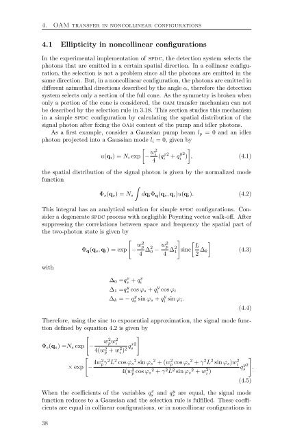
As a first example, consider a Gaussian pump beam lp = 0 and an idler<br />
photon projected into a Gaussian mode li = 0, given by<br />
<br />
u(qi) = Ni exp − w2 i<br />
4 (qx2 i + q y2<br />
i )<br />
<br />
, (4.1)<br />
the spatial distribution of the signal photon is given by the normalized mode<br />
function<br />
<br />
Φs(qs) = Ns dqiΦq(qs, qi)u(qi). (4.2)<br />
This integral has an analytical solution for simple spdc configurations. Consider<br />
a degenerate spdc process with negligible Poynting vector walk-off. After<br />
suppressing the correlations between space and frequency the spatial part of<br />
the two-photon state is given by<br />
<br />
<br />
with<br />
Φq(qs, qi) = exp<br />
− w2 p<br />
4 ∆2 0 − w2 p<br />
4 ∆2 1<br />
∆0 =q x s + q x i<br />
∆1 =q y s cos ϕs + q y<br />
i cos ϕi<br />
∆k = − q y s sin ϕs + q y<br />
i<br />
sin ϕi.<br />
<br />
L<br />
sinc<br />
2 ∆k<br />
<br />
(4.3)<br />
(4.4)<br />
Therefore, using the sinc to exponential approximation, the signal mode function<br />
defined by equation 4.2 is given by<br />
<br />
<br />
Φs(qs) =Ns exp<br />
× exp<br />
<br />
−<br />
w2 pw2 i<br />
4(w2 p + w2 qx2 s<br />
i )2<br />
− 4w2 pγ 2 L 2 cos ϕs 2 sin ϕs 2 + (w 2 p cos ϕs 2 + γ 2 L 2 sin ϕs)w 2 i<br />
4(w 2 p cos ϕs 2 + γ 2 L 2 sin ϕs 2 + w 2 i )<br />
q y2<br />
s<br />
<br />
(4.5)<br />
When the coefficients of the variables q x s and q y s are equal, the signal mode<br />
function reduces to a Gaussian and the selection rule is fulfilled. These coefficients<br />
are equal in collinear configurations, or in noncollinear configurations in<br />
38<br />
.


