TERMORETT TRV 300 1-10-5 - TA Hydronics
TERMORETT TRV 300 1-10-5 - TA Hydronics
TERMORETT TRV 300 1-10-5 - TA Hydronics

Create successful ePaper yourself
Turn your PDF publications into a flip-book with our unique Google optimized e-Paper software.
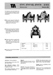
Function<br />
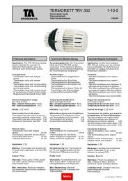
<strong>TRV</strong> <strong>300</strong><br />
When the ambient temperature rises above the set value of the thermostat, the fluid in the sensor expands and starts to close the<br />
valve.<br />
When the ambient temperature falls below the thermostat‘s set value, the fluid in the sensor contracts and the return spring in the<br />
valve starts to open the valve. When set to the frost protection position (*), the valve opens at a temperature of about 6°C in order<br />
to prevent the heating system from freezing.<br />
NB:<br />
If the <strong>TRV</strong> <strong>300</strong> with integral sensor is fitted vertically to a valve, with the sensor upwards, it may be affected by the heat from the<br />
pipe below and therefore close too early.<br />
In such cases, a thermostatic unit with a remote sensor should be used, with the sensor placed immediately beneath the radiator<br />
if possible or, if not, in the centre of the room.<br />
The scale on the thermostat represents a temperature change of 4°C between each numeral. Each mark on the scale represents<br />
a 1°C change.<br />
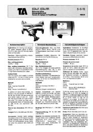
Thermostatic head with remote sensor for pocket tube or heat transfer cradle<br />
When the water temperature rises above the thermostat’s set value, the thermostat start to close the valve.<br />
When the water temperature falls below the set value, the return spring in the valve start to open the valve.<br />
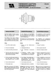
Maximum temperature restriction<br />
Set the index opposite to the maximum room temperature required. E.g. number 3 corresponding to 20°C room temperature.<br />
1. Put the restriction pin in a little way opposite to number 5 to mark the correct pin position. Close the thermostat a little by turning<br />
it clockwise.<br />
2. Fully insert the restriction pin.<br />
3. Open the thermostat by turning it anti-clockwise and check that the index stops at a position corresponding to desired room<br />
temperature.<br />
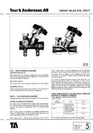
Nominal temperature range<br />
The specified temperatures apply at the nominal lift height in accordance with CEN. Under normal operating conditions, the set<br />
temperature will be maintained with a maximum deviation of ±1K.<br />
Setting scales<br />
The closing temperature is normally 2K higher than ambient temperature.<br />
Thermostatic head with integral sensor / remote sensor<br />
The various settings give approximately the following room temperatures:<br />
Thermostatic head, protective model<br />
The various settings give approximately the following room temperatures:<br />
Thermostatic head with remote setting / remote setting and remote sensor<br />
The various settings give approximately the following room temperatures:<br />
Thermostatic head with remote sensor for pocket tube or heat transfer cradle<br />
The settings produce approximately the water temperatures shown on the thermostatic head.<br />
1-<strong>10</strong>-5 - 6