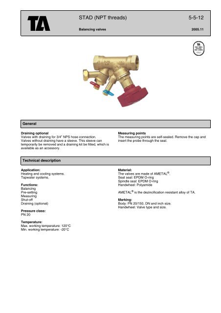
5-5-12 GB STAD NPT.fm - TA Hydronics
5-5-12 GB STAD NPT.fm - TA Hydronics
5-5-12 GB STAD NPT.fm - TA Hydronics

Create successful ePaper yourself
Turn your PDF publications into a flip-book with our unique Google optimized e-Paper software.
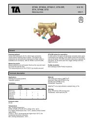
General<br />
Draining optional<br />
Valves with draining for 3/4” NPS hose connection.<br />
Valves without draining have a sleeve. This sleeve can<br />
temporarily be removed and a draining kit be fitted, which is<br />
available as an accessory.<br />
Technical description<br />
Application:<br />
Heating and cooling systems.<br />
Tapwater systems.<br />
Functions:<br />
Balancing<br />
Pre-setting<br />
Measuring<br />
Shut-off<br />
Draining (optional)<br />
Pressure class:<br />
PN 20<br />
Temperature:<br />
Max. working temperature: <strong>12</strong>0°C<br />
Min. working temperature: -20°C<br />
<strong>S<strong>TA</strong>D</strong> (<strong>NPT</strong> threads) 5-5-<strong>12</strong><br />
Balancing valves 2005.11<br />
Measuring points<br />
The measuring points are self-sealed. Remove the cap and<br />
insert the probe through the seal.<br />
Material:<br />
The valves are made of AME<strong>TA</strong>L ® .<br />
Seat seal: EPDM O-ring<br />
Spindle seal: EPDM O-ring<br />
Handwheel: Polyamide<br />
AME<strong>TA</strong>L ® is the dezincification resistant alloy of <strong>TA</strong>.<br />
Marking:<br />
Body: PN 20/150, DN and inch size.<br />
Handwheel: Valve type and size.
<strong>S<strong>TA</strong>D</strong>: <strong>NPT</strong> threads<br />
With draining<br />
d<br />
Excl. draining<br />
Excl. draining<br />
= Flow direction<br />
Draining can be installed during operation.<br />
Kvs = m 3 /h at a pressure drop of 1 bar and fully open valve.<br />
<strong>S<strong>TA</strong>D</strong>: <strong>NPT</strong> threads with union end<br />
L<br />
L<br />
L<br />
D<br />
D<br />
D<br />
= Flow direction<br />
H<br />
H<br />
H<br />
<strong>TA</strong> No<br />
d=3/4” NPS<br />
DN (Size) D L H Kvs<br />
52 151-814 15/14 1/2” N 1/2 <strong>NPT</strong> 90 100 2.52<br />
52 151-820 20 3/4” 3/4 <strong>NPT</strong> 97 100 5.70<br />
52 151-825 25 1” 1 <strong>NPT</strong> 110 105 8.70<br />
52 151-832 32 1 1/4” 1 1/4 <strong>NPT</strong> <strong>12</strong>4 110 14.2<br />
52 151-840 40 1 1/2” 1 1/2 <strong>NPT</strong> 130 <strong>12</strong>0 19.2<br />
52 151-850 50 2” 2 <strong>NPT</strong> 155 <strong>12</strong>0 33.0<br />
<strong>TA</strong> No DN (Size) D L H Kvs<br />
52 151-514 15/14 1/2” N 1/2 <strong>NPT</strong> 90 100 2.52<br />
52 151-520 20 3/4” 3/4 <strong>NPT</strong> 97 100 5.70<br />
52 151-525 25 1” 1 <strong>NPT</strong> 110 105 8.70<br />
52 151-532 32 1 1/4” 1 1/4 <strong>NPT</strong> <strong>12</strong>4 110 14.2<br />
52 151-540 40 1 1/2” 1 1/2 <strong>NPT</strong> 130 <strong>12</strong>0 19.2<br />
52 151-550 50 2” 2 <strong>NPT</strong> 155 <strong>12</strong>0 33.0<br />
<strong>TA</strong> No DN (Size) D L H Kvs<br />
52 167-414 15/14 1/2” N 1/2 <strong>NPT</strong> <strong>12</strong>2 100 2.52<br />
52 167-420 20 3/4” 3/4 <strong>NPT</strong> 132 100 5.70<br />
52 167-425 25 1” 1 <strong>NPT</strong> 153 105 8.70<br />
Draining can be installed during operation.<br />
Kvs = m 3 /h at a pressure drop of 1 bar and fully open valve.<br />
5-5-<strong>12</strong> - 2
Setting<br />
Setting of a valve for a particular pressure drop, e g corresponding to 2.3 turns on the graph, is carried out as follows:<br />
1. Close the valve fully (Fig 1).<br />
2. Open the valve 2.3 turns (Fig. 2).<br />
3. Using a 3 mm Allen key, turn the inner spindle clockwise until stop.<br />
4. The valve is set.<br />
To check the setting: Close the valve, the indicator shows 0.0. Open it to the stop position. The indicator then shows the set value,<br />
in this case 2.3 (Fig. 2).<br />
Diagrams showing the pressure drop for each valve size at different settings and flow rates are available to help determine the<br />
correct valve size and pre-setting (pressure drop). Four turns corresponds to fully opened valve (see Fig. 3). Opening it further will<br />
not increase the capacity.<br />
Fig. 1. Fig. 2. Fig. 3.<br />
Valve closed The valve is set at 2.3 Fully open valve<br />
Measuring accuracy<br />
The zero position is calibrated and must not be changed.<br />
Deviation of flow at different settings<br />
The curve (Fig. 4) is valid for valves with normal pipe fittings* (Fig. 5). Try also to avoid mounting taps and pumps, immediately<br />
before the valve.<br />
Fig 4<br />
Fig 5<br />
Setting, No. of turns.<br />
*) The valve can be installed with the opposite flow direction. The specified flow details also are valid for this direction although<br />
tolerances can be greater (maximum 5% more).<br />
Correction factors<br />
The flow calculations are valid for water (+20°C). For other liquids with approx. the same viscosity as water (≤20 cSt = 3°E =<br />
100 S.U.), it is only necessary to compensate for the specific density. However, at low temperatures, the viscosity increases and<br />
laminar flow may occur in the valves. This causes a flow deviation that increases with small valves, low settings and low differential<br />
pressures. Correction for this deviation can be made with the software <strong>TA</strong> Select or direct in <strong>TA</strong>-CBI.<br />
5-5-<strong>12</strong> - 3
Sizing<br />
When ∆p and the design flow are known, use the formula to calculate the Kv-value or use the diagram.<br />
Support material<br />
Software<br />
<strong>TA</strong> Select: Makes it easy to choose the right balancing valves by taking into account the desired flow, pressure drop and flow rate.<br />
Measuring instruments<br />
Use the balancing instrument <strong>TA</strong>-CBI. It is programmed with valve characteristics for <strong>TA</strong> valves, enabling measured differential<br />
pressure to be read off directly as a flow rate. For further information on <strong>TA</strong>-CBI, see catalogue leaflet <strong>TA</strong>-CBI.<br />
Conversion disc<br />
By using the conversion disc it is easy to calculate the relationship between flow, pressure and setting values for all valve sizes.<br />
Manuals<br />
See the following manuals for descriptions of various balancing methods:<br />
Total hydronic balancing<br />
Manual no. 1: Balancing control circuits<br />
Manual no. 2: Balancing distribution systems<br />
Manual no. 3: Balancing of radiator systems<br />
Manual no. 4: Hydronic balancing with differential pressure controllers<br />
Kv values<br />
<strong>S<strong>TA</strong>D</strong><br />
No of<br />
turns DN 15/14 DN 20 DN 25 DN 32 DN 40 DN 50<br />
0.5 0.<strong>12</strong>7 0.511 0.60 1.14 1.75 2.56<br />
1 0.2<strong>12</strong> 0.757 1.03 1.90 3.30 4.20<br />
1.5 0.314 1.19 2.10 3.10 4.60 7.20<br />
2 0.571 1.90 3.62 4.66 6.10 11.7<br />
2.5 0.877 2.80 5.30 7.10 8.80 16.2<br />
3 1.38 3.87 6.90 9.50 <strong>12</strong>.6 21.5<br />
3.5 1.98 4.75 8.00 11.8 16.0 26.5<br />
4 2.52 5.70 8.70 14.2 19.2 33.0<br />
Example<br />
Wanted:<br />
Presetting for DN 25 at a desired flow rate of 1,6 m 3 /h and a pressure drop of 10 kPa.<br />
Solution:<br />
Draw a straight line joining 1,6 m 3 /h and 10 kPa. This gives Kv=5. Now draw a horizontal line from Kv=5.<br />
This intersects the bar for DN 25 which gives 2,35 turns.<br />
NOTE:<br />
If the flow rate is out of the scale in the diagram, the reading can be made as follows:<br />
Starting with the example above, we get 10 kPa, Kv=5 and flow-rate 1.6 m 3 /h.<br />
At 10 kPa and Kv=0,5 we get the flow-rate 0,16 m 3 /h, and at Kv=50, we get 16 m 3 /h. That is, for a given pressure drop, it is possible<br />
to read 10 times or 0.1 times the flow and Kv-values.<br />
5-5-<strong>12</strong> - 4
Diagram<br />
*) Recommended area<br />
**) 25 db (A)<br />
***) 35 db (A)<br />
*<br />
*<br />
*<br />
*<br />
5-5-<strong>12</strong> - 5<br />
*<br />
*<br />
*<br />
*<br />
*<br />
*<br />
*<br />
*<br />
***<br />
**
Accessories<br />
Measuring point<br />
Max <strong>12</strong>0°C<br />
Measuring point, extension 60 mm<br />
Can be installed without draining of the system.<br />
Draining kit<br />
Can be installed during operation<br />
d<br />
Handwheel, complete<br />
Size plate, handwheel<br />
Identification tag<br />
(incl 1 pc per valve)<br />
Allen key<br />
1 1/4<br />
<strong>TA</strong> No L<br />
52 179-014 44<br />
52 179-015 103<br />
<strong>TA</strong> No<br />
52 179-006<br />
<strong>TA</strong> No d<br />
52 179-997 3/4” NPS<br />
<strong>TA</strong> No<br />
52 186-003<br />
<strong>TA</strong> No Size<br />
308 8<strong>12</strong>-01 1/2N<br />
308 8<strong>12</strong>-02 3/4<br />
308 8<strong>12</strong>-03 1<br />
308 8<strong>12</strong>-04 1 1/4<br />
308 8<strong>12</strong>-05 1 1/2<br />
308 8<strong>12</strong>-06 2<br />
<strong>TA</strong> No<br />
52 161-990<br />
<strong>TA</strong> No<br />
52 187-103 3 mm Pre-setting<br />
52 187-105 5 mm Draining<br />
Tour & Andersson retains the right to make changes to its products and specifications without prior notice.<br />
5-5-<strong>12</strong> - 6