En bitube: Cône pour cle Allen 2,5 mm, Die ... - TA Hydronics
En bitube: Cône pour cle Allen 2,5 mm, Die ... - TA Hydronics
En bitube: Cône pour cle Allen 2,5 mm, Die ... - TA Hydronics

You also want an ePaper? Increase the reach of your titles
YUMPU automatically turns print PDFs into web optimized ePapers that Google loves.
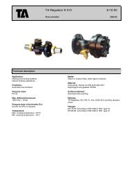
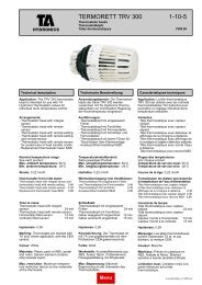
Applications:<br />
Heating installations, single or two pipe<br />
systems - pumped circulation.<br />
Anwendungsbereich:<br />
Pumpenwarm- wasserheizung 1 - oder<br />
2-Rohrsysteme.<br />
Max static pressure: 1.0 MPa = 10 bar. Max Betriebsdruck: 1,O MPa = 10 bar.<br />
Max differential pressure: The maxi-<br />
mum reco<strong>mm</strong>ended pressure drop to<br />
avoid noise is 5 mWG = 50 kPa = 0.5<br />
bar. (All valves and sizes).<br />
Max. Differenzdruck: Max. empfohle-<br />
ner Differenzabfall zur Gerauschver-<br />
meidung: 5 mWS = 50 kPa = 0,5 bar.<br />
(Gilt fur samtliche Ventile und Dimen-<br />
sionen).<br />
Applications:<br />
Installations de chauffage monotube ou<br />
<strong>bitube</strong> avec circulateur.<br />
Pression statique maxi: 1,O MPa = 10 bar<br />
Pression differentielle maxi: La perte<br />
de charge maximale reco<strong>mm</strong>andee<br />
<strong>pour</strong> eviter le bruit est de 5 mCE = 50<br />
KPa = 0,5 bar. (Valable <strong>pour</strong> tous les ro-<br />
binets et toutes les dimensions).<br />
Max working temperature: 120 "C Max Betriebstemperatur: 120 "C. Temperature de service maxi: 120 "C<br />
Material: Valve and diverter: die cast<br />
AME<strong>TA</strong>L@ or hot-forged brass.<br />
Hand controlled valves: Handwheel -<br />
acetal plastic. Spindle seal- o-ring which<br />
can be replaced, if necessary, without<br />
having to draining the system.<br />
Thermostatically controlled valves: See<br />
RVTsheet .<br />
Connecting pipe: Nickel-plated steel.<br />
Flexible connector: A special fitting has<br />
been developed for connection to off<br />
centre pipework.<br />
Return shut-off: The diverters have a<br />
built-in isolation which enables the<br />
radiator to be removed without having to<br />
drain the system.<br />
Pre-setting, single-pipe manifold: The<br />
% flow to the radiator can be varied by<br />
re-setting the cone (see diagram).<br />
Pre-setting two-pipe manifold: Preset-<br />
ting is carried out at the valve (see dia-<br />
gram).<br />
Marking: The diverters are marked with<br />
<strong>TA</strong>, as well as arrows indicating flow and<br />
return connections. The Cap is <strong>cle</strong>arly<br />
marked with 1 or 2 to indicate whether it<br />
is set for single or two-pipe application.<br />
Material: Ventil und Verteiler: Spritz-<br />
gu B-AME<strong>TA</strong>LB oder warm gepre Btes<br />
Messing.<br />
Ventile mit Handbetatigung:<br />
Handrad: Acetal-Kunststoff. Spindeldich-<br />
tung: o-Ring (kann bei Bedarf ohne Anla-<br />
genent- leerung ausgetauscht werden).<br />
Thermostatventile: Siehe RVT Typen-<br />
blatt.<br />
Verbindungsrohr: Stahl, verzinkt und<br />
glanzchromatisiert.<br />
Sockelmontage: Spezieller Nippel fur<br />
flexiblen RohranschluB im Sockel.<br />
Rucklaufabsperrung: <strong>Die</strong> Verteiler ha-<br />
ben eine eingebaute Rucklaufabsper-<br />
rung, so da8 der Heizkörper ohne Anla-<br />
genentleerung ausgebaut werden kann.<br />
Voreinstellung fur l -Rohr-AnschluB: Im<br />
Verteiler gibt es einen Kegel, der fur un-<br />
terschiedliche %-Durchflusse zum Heiz-<br />
körper eingestellt werden kann. Siehe<br />
auch das Diagra<strong>mm</strong>.<br />
Voreinstellung fur 2-Rohr-AnschluB:<br />
<strong>Die</strong> Voreinstellung erfolgt am Ventil-<br />
teil: Siehe auch das Diagra<strong>mm</strong>.<br />
Kennzeichnung: <strong>Die</strong> Verteiler sind auf<br />
dem Ventilgehause mit <strong>TA</strong> sowie einge-<br />
gossenen Pfeilen gekennzeichnet, wel-<br />
che die DurchfluBverbindungen ange-<br />
ben. <strong>Die</strong> <strong>En</strong>dkappe ist je nach Liefe-<br />
reinstellung mit Einrohr oder Zweirohr<br />
gekennzeichnet.<br />
Surface treatment: Nickel-plated. Ooberflachenbehandlung: Vernickelt<br />
Materiaux: Robinet et distributeur:<br />
AME<strong>TA</strong>L@ coule sous pression ou laiton<br />
estampe.<br />
Robinets manuels: Poignee : Plastique<br />
Acetal. Etancheite de tige: Joint torique<br />
pouvant etre remplace sans avoir a vi-<br />
danger I'installation.<br />
Robinets thermostatiques: Voir la feuille<br />
des specifications techniques des robi-<br />
nets RVT.<br />
Tube de liaison: Acier nickele brillant.<br />
Montage en plinthe: Ce montage est<br />
possible a I'aide des raccords excentri-<br />
ques mobiles <strong>TA</strong>.<br />
Arret sur le retour: Un dispositif d'isole-<br />
ment dans le distributeur permet la de-<br />
pose du radiateur sans avoir a vidanger<br />
I'installation.<br />
Prereglage:<br />
<strong>En</strong> monotube: <strong>Cône</strong> <strong>pour</strong> <strong>cle</strong> <strong>Allen</strong> 2,5<br />
<strong>mm</strong>, devisse. La tige <strong>pour</strong> <strong>cle</strong> <strong>Allen</strong> 4 <strong>mm</strong><br />
permet de regler le <strong>pour</strong>centage du de-<br />
bit vers le radiateur en fermant f le re-<br />
tour de celui-ci. (Voir abaque).<br />
<strong>En</strong> <strong>bitube</strong>: <strong>Cône</strong> <strong>pour</strong> <strong>cle</strong> <strong>Allen</strong> 2,5 <strong>mm</strong>,<br />
vissee a fond. Le prereglage s'effectue<br />
sur le robinet en partie superieure. (Voir<br />
abaque) .<br />
Marquage: Le sigle <strong>TA</strong> et des fleches de<br />
co<strong>mm</strong>unications figurent sur le corps du<br />
distributeur. Le chiffre 1 ou 2 sur le bou-<br />
chon indique la version du distributeur<br />
livre,l <strong>pour</strong> monotube et 2 <strong>pour</strong> <strong>bitube</strong>.<br />
Traitement de surface: Nickele.
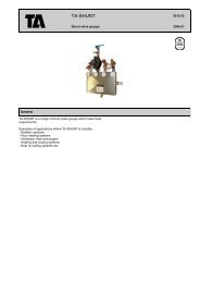
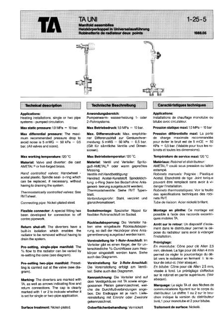
The <strong>TA</strong> Universal radiator manifold ass- <strong>Die</strong> Universalheizkörperkoppeln UNI sind L'ensemble de robinetterie de radiateur<br />
embly is a complete valve combination komplette Ventilgarnituren fur Standard- UNI peut etre monte sur la majorite des<br />
for fitting to standard radiators. heizkörper. radiateurs existants sur le marche.<br />
It consists of five main parts which can Sie bestehen aus funf Hauptteilen, die zu II comprend cinq elements principaux<br />
be combined into a complete unit for sin- einem kompletten Ventil fur l-Rohr - rendant possible son utilisation en mo-<br />
gle-pipe or two-pipe systems, with either oder 2-Rohr-Systeme, fur verschiedene notube ou en <strong>bitube</strong>, avec tte manuelle<br />
manual or thermostatic control. Connec- Heizkörperhöhen und fur manuellen ou thermostatique. Des tubes de liaison<br />
ting pipes are available to suit a variety oder Thermostatbetrieb zusa<strong>mm</strong>enge- sont disponibles en plusieurs longueurs<br />
of radiator heig hts. baut werden können. <strong>pour</strong> convenir aux differentes hauteurs<br />
des radiateurs.<br />
The main components are: <strong>Die</strong> Hauptteile sind: Ces cinq elements sont:<br />
Universal diverter adaptable for single Verteiler in Universalausfuhrung, um- Distributeur universel, utilisable en mo-<br />
pipe or two-pipe applications may be tur- stellbar fur l-Rohr - oder 2-Rohr-Ausfuh- notube ou en <strong>bitube</strong>. Raccordement<br />
ned for side or bottom connection. rung sowie wechselbar fur AnschluB von <strong>pour</strong> tubes en plinthe ou encastrés.<br />
unten oder von der Seite her.<br />
Valve unit for manual or thermostatic Ventilteil, manuell oder thermostat- Robinet de radiateur manuel ou ther-<br />
control. gesteuert. mostatique.<br />
Connenctions to suit various makes of Heizkörperanschlusse fur Heizkörper, Raccords divers <strong>pour</strong> les differents<br />
radiators. mit oder ohne Voreinstellung und in Aus- types de radiateurs et <strong>pour</strong> differents<br />
fuhrung fur den AnschluB an Standard- montages.<br />
heizkörper.<br />
Connecting pipe Nickel-~lated quality<br />
steel tubing.<br />
Verbindungsrohr Rohr aus Qualitatsstahl,<br />
verzinkt und glanzchromatiert und<br />
mit dunner Kunststoffolie beschichtet.<br />
Tube de liaison: Acier nickele brillant.<br />
Couplings FPL and FPL-PX Kupplungen Typ FPL oder FPL-PX. Raccordement aux tubes d'alimentation<br />
en cuivre ou en polyethylene reticule.<br />
Raccords FPL et FPL-PX.<br />
Specifications. The <strong>TA</strong> Universal mani- Spezifikation. <strong>Die</strong> Universalheizkörper- Specifications: La robinetterie <strong>TA</strong> UNI<br />
fold assembly can be ordered as se- koppel UNI kann in Einzelteilen oder als peut etre co<strong>mm</strong>andee par element seul<br />
parate components or as a complete komplette Einheit bestellt werden. ou par ensemble complet.<br />
assembly.<br />
12 <strong>mm</strong><br />
12 <strong>mm</strong> (Rilsan)<br />
15 <strong>mm</strong><br />
12 <strong>mm</strong><br />
12 <strong>mm</strong><br />
12 <strong>mm</strong>
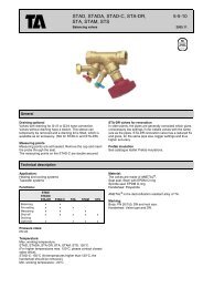
Return pipe<br />
Rucklaufrohr<br />
Canne antimonocirculation<br />
The return pipe must always be fitted in<br />
the case of a single-pipe system in order<br />
to prevent double circulation.<br />
-The nut and cone at (A) are moved to<br />
(D) if a side-connected diverter is desi-<br />
red.<br />
-The re-setting cone (B) in its screwed-in<br />
position (2,5 <strong>mm</strong> <strong>Allen</strong> key) provides a<br />
two-pipe diverter. Re-setting to single-<br />
pipe is carried out by unscrewing the<br />
cone out.<br />
- Cap marked UNI IIUNI 2 indicates deli-<br />
very setting singleltwo-pipe. (Can also<br />
be used as pressure-testing plug at (A)<br />
or (D)).<br />
- Setting cone (C) is used to shut off<br />
against radiator (4 <strong>mm</strong> <strong>Allen</strong> key.).<br />
Connection pipe Lengths = centre-centre <strong>mm</strong><br />
Verbi ndungsrohre Langen = Mitte-Mitte <strong>mm</strong><br />
Tube de liaison Longueur = entre-axe moins<br />
DN 10 = -36 <strong>mm</strong><br />
DN 15 = -106 <strong>mm</strong><br />
ACHTUNG!<br />
Bei l-Rohr-Systemen sol1 stets ein<br />
Tauchrohr installiert werden, um eine<br />
Doppelzirkulation zu verhindern.<br />
- Mutter und Konus von (A) nach (D)<br />
wechseln, wenn ein Verteiler mit seitli-<br />
chem AnschluB gewunscht wird.<br />
- Umstellkegel (B) in eingeschraubter<br />
Lage (Innensechskant 2,5 <strong>mm</strong>) ergibt<br />
2-Rohr-Verteiler. Umstellung auf l-Rohr<br />
erfolgt durch Herausschrauben des<br />
Kegels.<br />
- <strong>En</strong>dkappe mit Kennzeichnung<br />
UNI 1lUNI 2 gibt Liefereinstellung an:<br />
l-Rohrl2-Rohr. (Kann auch als Druck-<br />
prufungskappe beim (A) oder (D) ver-<br />
wendet werden) .<br />
- Einstellkegel (C) wird zum Absperren<br />
des Heizkörpers (Innensechskant 4 <strong>mm</strong>)<br />
verwendet.<br />
- In the case of a single-pipe system the -Bei l-Rohr-Einsatz dient dieser Kegel<br />
cone is also used for %-distribution to auch zur %-Einstellung des Heizkörper-<br />
radiator. durchfluBes (0-50%).<br />
REMARQUE:<br />
<strong>En</strong> monotube, toujours utiliser la canne<br />
antimonocirculation.<br />
- Cecrou et I'olive sur (A) peuvent etre<br />
places sur (D) <strong>pour</strong> obtenir un distribu-<br />
teur avec raccordement <strong>pour</strong> tubes en<br />
plinthe.<br />
- Lorsque le cône (B) <strong>pour</strong> <strong>cle</strong> <strong>Allen</strong> 2,5<br />
<strong>mm</strong> est visse a fond, le distributeur est<br />
prevu <strong>pour</strong> du <strong>bitube</strong>. II suffit de le visser<br />
<strong>pour</strong> obtenir un distri buteur monotube.<br />
- Le bouchon marque UNI IIUNI 2 indique<br />
que le distributeur est livré en version<br />
monotubel <strong>bitube</strong>. (Pour proceder aux<br />
essais sous pression, le bouchon peut<br />
etre monte sur (A) ou (D).<br />
- <strong>En</strong> monotube la tige (C) <strong>pour</strong> <strong>cle</strong> <strong>Allen</strong> 4<br />
<strong>mm</strong> peut etre utilisee <strong>pour</strong> regler le<br />
<strong>pour</strong>centage du debit vers le radiateur<br />
ou <strong>pour</strong> isoler celui-ci.
HOW TO ORDER UNI MANIFOLD ASSEMBLIES (The pipeis not included)<br />
BESTELLMUSTER FUR UNI-KOPPELN (Verbindungsrohre gehöre nicht zum Lieferumfang)<br />
MODELE DE COMMANDE POUR ENSEMBLE <strong>TA</strong>-UNI (Le tube de liaison n'est pas compris)<br />
Ex.1z:B. 50 64'7 -100 = 1 50 600-100 DN 10<br />
1 50 620-112 DN 10<br />
2 50 701-116 KRK 112<br />
<strong>TA</strong> No for Complete assembly<br />
UNI-Koppel, kpl., <strong>TA</strong> Nr<br />
No <strong>TA</strong> <strong>pour</strong> ensemble complet<br />
DIVERTERSIVERTEILERIDISTRIBUTEUR<br />
L22<br />
VALVESIVENTILOBERTEILEIROBINET<br />
Manual operation<br />
Fur manuellen Betrieb 34<br />
Manuel<br />
YJ<br />
t<br />
l<br />
1.5<br />
50 XXX-xxx<br />
UNI 1 DN 10<br />
50 600 -100<br />
UNI 1 DN 15<br />
50 600 - 300<br />
RVO DN 10<br />
50 610-112<br />
m<br />
RVO DN 15<br />
50 50 615-115<br />
For thermostat control<br />
M22x"5-r-<br />
Fur Thermostatbetrieb RVT DN 10<br />
Thermostatisable 50 620-112<br />
f-<br />
L<br />
6x1.5<br />
RVT DN 15<br />
50 625 -115<br />
CONNECTIONSIANSCHLUSSTEILEIRACCORDS POUR RADIATEURS<br />
Straight union<br />
Gerade HeizkörperanschluB X 1.5<br />
Raccord droit 50 701 -110<br />
Bent Union<br />
AnschluB bogen<br />
Raccord coude<br />
More information about radiator valves is found in leaflet<br />
Detailinformation uber Heizkörperventile können in folgende Typenblattern gefunden werden<br />
Pour de plus amples information sur les radiateurs thermostatisables voir notice<br />
RVO, RVO-F 1- 5-5<br />
RVT 1-1 0-5<br />
RVT 40 F 1-1 0-7<br />
+
<strong>TA</strong> No for complete assembly<br />
UNI-Koppel, kpl., <strong>TA</strong> Nr<br />
No <strong>TA</strong> <strong>pour</strong> ensemble complet<br />
Manual operation<br />
without presetting<br />
Fur manuellen Betrieb<br />
Manuel<br />
Manual operation and presetting<br />
Fur manuellen Betrieb und<br />
Voreinstellung f<br />
Manuel avec prereglage<br />
For thermostat control<br />
Fur Thermostatbetrieb<br />
Thermostatisable<br />
- 1.5<br />
t<br />
l<br />
50 xxx-xxx<br />
UNI 2 DN 10<br />
50 600-200<br />
UNI 2 DN 15<br />
50 600-400<br />
RVO DN 10<br />
50 610 -112<br />
RVO DN 15<br />
50 615 -115<br />
RVO-FDN 15<br />
50 616 -115<br />
RVT DN 10<br />
50 620 -112<br />
RVT DN 15<br />
50 625 -115<br />
For thermostat control M2x195-'<br />
and presetting<br />
RVT 40 F<br />
Fur Thermostatbetrieb DN 10<br />
und Voreinstellung 50 621 -112<br />
Thermostatisable avec 6x1,s<br />
prereglage<br />
RVT 40 F<br />
DN 15<br />
50 626-115<br />
CONNECTIONS/ANSCHLUSSTEILE/RACCORDS POUR RADIATEURS<br />
Straight union<br />
Gerader HeizkörperanschluB X 1.5<br />
Raccord droit<br />
-8 - 50 701 -110<br />
Bent Union<br />
AnschluB bogen<br />
Raccord coude<br />
KRK x 1.5<br />
50 701 -116<br />
1 1<br />
1<br />
1
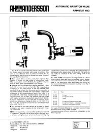
When delivered, the diverter is set for Der Verteiler ist bei Lieferung fur 50% Le distributeur est regle a la livraison<br />
50% flow to the radiator. This gives DurchfluB zum Heizkörper eingestellt. <strong>pour</strong> un débit vers le radiateur de 50%<br />
Kv = 2,O. With a flow of 130 I/h you get <strong>Die</strong>s ergibt einen Kv-Wert von 2,O. Bei ce qui donne un Kv = 2,O.<br />
Ap = 40 <strong>mm</strong>WG. einem DurchfluB von 130 I/h erhalt man Pour un debit de 130 I/h, on obtient un<br />
Ap = 0,4 kPa (40 <strong>mm</strong>WS) Ap = 40 <strong>mm</strong>CE.<br />
Pour un robinet thermostatique et <strong>pour</strong><br />
un AT 2 K, on obtient: Kv = 1,7.<br />
Thermostat-controlled valve at AT 2 K Thermostatgesteuertes Ventil bei AT 2 K On obtient egalement un Kv = 1,7 dans<br />
gives Kv = 1,7. Even with the diverter ergibt einen Kv-Wert von 1,7. Wenn der le cas d'un distributeur regle <strong>pour</strong> un de-<br />
set for flow distribution of 40% to the Verteiler fur eine DurchfluBssverteilung bit vers le radiateur de 40% (2 tours de<br />
radiator gives Kv = 1,7 (2 turns of the von 40% zum Heizkörper eingestellt ist, la tige de reglage. <strong>cle</strong> <strong>Allen</strong> 4 <strong>mm</strong>). La<br />
setting cone). Pressure drop at 130 I/h erhalt man ebenfalls einen Kv-Wert von perte de charge a 130 I/h devient dans ce<br />
will in this case be Ap = 0,6 kPa. 1,7. (2 Umdrehungen an Einstellkegel). cas Ap = 0,6 kPa.<br />
Der Druckabfall bei 130 I/h betragt in die-<br />
sem Fall Ap = 0,6 kPa (60 <strong>mm</strong>WS)<br />
The diagram shows the pressure drop in Aus dem Diagra<strong>mm</strong> geht der Druckabfall <strong>En</strong> consultant I'abaque, il est possible de<br />
the manifold at different presettings and im Kreis bei verschiedenen Voreinstel- determiner la perte de charge de I'en-<br />
with the thermostat valve unit fully open lungen und mit vol1 geöffnetem bzw. mit semble <strong>pour</strong> differentes positions de re-<br />
or with an opening corresponding to AT entsprechend AT 2 K geöffnetem Ther- glage. De meme <strong>pour</strong> le robinet ther-<br />
2 K. mostatventilteil hervor. mostatique en position totalement ou-<br />
verte ou en position ouverte correspon-<br />
dant a un AT 2 K.<br />
Thermostat control Thermostatbetrieb Reglage thermostatique<br />
Available pressure: 800 <strong>mm</strong>WG (8 kPa) Verfugba~er Druck: 8kPa(80 <strong>mm</strong>WS) Pression disponible: 800 <strong>mm</strong>CE (8 kPa)<br />
Desired flow: 20 I/ h (DN 10) Gewunschter DurchfluB: 20 I/h (DN 10) Debit souhaite: 20 I/h (DN 10)<br />
The diagram indicates Kv = 0.07, which Wie aus dem Diagra<strong>mm</strong> hervorgeht, ist II ressort de I'abaque un Kv = 0,07 cor-<br />
gives a setting of 3. Kv = 0,07, der Einstellung 3 ergibt. respondant a la position de reglage 3.<br />
Available pressure: 900 <strong>mm</strong>WG (9 kPa) Verfugbarer Druck : 9 kPa(9OO <strong>mm</strong>WS) Pression disponible: 900 <strong>mm</strong>CE (9 kPa)<br />
Desired flow: 60 I/h (DN 15) Gewunschter DurchfluB: 60 I/h (DN 15) Debit souhaite: 60 I/h (DN 15)<br />
The diagram indicates Kv = 0.2 wich Wie aus dem Diagra<strong>mm</strong> hervorgeht, ist II ressort de I'abaque un Kv = 0,2 cor-<br />
gives a setting of 4.2. Kv = 0,2, der Einstellung 4,2 ergibt. respondant a la position de reglage 4,2.<br />
Kv for different openings Kv bei unterschiedlichen Offnungen Valeurs Kv <strong>pour</strong> differents degres<br />
AT<br />
1 K<br />
2K<br />
3K<br />
Fully open<br />
RVT<br />
0,3<br />
0,6<br />
0,9<br />
1,O<br />
RVO<br />
-<br />
-<br />
-<br />
1,o<br />
AT<br />
1K<br />
2K<br />
3K<br />
Vollgeöff net<br />
RVT<br />
0,3<br />
0,6<br />
0,9<br />
1,O<br />
Kv = Valve coeff icient (m3/h at 1 bar). Kv = Ventilkoeffizient (m3/h bei 1 bar) Kv = Coeff icient de la vanne (m3/h<br />
A T = temp-difference measured a l bar)<br />
in Kelvin (1 K = 1°C)<br />
RVO<br />
-<br />
-<br />
-<br />
1,o<br />
AT<br />
RVT RVO<br />
Björsells, Borås
Thrust nut and cone FPL (copper tube)<br />
Druckmutter und Konus FPL (Kupferrohr)<br />
Ecrou et olive FPL (Tube cuivre) M22x1,S<br />
2m5[D ~hrust nut Cone D<br />
Druckmutter Konus<br />
Ecrou Olive<br />
Support bushes<br />
Stutzhulsen<br />
Douilles de renforcement<br />
CoppetubelKupferrohrITube cuivre<br />
<strong>TA</strong>.nr Size<br />
<strong>TA</strong>. Nr RohrgröBe<br />
No <strong>TA</strong> 0 ext. du tube x epasseur<br />
Thrust nut and cone FPL-PX (Plastic tube)*)<br />
Druckmutter und Konus FPL-PX (Kunststoffrohr)*)<br />
Ecrou et olive FPL-PX complet avec douille*)<br />
*) Incl. support buscheslMit StutzhulselAvec douilles de renforcement<br />
Transition socket (swivelling nut)<br />
for use with steel tube<br />
~bergangshulse (laufende Mutter)<br />
Raccord intermediaire (ecrou tournant)<br />
<strong>TA</strong> No<br />
<strong>TA</strong>. Nr<br />
No <strong>TA</strong> D L<br />
50 723-1 10 G318 22<br />
L -1 15 G112 23<br />
Elbow connection (swivelling nut) prepared<br />
for KOMBI on steel tube<br />
WinkelanschluB (laufende Mutter)vorbereitet<br />
fur KOMBI<br />
Raccord equerre (ecrou tournant)prevu <strong>pour</strong> KOMBI<br />
M22x 1.5<br />
<strong>TA</strong> No<br />
<strong>TA</strong>. Nr<br />
h-unit for joint-free piping in floor and<br />
connection to coupling<br />
h-Stuck fur verbindungsfreie Verlegung von<br />
Rohren in FuBböden und AnschluB an Kupplungen<br />
Raccord en "H" <strong>pour</strong> montage sans joint<br />
<strong>TA</strong> No<br />
Flexible socket connection<br />
Flexibler SockelanschluB<br />
Raccord excentrique mobile<br />
No <strong>TA</strong> d L H Kvs<br />
<strong>TA</strong> No<br />
<strong>TA</strong>. Nr<br />
No <strong>TA</strong><br />
Balancing key for RVT 40 F<br />
Einstellschlussel fur RVT 40 F<br />
Dispositif de prereglage <strong>pour</strong> RVT 40 F<br />
For fitting on valve with thermostat bonnet<br />
Zur Montage auf Thermostatventil<br />
Pour montage sur robinet thermostatisable<br />
Handwheel For key operation<br />
Handrad Loser Schlussel<br />
Tete manuelle Dispositif de reglage <strong>pour</strong> <strong>cle</strong> <strong>Allen</strong><br />
<strong>TA</strong> No<br />
<strong>TA</strong>. Nr<br />
No <strong>TA</strong>
RVT 50 B, RVT 50 C<br />
Thermostatic head with integral sensor<br />
Thermostatkopf mit eingebautem Fuhler<br />
=te thermostatique avec detecteur et<br />
affichage du point de consigne incorpores<br />
L ] <strong>TA</strong> No<br />
<strong>TA</strong>. Nr<br />
No <strong>TA</strong><br />
50 341-201 (RVT 50 B) 6-26 "C<br />
-301 (RVT 50 C) 0-26 "C<br />
RVT 60 B<br />
Thermostatic head with remote sensor<br />
Thermostatkopf mit Fernfuhler<br />
Tete thermostatique avec detecteur a<br />
distance et aff ichage du point de<br />
consigne incorpore<br />
More information about <strong>TA</strong> thermostat units is found in leaflet 1-10-10.<br />
Mehr Information uber <strong>TA</strong>-Thermostatoberteile, s Blatt 1-10-10.<br />
Pour de plus amples informations sur les tetes thermostatiques RVT<br />
de <strong>TA</strong> voir notice No. 1-10 -10.<br />
Next radiator<br />
Nachster Radiator<br />
Prochain radiateur<br />
RVT 90 B<br />
Remote sensor head with integral sensor<br />
and valve actuator<br />
Thermostatkopf mit Fernfuhler und Ferneinstellung<br />
-te thermostatique avec detecteur et affichage<br />
du point de consigne a distance<br />
Plug<br />
Stopfen<br />
Bouchon<br />
<strong>TA</strong>. Nr<br />
Application: Pressure-testing of feed pipe to manifold<br />
Anwendungsbereich: Druckprufung der UNI Koppel Anspeisung<br />
Application: Pour essai sous pression de la tuyauterie<br />
d'alimentation au distributeur<br />
Cap for diverter<br />
Kappe fur Verteiler<br />
Boucho<br />
Riser<br />
Strang<br />
Retour<br />
303 439-01 Single-pipell-Rohrl<br />
Monotube UNI 1<br />
303 439 -02 Two-pipel2-Rohrl<br />
Bitube UNI 2<br />
Björsells. Bor&
SINGLE-PIPEII -ROHR/MONOTUBE<br />
Kv - max = 2,O<br />
Flow % to radiator with different Kv-values<br />
DurchfluB-% zurn Heizkörper bei unterschiedlichen Kv-Werten<br />
om<br />
Pourcentage du debit vers le radiateur <strong>pour</strong> Kv valeurs differentes<br />
1 l l 1 I I ' " ' I I 1 i , 1 8 , r , ,<br />
1<br />
0,002 Om3 0,005 OPl OP2 0,03 Ofi OP7 0,1 OJ5 I/s<br />
Kv - max = 1,O<br />
RVT 40 F DN 10<br />
Straight an angle<br />
Gerade und Winkel<br />
Droit et equerre<br />
AT 1 K AT 2K Fully open<br />
Voll geöff net<br />
Ouvert<br />
RVT 40 F DN 15 RVO-F DN 15<br />
Straight Straight<br />
Gerade Gerade<br />
Droit Droit<br />
AT 1 K AT 2K Fully open<br />
Voll geöffi<br />
Ouvert<br />
Number of turns<br />
Anzahl l Jmdrehui de tours igen<br />
Nombre<br />
Reco<strong>mm</strong>ended capacity range<br />
Empfohlener Kapazitatsbereich<br />
Zone d'utilisation