TA-Regulator K 512 6-10-20 - TA Hydronics
TA-Regulator K 512 6-10-20 - TA Hydronics
TA-Regulator K 512 6-10-20 - TA Hydronics

Create successful ePaper yourself
Turn your PDF publications into a flip-book with our unique Google optimized e-Paper software.
Technical description<br />
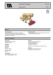
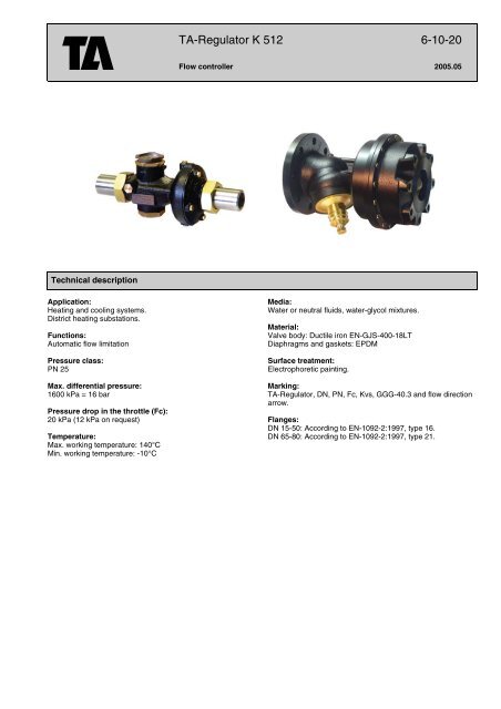
Application:<br />
Heating and cooling systems.<br />
District heating substations.<br />
Functions:<br />
Automatic flow limitation<br />
Pressure class:<br />
PN 25<br />
Max. differential pressure:<br />
1600 kPa = 16 bar<br />
Pressure drop in the throttle (Fc):<br />
<strong>20</strong> kPa (12 kPa on request)<br />
Temperature:<br />
Max. working temperature: 140°C<br />
Min. working temperature: -<strong>10</strong>°C<br />
<strong>TA</strong>-<strong>Regulator</strong> K <strong>512</strong> 6-<strong>10</strong>-<strong>20</strong><br />
Flow controller <strong>20</strong>05.05<br />
Media:<br />
Water or neutral fluids, water-glycol mixtures.<br />
Material:<br />
Valve body: Ductile iron EN-GJS-400-18LT<br />
Diaphragms and gaskets: EPDM<br />
Surface treatment:<br />
Electrophoretic painting.<br />
Marking:<br />
<strong>TA</strong>-<strong>Regulator</strong>, DN, PN, Fc, Kvs, GGG-40.3 and flow direction<br />
arrow.<br />
Flanges:<br />
DN 15-50: According to EN-<strong>10</strong>92-2:1997, type 16.<br />
DN 65-80: According to EN-<strong>10</strong>92-2:1997, type 21.
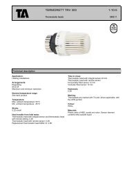
<strong>TA</strong>-<strong>Regulator</strong> K <strong>512</strong><br />
DN 15-50<br />
d<br />
DN 65-80<br />
L<br />
ØD<br />
Connections<br />
= Flow direction<br />
Connection with female thread<br />
For DN 15-50<br />
d2 d1<br />
L1<br />
Connection for welding<br />
For DN 15-50<br />
ØD d1<br />
Connection with flange<br />
For DN 15-50<br />
ØD<br />
L1<br />
L1<br />
L<br />
d1<br />
d<br />
ØD<br />
<strong>TA</strong> No DN d D L Kvs<br />
DN 65-80 are flanged and do not need any separate connections.<br />
6-<strong>10</strong>-<strong>20</strong> - 2<br />
q max<br />
m 3 /h Kg<br />
52 756-8<strong>20</strong> 15/<strong>20</strong> R1 78 1<strong>10</strong> 4,1 1,1 1,0<br />
52 756-832 25/32 R1 1/4 97 150 16 4 1,8<br />
52 756-850 40/50 R2 125 190 35 <strong>10</strong> 4,2<br />
52 756-865 65 - <strong>20</strong>0 190 70 <strong>20</strong> 22<br />
52 756-880 80 - <strong>20</strong>0 3<strong>10</strong> 70 24 24<br />
<strong>TA</strong> No d1 d2 L1<br />
52 759-015 G1 G1/2 26<br />
52 759-0<strong>20</strong> G1 G3/4 32<br />
52 759-025 G1 1/4 G1 47<br />
52 759-032 G1 1/4 G1 1/4 52<br />
52 759-040 G2 G1 1/2 52<br />
52 759-050 G2 G2 64,5<br />
<strong>TA</strong> No d1 D L1<br />
52 759-315 G1 <strong>20</strong>,8 37<br />
52 759-3<strong>20</strong> G1 26,3 42<br />
52 759-325 G1 1/4 33,2 47<br />
52 759-332 G1 1/4 40,9 47<br />
52 759-340 G2 48,0 47<br />
52 759-350 G2 60,0 52<br />
<strong>TA</strong> No d1 D L1<br />
52 759-515 G1 95 <strong>10</strong><br />
52 759-5<strong>20</strong> G1 <strong>10</strong>5 <strong>20</strong><br />
52 759-525 G1 1/4 115 5<br />
52 759-532 G1 1/4 140 15<br />
52 759-540 G2 150 5<br />
52 759-550 G2 165 <strong>20</strong>
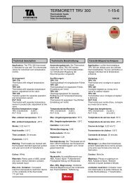
Operating function<br />
The throttle (2) for flow adjustment and inline flow controller (6) are built in series in one valve body (7). Pressure upstream of the<br />
throttle acts through internal capillary pipe (V+) to one side of diaphragm (8) in the flow controller and attempts to close it.<br />
Pressure downstream of the throttle acts through another internal impulse to the other side of the diaphragm and attempts to open<br />
the valve together with the spring force.<br />
The accuracy of flow regulation is practically independent on the pressures upstream and downstream of the regulator.<br />
V+ 1 2<br />
3 4 5 6<br />
1. Fixing nut<br />
2. Throttle<br />
3. Holes for plombing (throttle)<br />
4. Holes for plombing (valve body)<br />
5. Venting screws<br />
6. Flow controller<br />
7. Valve body<br />
8. Diaphragm<br />
9. Plug<br />
Installation<br />
Installation in supply or return pipe. Flow direction is shown by the arrow on the valve body. Installation of a strainer upstream of<br />
the valve is recommended. When filling, vent the body by using the venting screws. Instead of the plug R1/4 you can install drain<br />
valve or measurement point for pressure or temperature measurement.<br />
Setting<br />
9<br />
8<br />
Presetting of the maximum flow<br />
Release the fixing nut (1). Turn the throttle (2) clockwise down to the start position of 0,0 turns. Adjust the corresponding number<br />
of scale turns according to flow chart and the pointer (4) on the valve body. Tighten the fixing nut. You can plomb the flow setting<br />
using holes (3a and 3b) on the throttle and the valve body.<br />
a Measure the flow on the balancing valve S<strong>TA</strong>D using the balancing instrument <strong>TA</strong>-CBI or measuring instrument <strong>TA</strong>-CMI.<br />
b Adjust the throttle until you measure the required flow on the <strong>TA</strong>-CBI or <strong>TA</strong>-CMI.<br />
c Lock the fixing nut. When you lock the nut please hold the throttle in place with an allen key.<br />
Alternative:<br />
a Take the presetting value from the table which is packed with the valve.<br />
b Open the throttle anti-clockwise. The preset value (e.g. 3,4) means that you open the valve three complete turns. After that turn<br />
until the figure 4 fits the red mark on the valve body.<br />
c Lock the fixing nut. When you lock the nut hold the throttle in place with an allen key.<br />
1<br />
S<strong>TA</strong>D (S<strong>TA</strong>F)<br />
K <strong>512</strong><br />
3a<br />
2<br />
4<br />
3b<br />
7<br />
Table - Example<br />
6-<strong>10</strong>-<strong>20</strong> - 3
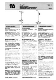
Sizing<br />
1. Select the smallest size for the flow you need in the diagram.<br />
2. Check that the available ∆p is bigger than the sum of the pressure drops calculated with the formula or use the diagram:<br />
6-<strong>10</strong>-<strong>20</strong> - 4
Balancing valve S<strong>TA</strong>D (PN <strong>20</strong>)<br />
For flow measuring<br />
Max 1<strong>20</strong>°C<br />
See catalogue leaflet S<strong>TA</strong>D, S<strong>TA</strong>DA,... for complete details.<br />
d<br />
Accessories<br />
*) Can be connected to smooth pipes by KOMBI compression coupling. See catalogue leaflet<br />
KOMBI under section Couplings.<br />
Balancing valve S<strong>TA</strong>F, S<strong>TA</strong>F-SG<br />
For flow measuring<br />
Max 1<strong>20</strong>°C<br />
See catalogue leaflet S<strong>TA</strong>F, S<strong>TA</strong>F-SG,... for complete details.<br />
Measuring point<br />
Max 1<strong>20</strong>°C (Intermittent 150°C)<br />
<strong>TA</strong> No <strong>TA</strong> No<br />
d = G1/2 d = G3/4<br />
52 151-<strong>20</strong>9* 52 151-609*<br />
52 151-214* 52 151-614*<br />
52 151-2<strong>20</strong>* 52 151-6<strong>20</strong>*<br />
52 151-225 52 151-625<br />
52 151-232 52 151-632<br />
52 151-240 52 151-640<br />
52 151-250 52 151-650<br />
<strong>TA</strong> No <strong>TA</strong> No DN<br />
PN 16 PN 25<br />
- 52 182-040** 40<br />
- 52 182-050** 50<br />
52 181-065 52 182-065 65<br />
52 181-080 52 182-080 80<br />
**) Fit PN 16 flanges.<br />
<strong>TA</strong> No L<br />
52 179-009 39<br />
52 179-609 <strong>10</strong>3<br />
Products for higher temperatures - contact <strong>TA</strong>.<br />
Other products, see <strong>TA</strong> Product catalogue section ”Balancing valves”.<br />
Tour & Andersson retains the right to make changes to its products and specifications without prior notice.<br />
6-<strong>10</strong>-<strong>20</strong> - 5
6-<strong>10</strong>-<strong>20</strong> - 6