Tour b Andersson AB - TA Hydronics
Tour b Andersson AB - TA Hydronics
Tour b Andersson AB - TA Hydronics

You also want an ePaper? Increase the reach of your titles
YUMPU automatically turns print PDFs into web optimized ePapers that Google loves.
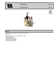
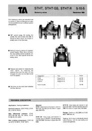
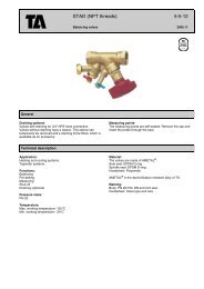
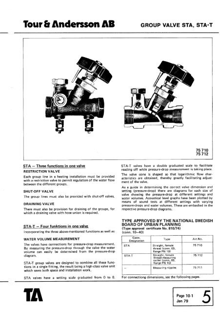
<strong>Tour</strong> b <strong>Andersson</strong> <strong>AB</strong> GROUP VALVE S<strong>TA</strong>, S<strong>TA</strong>-T<br />
S<strong>TA</strong> - Three functions in one valve<br />
RESTRICTION VALVE<br />
Each group line in a heating installation must be provided<br />
with a restriction valve to permit regulation of the water flow<br />
between the different groups.<br />
SHUT-OFF VALVE<br />
The group lines must also be provided with shut-off valves.<br />
DRAINING VALVE<br />
There must also be provision for draining of the groups, for<br />
which a draining valve with hose union is required.<br />
S<strong>TA</strong>-T - Four funktions in one valve<br />
Incorporating the three above-mentioned functions as well as:<br />
WATER VOLUME MEASUREMENT<br />
The valves have connections for pressure-drop measurement.<br />
By measuring the pressure-drop through the valve the water<br />
volume can easily be determined from the pressuredrop<br />
diagram.<br />
S<strong>TA</strong>-T group valves are designed to combine all these func-<br />
tions in a single fitting, the result being a high-class valve unit<br />
which saves both space and installation work.<br />
S<strong>TA</strong> valves have a setting scale graduated from O to 8.<br />
S<strong>TA</strong>-T valves have a double graduated scale to facilitate<br />
reading off while pressure-drop measurement is taking place.<br />
The valve cone is shaped so that logarithmic flow char-<br />
acteristics are obtained, thereby greatly facilitating adjust-<br />
ment of the valve.<br />
As a guide in determining the correct valve dimension and<br />
setti-ng (pressure-drop) there are diagrams for each size of<br />
valve showing the pressure-drop at different settings and<br />
water volumes. Acoustical level graphs have been plotted by<br />
means of sound tests at different settings with varying<br />
pressure-drops and water volumes. These are embodied in the<br />
respective pressure-drop diagrams.<br />
TYPE APPROVED BY THE NATIONAL SWEDISH<br />
BOARD OF URBAN PLANNING<br />
(Type approval certif icate No. 81 0174)<br />
(conn. 10-40)<br />
Conn.<br />
Designation<br />
TY pe<br />
Art.No.<br />
I S<strong>TA</strong> Straight, female<br />
I thread (conn. 65, 1 75710 I<br />
S<strong>TA</strong>-T<br />
-<br />
flange PN 10)<br />
Straight, female<br />
th read measuri ng<br />
outlet (conn. 65,<br />
flange PN 101 .<br />
I I I I<br />
For connectiong dimensions, see the following pages.<br />
Page 10-1<br />
Jan 79 5<br />
75 712<br />
Measuring nipples 75 711<br />
I
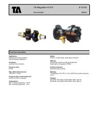
TECHNICAL DESCRIPTION<br />
LA,I<br />
Application :<br />
Nominal pressure:<br />
Max. working pressure:<br />
Max. working temperature:<br />
Detachable measuring nipples. Art.No. 75 7 1 1-000<br />
Material :<br />
Draining:<br />
Testing:<br />
Packi ng:<br />
Patent:<br />
Heating installations. Conn. 10-40 also for potable water in-<br />
stallations.<br />
Conn. 10-40 PN 16<br />
Conn. 50-65 PN 10<br />
Conn. 10-40 16 bar = 1.6 MPa = 225 psi<br />
Conn. 50-65 10 bar = 1 .O MPa 150 psi<br />
Conn. 10-40 + 150° C<br />
Conn. 50-65 + 120' C<br />
Conn. 10-40 made of AM E<strong>TA</strong>L throughout.<br />
Conn. 58-65 with valve body of cast iron (SIS 01 25) and<br />
ohter parts of copper alloy (SIS 5170). Valve cone with<br />
resilient seal. Valves provided with red nylon knob.<br />
Draining unit suitable for hose socket (with washer) and wing<br />
nut. Valves supplied with protective Cap but excluding hose<br />
socket.<br />
Each valve is individually tested before despatch, both for<br />
seat sealing and overall leak-tightness.<br />
The valves are always packed in cartons in accordance with<br />
the carton packing liit, see under flap 13.<br />
75 710 and 75 71 2 are protected by patent.<br />
Conn.<br />
DN<br />
10<br />
15<br />
2 0<br />
2 5<br />
32<br />
40<br />
50<br />
Flanges<br />
PN 10<br />
10<br />
15<br />
20<br />
2 5<br />
32<br />
40<br />
50<br />
Flanges<br />
PN 10<br />
Bjorsell, Bor&<br />
7
<strong>Tour</strong> b <strong>Andersson</strong> <strong>AB</strong> GROUP VALVE S<strong>TA</strong>, S<strong>TA</strong>-T<br />
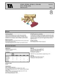
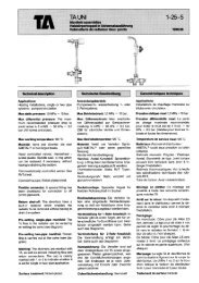
Presetting S<strong>TA</strong><br />
Initial setting of a new valve fora particular pressure-<br />
drop, e.g. corresponding to digit 5 on the diagram,<br />
is done as follows:<br />
1. Close the valve fully (Fig. 1 ).<br />
2. Slacken the lock nut of the scale.<br />
3. Turn the scale clockwise so that the desired pre-<br />
setting digit 5 comes opposite the indicator of the<br />
knob (Fig. 2).<br />
4. Tighten the lock nut.<br />
5. Open the valve until the indicator comes up<br />
against the stop shoulder (Fig. 3). The valve is<br />
now preset.<br />
To check the presetting of a valve, close it fully,<br />
when the indicator of the knob shows the presetting<br />
digit, in this case 5 (Fig. 2).<br />
As a guide in determining the correct valve dimen-<br />
sion and setting (pressure-drop) there are diagrams<br />
for each size of valve showing the pressure-drop at<br />
different settings and water volumes.<br />
Acoustical level graphs have been plotted by means<br />
of sound tests at different settings with varying<br />
pressure-drops and water volumes. These are<br />
embodied in the respective pressured rop diagram.<br />
Fig. 1<br />
Fig. 2<br />
Fig. 3<br />
I ndicator of<br />
.knob<br />
Scal e-<br />
Lock nut<br />
Stop shoulder<br />
Page 10-3<br />
Jan 79 5
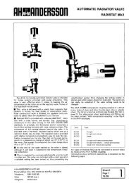
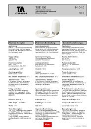
I ndicator of knob<br />
Stop shoulder<br />
Fig. 3A. Valve closed Fig. 3B. Valve opened Fig. 3C. Valve opened<br />
- not preset. to presetting 6. fully to presetting<br />
made.<br />
Regulation of water volumes<br />
The actual pressuredrops in the<br />
group lines of a heating system are<br />
difficult to establish by calculation,<br />
meaning that the water volume -<br />
and thereby also the heat distribu-<br />
tion - is often incorrect in practice.<br />
With the S<strong>TA</strong>-T valve it is easy to<br />
regulate the desired water volume.<br />
By measuring the pressuredrop<br />
across the valve at a particular pre-<br />
setting value the water volume for<br />
the size of valve concerned can be<br />
read off from the pressureddrop<br />
diagram.<br />
Preparations for measu ring<br />
Valve<br />
1. Close the valve fully, when it<br />
must not be connected to the<br />
gauge.<br />
2. Slacken the scale dial lock nut.<br />
3. Turn the dial so that the digit O<br />
on the INNER scale comes<br />
opposite the indicator of the<br />
knob (Fig. 3A).<br />
4. Tighten the lock nut.<br />
5. Open the valve to the desired<br />
presetting value, e.g. 6, by turn-<br />
ing the knob until its indicator<br />
comes opposite 6 on the INNER<br />
scale (Fig. 3B).<br />
Gauge<br />
1. Use a differential pressure gauge<br />
DTM. Valves 1, 2 and 3 should<br />
be closed until measurement is<br />
started.<br />
2. Connect the hoses to the nipples<br />
on the S<strong>TA</strong>-T valvehose from<br />
outlet S to the outlet side.<br />
3. Open nipples N about one turn<br />
and then open valve 1 on the<br />
gauge. Water circulation now<br />
aslo takes place past the S<strong>TA</strong>-T<br />
valve and air is forced out in the<br />
hoses.<br />
5 Page<br />
10-4<br />
Jan 79<br />
Wait a moment until the hoses<br />
are vented, open valves 2 and 3<br />
and slowly close valve 1.<br />
The pressuredrop in the S<strong>TA</strong>-T<br />
valve can now be read off in<br />
metres water column directly on<br />
the scale of the gauge. Max. 6.3<br />
metres water column.<br />
Fig. 4. Close-up view of<br />
Measuring differential pressure gauge<br />
Checking water volume at DTM.<br />
specified presetting<br />
If a particular presetting value- has<br />
been specified, e.g. 6, turn the knob<br />
so that its indicator points to 6 on<br />
the INNER scale (Fig. 36). Measure<br />
the pressure-drop as described<br />
above and read off the water<br />
volume through the valve at setting<br />
6 in the pressuredrop diagram.<br />
If the water volume does not agree<br />
with that desired, select another<br />
valve setting - still using the<br />
INNER scale - and repeat the<br />
measuring procedure until the<br />
correct water volume has been<br />
obtained.<br />
Where no presetting is<br />
specif ied<br />
If no presetting value is specified,<br />
select a suitable valve opening,<br />
measure the pressured rop and<br />
Fig. 6<br />
Fig. 5. Gauge hoses con-<br />
nected to valve nipples.<br />
Specified water volume<br />
in litres per hour<br />
S<strong>TA</strong>-T<br />
determine the water volume. If the<br />
water volume does not agree with<br />
that required, reset the valve and<br />
repeat the measuring procedure<br />
until the correct water volume has<br />
been obtained.<br />
NOTE. While carrying out measure-<br />
ment the S<strong>TA</strong>-T valve must not<br />
be fully closed if the gauge<br />
valves 2 and 3 are open. If the<br />
valve has to be closed, the valves<br />
on the gauge must be closed<br />
first, otherwise there is a risk<br />
that the mercury will be blown<br />
out. During transport valves 2<br />
and 3 must be closed.<br />
Fixing of presetting position<br />
When the correct presetting position<br />
has been obtained it is fixed as<br />
follows:<br />
1. Slacken the scale dial lock nut.<br />
2. Turn the dial clockwise until the<br />
stop shoulder comes up against<br />
the indicator of the knob (when<br />
the position of the knob must<br />
not be altered).<br />
3. Tighten the lock nut, when the<br />
maximum opening of the valve<br />
is now limited to the presetting<br />
made, e.g. 6. See Fig. 3C.<br />
The valve dial has a hole close to<br />
the stop shoulder whereby leadsealing<br />
of the set position can be<br />
made. If it is required to check the<br />
valve setting, close the valve fully,<br />
when the indicator of the knob will<br />
show the presetting value on the<br />
OUTER scale.<br />
Fig. 7. Differential pressure gauge<br />
DTM connected to S<strong>TA</strong>-T valve.