9-5-5 GB TA SHUNT.fm - TA Hydronics
9-5-5 GB TA SHUNT.fm - TA Hydronics
9-5-5 GB TA SHUNT.fm - TA Hydronics

You also want an ePaper? Increase the reach of your titles
YUMPU automatically turns print PDFs into web optimized ePapers that Google loves.
General<br />
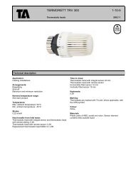
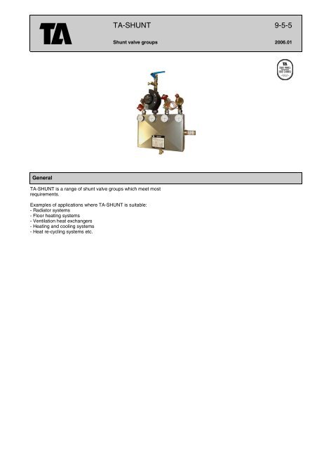
<strong>TA</strong>-<strong>SHUNT</strong> is a range of shunt valve groups which meet most<br />
requirements.<br />
Examples of applications where <strong>TA</strong>-<strong>SHUNT</strong> is suitable:<br />
- Radiator systems<br />
- Floor heating systems<br />
- Ventilation heat exchangers<br />
- Heating and cooling systems<br />
- Heat re-cycling systems etc.<br />
<strong>TA</strong>-<strong>SHUNT</strong> 9-5-5<br />
Shunt valve groups 2006.01
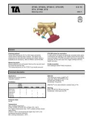
Technical description<br />
Applications:<br />
<strong>TA</strong>-<strong>SHUNT</strong> is made for the following types of control circuits:<br />
1. Constant flow in primary and secondary circuit.<br />
2. Variable flow in primary circuit and constant flow in secondary circuit.<br />
3. Variable flow in primary circuit and constant flow in secondary circuit for installations without a main pump.<br />
4. Constant flow in primary and secondary circuit and where the control valve loads the secondary circuit, so-called Norwegian<br />
coupling.<br />
5. Water-borne heat recycling with variable flow in the air inlet circuit and constant flow in the outlet air circuit.<br />
6. Variable flow in primary circuit and constant flow in secondary circuit (SABO coupling).<br />
7. Variable flow in primary circuit and constant flow in secondary circuit. Keeping the differential pressure over a control valve<br />
constant.<br />
<strong>TA</strong>-<strong>SHUNT</strong> can be used in systems with up to 50% glycol content.<br />
Pressure class:<br />
PN 6<br />
All components in the shunt valve group are classified to at least PN 6. If PN 10 is needed, please specify this when ordering.<br />
Temperature:<br />
Max media temperature: 95°C<br />
Min media temperature: -10°C<br />
Certain pumps require special versions.<br />
Union dimension:<br />
DN 20 - 100<br />
Gate and ball valves:<br />
DN 20-50: <strong>TA</strong> 500 Ball valve<br />
DN 65-100: <strong>TA</strong> 60 Gate valve<br />
Balancing valves:<br />
DN 10-50 S<strong>TA</strong>D<br />
DN 65-100 S<strong>TA</strong>F<br />
DN 15-100 S<strong>TA</strong>P<br />
Control valves:<br />
2-way: V222, V241.<br />
3-way: V321, V341.<br />
Kvs control valves:<br />
0,25 - 160 in the Renard series.<br />
Pipe packages:<br />
DN 20-50 according to ISO 65 (Carbon steel tubes suitable for screwing in accordance with ISO 7/1).<br />
DN 65-100 pressure vessel pipes, seamless Stainless steel or copper pipe packages can be tendered on request.<br />
Thermometers:<br />
Graduated 0-120°C for heating. -40°C - +40°C for cooling/recycling.<br />
Insulation:<br />
Heating: Non-combustible mineral wool<br />
Cooling: Armaflex condensate insulation<br />
Protective box:<br />
DN 20-100: Plastic-coated sheet metal box.<br />
Circulation pump:<br />
<strong>TA</strong>-<strong>SHUNT</strong> can be equipped with Grundfos, WILO, Flygt etc. pumps as standard.<br />
Non-return valve:<br />
With spring-loaded valve disc.<br />
9-5-5 - 2
Mechanical construction<br />
General<br />
<strong>TA</strong>-<strong>SHUNT</strong> is made in all sizes from DN 20 to DN 100. In addition to the basic types, shunt valve types can be made to customer<br />
specification, such as larger than DN 100. Installation can be done in different ways, which gives considerable flexibility. Shunt<br />
valve groups can be installed upside down, for example. You just have to remember that the control valve spindle must never point<br />
downwards.<br />
Shunt valve groups up to DN 50 are connected by means of pipe threads. DN 65 and larger are connected by means of flanged<br />
joints.<br />
NOTE! Mating flanges are supplied for flanged joints.<br />
Control valves<br />
The shunt valve groups are designed for use with <strong>TA</strong>C AB control valves, but can also be ordered with other makes.<br />
The specifications are found in the documentation provided by each make.<br />
Control equipment and actuators for control valves are not included.<br />
Balancing<br />
Primary and secondary circuits return pipes are provided with <strong>TA</strong>'s balancing valves, S<strong>TA</strong>D up to DN 50 and S<strong>TA</strong>F as from<br />
DN 65. The valves have measurement points, draining (S<strong>TA</strong>D) and also function as shut-off valves. When used for balancing and<br />
controlling media flow, please refer to the separate catalogue for S<strong>TA</strong>D, S<strong>TA</strong>F.<br />
To keep the differential pressure over a control valve constant, S<strong>TA</strong>P/S<strong>TA</strong>D(S<strong>TA</strong>F) are used. See Principle coupling 7.<br />
Shut-offs<br />
Primary and secondary circuits inlet connections are provided with shut-off valves. For DN 20-50, shunt valve groups for heat are<br />
provided with ball valves with a raised lever. Shunt valve groups for cooling are provided with geared ball valves.<br />
DN 65-100 are provided with ball-type gate valves.<br />
Measurement connections:<br />
The shunt valve groups are provided with measurement connections on the primary and secondary circuits inlet pipes, to permit<br />
measurement of available pressure and pressure drop in connected circuits.<br />
Pump<br />
<strong>TA</strong>-<strong>SHUNT</strong> is normally delivered with a circulation pump for the secondary circuit. The pump is installed in the supply pipe outside<br />
the box, but inside the shut-off valve. The location outside the box makes the pump easily accessible for service or repair, and the<br />
pump motor gets good cooling, which also ensures longer endurance.<br />
Threaded pumps are supplied ready installed in the valve groups. Flanged pumps are not mounted when supplied, in order to<br />
avoid making the valve groups unnecessarily bulky and heavy. Installation has been prepared by <strong>TA</strong>, however, and is easy to do<br />
on site with the installation components provided.<br />
Shunt valve groups can also be supplied, prepared for pump installation, which means that the installation components<br />
accompany the pump. Finally, shunt valve groups can be supplied without either pumps or preparation for pumps.<br />
Insulation - box<br />
Shunt valve groups from DN 20 to DN 100 are insulated as standard with non-flammable mineral wool for heating systems and<br />
with Armaflex condensation insulation on shunt valve groups intended for refrigerant transmission systems.<br />
External valves with couplings or flanges are not insulated.<br />
The shunt valve groups are provided with a plastic-coated sheet metal box, which is easy to dismantle for inspection.<br />
Mounting<br />
A bracket for wall mounting is included as standard for all shunt valve groups. DN 65 and larger also have muffs underneath for<br />
support feet, if used. A floor mounting stand is available as an option, but the muffs for support legs are then omitted.<br />
Type plate<br />
A self-adhesive type plate is fixed to the front of the box. The type plate includes the following:<br />
- Pos specifies the section of the installation which the shunt valve group serves<br />
- Type gives the characteristic data of the shunt valve group<br />
- Year of manufacture<br />
- Max pressure and temperature<br />
- Pump type and data are specified for pumps delivered with the shunt valve group<br />
- Principle coupling is given, with a connection diagram<br />
Document pocket<br />
There is an A5-format document pocket on the rear of the shunt valve group.<br />
Non-return valve<br />
In shunt valve groups where a non-return valve is included, it consists of a spring-loaded valve disc with low opening pressure and<br />
low forward pressure drop.<br />
Thermometers<br />
4 thermometers are installed in each shunt valve group. The thermometers for heating are graduated 0-120°C and for cold/heat<br />
recycling they are graduated -40°C - +40°C.<br />
Draining<br />
The shunt valve groups are equipped with a separate drain device, SAV with R1/2 for hose connection. If the shunt valve group<br />
is installed so that the SAV is uppermost, it can be used for venting.<br />
9-5-5 - 3
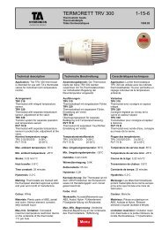
Dimension sketch<br />
Shunt valve<br />
group DN A B C D F G K L<br />
20 150 35 145 120 310 430 90 100 9<br />
25 170 45 170 170 415 600 100 110 17<br />
32 170 45 190 170 415 600 100 110 20<br />
40 220 55 200 220 530 770 120 140 30<br />
50 220 55 250 220 530 770 120 140 37<br />
Dimensions can vary, depending on version. If the relevant dimensions have to be verified, please contact closest sales office.<br />
*) 2-way control valve<br />
**) 3-way control valve<br />
***) Excl pump<br />
9-5-5 - 4<br />
Weight***<br />
kg<br />
65 230 75 350 230 640 840 165 200 90-130<br />
80 280 80 380 280 780 1000 180 230 180-230<br />
100 310* 110 420 310 900 1150 200 260 210-280<br />
400**
Valve table - control valves<br />
2-way valves<br />
Designation Characteristic Kvs DN <strong>TA</strong> No<br />
V241 EQM 0,25 15 54 241-115<br />
” ” 0,40 15 54 241-215<br />
” ” 0,63 15 54 241-315<br />
” ” 1,0 15 54 241-415<br />
” ” 1,6 15 54 241-515<br />
” ” 2,5 15 54 241-615<br />
” ” 4,0 15 54 241-715<br />
” ” 6,3 20 54 241-820<br />
” ” 10 25 54 241-725<br />
” ” 16 32 54 241-532<br />
” ” 25 40 54 241-540<br />
” ” 38 50 54 241-550<br />
V222 EQ% 63 65 54 222-665<br />
” ” 100 80 54 222-780<br />
” ” 160 100 54 222-990<br />
3-way valves<br />
Designation Characteristic Kvs DN <strong>TA</strong> No<br />
V341 EQM-Komp 1,6 15 54 341-515<br />
” ” 2,5 15 54 341-615<br />
” ” 4,0 15 54 341-715<br />
” ” 6,3 20 54 341-820<br />
” ” 10 25 54 341-725<br />
” ” 16 32 54 341-532<br />
” ” 25 40 54 341-540<br />
” ” 38 50 54 341-550<br />
V321 EQ%-Komp 63 65 54 321-665<br />
” ” 100 80 54 321-680<br />
” ” 160 100 54 321-690<br />
Coding template<br />
V341 - 4,0 / 20V - 11 - 0,30 / 11 - 0,30 / 4,8<br />
Control valve 2-way<br />
V241 - Kvs see valve table<br />
V222 - Kvs see valve table<br />
Control valve 3-way<br />
V341 - Kvs see valve table<br />
V321 - Kvs see valve table<br />
Shunt valve group DN 20 - DN 100<br />
V = Heat insulated<br />
K = Cold insulated<br />
Connection procedure<br />
See principle couplings 1-6<br />
Flow primary circuit l/sec<br />
Pressure drop primary circuit kPa<br />
Flow secondary circuit l/sec<br />
Pressure drop secondary circuit kPa<br />
9-5-5 - 5
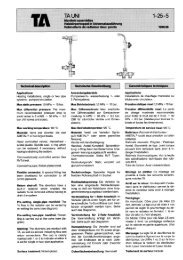
Calculation example<br />
DN 20<br />
- - - - - - = Pressure drop with fully open balancing valve across<br />
Secondary circuit<br />
Principle coupling 1, 2 and 5.<br />
Primary circuit<br />
Principal coupling 3, 4 and 6.<br />
Item 3<br />
11 kPa on<br />
primary side<br />
Item 2<br />
4,8 kPa<br />
Background:<br />
- A shunt valve group is to be connected to a heat exchanger with constant flow in primary and secondary circuits.<br />
- The connection should be on the top of the shunt valve group for both primary and secondary circuits, with the primary circuit on<br />
the left.<br />
- The shunt valve group shall be equipped with a circulation pump, 1x230V, in the secondary circuit.<br />
- The shunt valve group shall be mounted on a floor stand.<br />
- Primary coupling:<br />
Available pressure 15 kPa<br />
Required flow 0.3 l/s<br />
- Secondary coupling:<br />
Pressure drop across secondary side outside the shunt valve group with required flow = 20 kPa<br />
Required flow 0.3 l/s<br />
- Control valve: <strong>TA</strong>C 3-way<br />
A proposed solution is given below, which moves forward one step at a time to derive coding which complies with the appearance<br />
of the coding templates. In the calculation example below, the unknown values are replaced by x, and are successively replaced<br />
by the derived values.<br />
Coding: Vxxx-x.x/xxV-xx-0.30/xx-0.30/xx<br />
9-5-5 - 6<br />
Dimensioning<br />
flow<br />
4.0 = Control valve<br />
Kvs value<br />
Available pressure,<br />
primary side,<br />
in example = 15 kPa
Solution:<br />
1 Start by choosing the principle coupling and version. Principle coupling 1, shunt valve group 11, complies with the background<br />
conditions.<br />
Coding: Vxxx-x.x/xxV-11-0.30/xx-0.30/xx<br />
2 Choose shunt valve group size. Flow 0.3 l/s gives size DN 20, please refer to the diagram. First read off the secondary pressure<br />
drop across the shunt valve group, with the balancing valve fully open, to 4.8 kPa.<br />
Coding: Vxxx-x.x/20V-11-0.30/xx-0.30/4.8<br />
3 Now select the control valve. The pressure drop shown by the slanting lines in the diagrams applies to the entire shunt valve<br />
group primary side i.e. both the control and balancing valves. Both valves are fully open.<br />
The Kv values beside the slanting lines specify the Kvs values you should select for the control valve. They do not refer to the Kv<br />
value for the line they are on.<br />
Go up in the diagram to the relevant flow, 0.3 l/s. Select the Kvs value for the control valve which gives the next lower pressure<br />
drop in the shunt valve group compared with available pressure. A Kvs value of 4.0 for the control valve gives a total pressure drop<br />
of 11 kPa on the primary side. This pressure drop is deducted from available pressure, 15 kPa. The difference, 4.0 kPa, is<br />
controlled by the balancing valve on the primary side. In the valve table, you see that the valve is referred to as V341. This has a<br />
threaded spindle end and can be motorised by most makes of control.<br />
The entire coding can now be written:<br />
Coding: V341-4.0/20V-11-0.30/11-0.30/4.8<br />
This coding will be marked on the type plate and contains the following information:<br />
- Type of control valve<br />
- Kvs value<br />
- Union dimension<br />
- Type of insulation<br />
- Connection procedure<br />
- Projected primary flow<br />
- Min necessary available primary pressure<br />
- Projected secondary flow<br />
- Secondary pressure drop across the valve group<br />
4 Select pump for secondary circuit. Pump data is available from each manufacturer’s catalogue.<br />
The lift height which the pump must provide is determined by pipe losses and equipment outside the shunt valve group, plus the<br />
pressure drop across the secondary side of the shunt valve group with the balancing valve fully open. In the example, this gives<br />
20 kPa plus 4.8 kPa i.e. 24.8 kPa. The flow should be 0.3 l/s. For example, select Grundfos pump UPS 25-40 130 1x 230V. At<br />
0.3 l/s, this gives 28 kPa.<br />
Or select Wilo Star - RS 25/4 1x230V. At 0.3 l/s, this gives 30 kPa. The surplus pressure is controlled by the balancing valve on<br />
the secondary side.<br />
5 Select any accessories, in this example one floor stand for DN 20.<br />
6 Summarise the information:<br />
1 shunt valve group, V341-4.0/20V-11-0.30/11-0.30/4.8<br />
1 Grundfos pump, UPS25-40 130 1 x 230V, or Wilo Star - RS 25/4 1 x 230V<br />
1 floor stand DN 20<br />
Support material<br />
Calculation program<br />
<strong>TA</strong>-<strong>SHUNT</strong>: Simplifies the choice of pump, control valve and balancing valve for shunt valve groups.<br />
Manual<br />
Manual no 1: Balancing of control circuits.<br />
9-5-5 - 7
Principle coupling 1: Constant flow in primary and secondary circuit<br />
<strong>TA</strong>-<strong>SHUNT</strong> connection procedure 11, 12, 13 , 14, 15 and 16.<br />
For conventional heating and ventilation systems with main pump and where you want high return temperature to the boiler.<br />
This circuit is also used in cooling installations and floor heating installations. The flow in the secondary circuit can be greater<br />
than, or equal to the flow in primary circuit. The control valve functions as a mixing valve on the primary circuit return.<br />
For other connection procedures than those below - please contact closest sales office.<br />
a)<br />
Shunt valve group 11<br />
M<br />
Shunt valve group 12<br />
Shunt valve group 13<br />
P<br />
c)<br />
P S<br />
S<br />
P<br />
M<br />
M<br />
S<br />
DN<br />
<strong>TA</strong> No<br />
Heating<br />
<strong>TA</strong> No<br />
Cooling<br />
20 54 111-120 54 161-120<br />
25 54 111-125 54 161-125<br />
32 54 111-132 54 161-132<br />
40 54 111-140 54 161-140<br />
50 54 111-150 54 161-150<br />
65 54 111-165 54 161-165<br />
80 54 111-180 54 161-180<br />
100 54 111-190 54 161-190<br />
DN<br />
<strong>TA</strong> No<br />
Heating<br />
<strong>TA</strong> No<br />
Cooling<br />
20 54 111-220 54 161-220<br />
25 54 111-225 54 161-225<br />
32 54 111-232 54 161-232<br />
40 54 111-240 54 161-240<br />
50 54 111-250 54 161-250<br />
65 54 111-265 54 161-265<br />
80 54 111-280 54 161-280<br />
100 54 111-290 54 161-290<br />
DN<br />
d)<br />
<strong>TA</strong> No<br />
Heating<br />
<strong>TA</strong> No<br />
Cooling<br />
20 54 111-320 54 161-320<br />
25 54 111-325 54 161-325<br />
32 54 111-332 54 161-332<br />
40 54 111-340 54 161-340<br />
50 54 111-350 54 161-350<br />
65 54 111-365 54 161-365<br />
80 54 111-380 54 161-380<br />
100 54 111-390 54 161-390<br />
9-5-5 - 8<br />
b)<br />
a) Boiler or calorifier<br />
b) Heating group or air heater/cooler<br />
c) Main pump - primary<br />
d) Pump - secondary
Shunt valve group 14<br />
Shunt valve group 15<br />
M<br />
S<br />
P<br />
Shunt valve group 16<br />
S<br />
S<br />
M<br />
P<br />
P = Primary side<br />
S = Secondary side<br />
M<br />
P<br />
DN<br />
<strong>TA</strong> No<br />
Heating<br />
<strong>TA</strong> No<br />
Cooling<br />
20 54 111-420 54 161-420<br />
25 54 111-425 54 161-425<br />
32 54 111-432 54 161-432<br />
40 54 111-440 54 161-440<br />
50 54 111-450 54 161-450<br />
65 54 111-465 54 161-465<br />
80 54 111-480 54 161-480<br />
100 54 111-490 54 161-490<br />
DN<br />
<strong>TA</strong> No<br />
Heating<br />
<strong>TA</strong> No<br />
Cooling<br />
20 54 111-520 54 161-520<br />
25 54 111-525 54 161-525<br />
32 54 111-532 54 161-532<br />
40 54 111-540 54 161-540<br />
50 54 111-550 54 161-550<br />
65 54 111-565 54 161-565<br />
80 54 111-580 54 161-580<br />
100 54 111-590 54 161-590<br />
DN<br />
<strong>TA</strong> No<br />
Heating<br />
<strong>TA</strong> No<br />
Cooling<br />
20 54 111-620 54 161-620<br />
25 54 111-625 54 161-625<br />
32 54 111-632 54 161-632<br />
40 54 111-640 54 161-640<br />
50 54 111-650 54 161-650<br />
65 54 111-665 54 161-665<br />
80 54 111-680 54 161-680<br />
100 54 111-690 54 161-690<br />
9-5-5 - 9
Principle coupling 2: Variable flow in primary circuit and constant flow in secondary circuit<br />
<strong>TA</strong>-<strong>SHUNT</strong> connection procedure 21, 22, 23, 24, 25 and 26.<br />
For installations connected to district heating networks or other installations where low return temperature is required. The flow<br />
in the secondary circuit can be greater than or equal to the flow in the primary circuit. A 2-way control valve is located in the primary<br />
side return pipe.<br />
For other connection procedures than those below - please contact closest sales office.<br />
a) b)<br />
Shunt valve group 21<br />
M<br />
Shunt valve group 22<br />
Shunt valve group 23<br />
P<br />
c)<br />
S<br />
P S<br />
P<br />
M<br />
M<br />
S<br />
DN<br />
<strong>TA</strong> No<br />
Heating<br />
<strong>TA</strong> No<br />
Cooling<br />
20 54 112-120 54 162-120<br />
25 54 112-125 54 162-125<br />
32 54 112-132 54 162-132<br />
40 54 112-140 54 162-140<br />
50 54 112-150 54 162-150<br />
65 54 112-165 54 162-165<br />
80 54 112-180 54 162-180<br />
100 54 112-190 54 162-190<br />
DN<br />
<strong>TA</strong> No<br />
Heating<br />
<strong>TA</strong> No<br />
Cooling<br />
20 54 112-220 54 162-220<br />
25 54 112-225 54 162-225<br />
32 54 112-232 54 162-232<br />
40 54 112-240 54 162-240<br />
50 54 112-250 54 162-250<br />
65 54 112-265 54 162-265<br />
80 54 112-280 54 162-280<br />
100 54 112-290 54 162-290<br />
DN<br />
d)<br />
<strong>TA</strong> No<br />
Heating<br />
<strong>TA</strong> No<br />
Cooling<br />
20 54 112-320 54 162-320<br />
25 54 112-325 54 162-325<br />
32 54 112-332 54 162-332<br />
40 54 112-340 54 162-340<br />
50 54 112-350 54 162-350<br />
65 54 112-365 54 162-365<br />
80 54 112-380 54 162-380<br />
100 54 112-390 54 162-390<br />
9-5-5 - 10<br />
a) Boiler or calorifier<br />
b) Heating group or air heater/cooler<br />
c) Main pump - primary<br />
d) Pump - secondary
Shunt valve group 24<br />
Shunt valve group 25<br />
M<br />
S<br />
P<br />
Shunt valve group 26<br />
S<br />
S<br />
M<br />
P<br />
P = Primary side<br />
S = Secondary side<br />
M<br />
P<br />
DN<br />
<strong>TA</strong> No<br />
Heating<br />
<strong>TA</strong> No<br />
Cooling<br />
20 54 112-420 54 162-420<br />
25 54 112-425 54 162-425<br />
32 54 112-432 54 162-432<br />
40 54 112-440 54 162-440<br />
50 54 112-450 54 162-450<br />
65 54 112-465 54 162-465<br />
80 54 112-480 54 162-480<br />
100 54 112-490 54 162-490<br />
DN<br />
<strong>TA</strong> No<br />
Heating<br />
<strong>TA</strong> No<br />
Cooling<br />
20 54 112-520 54 162-520<br />
25 54 112-525 54 162-525<br />
32 54 112-532 54 162-532<br />
40 54 112-540 54 162-540<br />
50 54 112-550 54 162-550<br />
65 54 112-565 54 162-565<br />
80 54 112-580 54 162-580<br />
100 54 112-590 54 162-590<br />
DN<br />
<strong>TA</strong> No<br />
Heating<br />
<strong>TA</strong> No<br />
Cooling<br />
20 54 112-620 54 162-620<br />
25 54 112-625 54 162-625<br />
32 54 112-632 54 162-632<br />
40 54 112-640 54 162-640<br />
50 54 112-650 54 162-650<br />
65 54 112-665 54 162-665<br />
80 54 112-680 54 162-680<br />
100 54 112-690 54 162-690<br />
9-5-5 - 11
<strong>TA</strong>-<strong>SHUNT</strong> connection procedure 31, 32, 33, 34, 35 and 36.<br />
This shunt valve group is generally used in installations without a main pump or in installations with low available pressure.<br />
The control valve functions as a mixing valve in the inlet pipe.<br />
NOTE! The following applies to dimensioning of the pressure drop diagrams: The primary side pressure drop applies to the<br />
secondary side. The secondary side pressure drop applies to the primary side. The flow should be equal in primary and secondary<br />
circuits.<br />
For other connection procedures than those below - please contact closest sales office.<br />
Shunt valve group 31<br />
Shunt valve group 32<br />
Shunt valve group 33<br />
P<br />
Principle coupling 3: Variable flow in primary circuit and constant flow in secondary circuit<br />
a) b)<br />
P S<br />
S<br />
P<br />
S<br />
DN<br />
<strong>TA</strong> No<br />
Heating<br />
<strong>TA</strong> No<br />
Cooling<br />
20 54 113-120 54 163-120<br />
25 54 113-125 54 163-125<br />
32 54 113-132 54 163-132<br />
40 54 113-140 54 163-140<br />
50 54 113-150 54 163-150<br />
65 54 113-165 54 163-165<br />
80 54 113-180 54 163-180<br />
100 54 113-190 54 163-190<br />
DN<br />
<strong>TA</strong> No<br />
Heating<br />
<strong>TA</strong> No<br />
Cooling<br />
20 54 113-220 54 163-220<br />
25 54 113-225 54 163-225<br />
32 54 113-232 54 163-232<br />
40 54 113-240 54 163-240<br />
50 54 113-250 54 163-250<br />
65 54 113-265 54 163-265<br />
80 54 113-280 54 163-280<br />
100 54 113-290 54 163-290<br />
DN<br />
d)<br />
<strong>TA</strong> No<br />
Heating<br />
<strong>TA</strong> No<br />
Cooling<br />
20 54 113-320 54 163-320<br />
25 54 113-325 54 163-325<br />
32 54 113-332 54 163-332<br />
40 54 113-340 54 163-340<br />
50 54 113-350 54 163-350<br />
65 54 113-365 54 163-365<br />
80 54 113-380 54 163-380<br />
100 54 113-390 54 163-390<br />
9-5-5 - 12<br />
a) Boiler or calorifier<br />
b) Heating group or air heater/cooler<br />
d) Pump - secondary
Shunt valve group 34<br />
S<br />
Shunt valve group 35<br />
Shunt valve group 36<br />
S<br />
P<br />
S<br />
P<br />
P = Primary side<br />
S = Secondary side<br />
P<br />
DN<br />
<strong>TA</strong> No<br />
Heating<br />
<strong>TA</strong> No<br />
Cooling<br />
20 54 113-420 54 163-420<br />
25 54 113-425 54 163-425<br />
32 54 113-432 54 163-432<br />
40 54 113-440 54 163-440<br />
50 54 113-450 54 163-450<br />
65 54 113-465 54 163-465<br />
80 54 113-480 54 163-480<br />
100 54 113-490 54 163-490<br />
DN<br />
<strong>TA</strong> No<br />
Heating<br />
<strong>TA</strong> No<br />
Cooling<br />
20 54 113-520 54 163-520<br />
25 54 113-525 54 163-525<br />
32 54 113-532 54 163-532<br />
40 54 113-540 54 163-540<br />
50 54 113-550 54 163-550<br />
65 54 113-565 54 163-565<br />
80 54 113-580 54 163-580<br />
100 54 113-590 54 163-590<br />
DN<br />
<strong>TA</strong> No<br />
Heating<br />
<strong>TA</strong> No<br />
Cooling<br />
20 54 113-620 54 163-620<br />
25 54 113-625 54 163-625<br />
32 54 113-632 54 163-632<br />
40 54 113-640 54 163-640<br />
50 54 113-650 54 163-650<br />
65 54 113-665 54 163-665<br />
80 54 113-680 54 163-680<br />
100 54 113-690 54 163-690<br />
9-5-5 - 13
Principle coupling 4: Constant flow in primary and secondary circuit (Norwegian coupling)<br />
<strong>TA</strong>-<strong>SHUNT</strong> connection procedure 41, 42, 43, 44, 45 and 46.<br />
Used for shunting of heating or cooling water in radiators, ventilation or cooling circuits etc. The connection is intended for<br />
systems with a main pump. The flow in the primary circuit can be greater than or equal to the flow in the secondary circuit. The<br />
control valve functions as a mixing valve in the secondary side inlet pipe.<br />
NOTE! The following applies to dimensioning of the pressure drop diagrams: The primary side pressure drop applies to the<br />
secondary side. The secondary side pressure drop applies to the primary side.<br />
For other connection procedures than those below - please contact closest sales office.<br />
a)<br />
Shunt valve group 41<br />
Shunt valve group 42<br />
M<br />
Shunt valve group 43<br />
P<br />
P<br />
c)<br />
S<br />
S<br />
M<br />
P<br />
M<br />
S<br />
DN<br />
<strong>TA</strong> No<br />
Heating<br />
<strong>TA</strong> No<br />
Cooling<br />
20 54 114-120 54 164-120<br />
25 54 114-125 54 164-125<br />
32 54 114-132 54 164-132<br />
40 54 114-140 54 164-140<br />
50 54 114-150 54 164-150<br />
65 54 114-165 54 164-165<br />
80 54 114-180 54 164-180<br />
100 54 114-190 54 164-190<br />
DN<br />
<strong>TA</strong> No<br />
Heating<br />
<strong>TA</strong> No<br />
Cooling<br />
20 54 114-220 54 164-220<br />
25 54 114-225 54 164-225<br />
32 54 114-232 54 164-232<br />
40 54 114-240 54 164-240<br />
50 54 114-250 54 164-250<br />
65 54 114-265 54 164-265<br />
80 54 114-280 54 164-280<br />
100 54 114-290 54 164-290<br />
DN<br />
d)<br />
<strong>TA</strong> No<br />
Heating<br />
<strong>TA</strong> No<br />
Cooling<br />
20 54 114-320 54 164-320<br />
25 54 114-325 54 164-325<br />
32 54 114-332 54 164-332<br />
40 54 114-340 54 164-340<br />
50 54 114-350 54 164-350<br />
65 54 114-365 54 164-365<br />
80 54 114-380 54 164-380<br />
100 54 114-390 54 164-390<br />
9-5-5 - 14<br />
b)<br />
a) Boiler or calorifier<br />
b) Heating group or air heater/cooler<br />
c) Main pump - primary<br />
d) Pump - secondary
Shunt valve group 44<br />
Shunt valve group 45<br />
M<br />
S<br />
S<br />
Shunt valve group 46<br />
P<br />
P<br />
M<br />
S<br />
P = Primary side<br />
S = Secondary side<br />
M<br />
P<br />
DN<br />
<strong>TA</strong> No<br />
Heating<br />
<strong>TA</strong> No<br />
Cooling<br />
20 54 114-420 54 164-420<br />
25 54 114-425 54 164-425<br />
32 54 114-432 54 164-432<br />
40 54 114-440 54 164-440<br />
50 54 114-450 54 164-450<br />
65 54 114-465 54 164-465<br />
80 54 114-480 54 164-480<br />
100 54 114-490 54 164-490<br />
DN<br />
<strong>TA</strong> No<br />
Heating<br />
<strong>TA</strong> No<br />
Cooling<br />
20 54 114-520 54 164-520<br />
25 54 114-525 54 164-525<br />
32 54 114-532 54 164-532<br />
40 54 114-540 54 164-540<br />
50 54 114-550 54 164-550<br />
65 54 114-565 54 164-565<br />
80 54 114-580 54 164-580<br />
100 54 114-590 54 164-590<br />
DN<br />
<strong>TA</strong> No<br />
Heating<br />
<strong>TA</strong> No<br />
Cooling<br />
20 54 114-620 54 164-620<br />
25 54 114-625 54 164-625<br />
32 54 114-632 54 164-632<br />
40 54 114-640 54 164-640<br />
50 54 114-650 54 164-650<br />
65 54 114-665 54 164-665<br />
80 54 114-680 54 164-680<br />
100 54 114-690 54 164-690<br />
9-5-5 - 15
Principle coupling 5: Variable flow in air inlet circuit and constant flow in air outlet circuit<br />
<strong>TA</strong>-<strong>SHUNT</strong> connection procedure 51, 52, 53, 54, 55 and 56.<br />
This shunt valve group is intended for heat recycling systems. The control valve functions as a mixing valve in the primary side<br />
inlet pipe. When you dimension the pump, the dimensioning flow should be used in both heat exchangers. The pump must be able<br />
to manage the pressure drop across both heat exchangers, the pipe system and the control valve.<br />
For other connection procedures than those below - please contact closest sales office.<br />
e) f)<br />
h)<br />
Shunt valve group 51<br />
Shunt valve group 52<br />
M<br />
Shunt valve group 53<br />
TL<br />
TL<br />
FL<br />
FL TL<br />
M<br />
M<br />
FL<br />
DN<br />
<strong>TA</strong> No<br />
Heating<br />
<strong>TA</strong> No<br />
Cooling<br />
20 54 115-120 54 165-120<br />
25 54 115-125 54 165-125<br />
32 54 115-132 54 165-132<br />
40 54 115-140 54 165-140<br />
50 54 115-150 54 165-150<br />
65 54 115-165 54 165-165<br />
80 54 115-180 54 165-180<br />
100 54 115-190 54 165-190<br />
DN<br />
<strong>TA</strong> No<br />
Heating<br />
<strong>TA</strong> No<br />
Cooling<br />
20 54 115-220 54 165-220<br />
25 54 115-225 54 165-225<br />
32 54 115-232 54 165-232<br />
40 54 115-240 54 165-240<br />
50 54 115-250 54 165-250<br />
65 54 115-265 54 165-265<br />
80 54 115-280 54 165-280<br />
100 54 115-290 54 165-290<br />
DN<br />
g)<br />
<strong>TA</strong> No<br />
Heating<br />
<strong>TA</strong> No<br />
Cooling<br />
20 54 115-320 54 165-320<br />
25 54 115-325 54 165-325<br />
32 54 115-332 54 165-332<br />
40 54 115-340 54 165-340<br />
50 54 115-350 54 165-350<br />
65 54 115-365 54 165-365<br />
80 54 115-380 54 165-380<br />
100 54 115-390 54 165-390<br />
9-5-5 - 16<br />
e) Heat exchanger in air inlet duct<br />
f) Heat exchanger in air outlet duct<br />
g) Pump<br />
h) Expansion vessel
Shunt valve group 54<br />
Shunt valve group 55<br />
M<br />
FL<br />
Shunt valve group 56<br />
FL<br />
TL<br />
M<br />
FL<br />
TL<br />
FL = Air outlet<br />
TL = Air inlet<br />
M<br />
TL<br />
DN<br />
<strong>TA</strong> No<br />
Heating<br />
<strong>TA</strong> No<br />
Cooling<br />
20 54 115-420 54 165-420<br />
25 54 115-425 54 165-425<br />
32 54 115-432 54 165-432<br />
40 54 115-440 54 165-440<br />
50 54 115-450 54 165-450<br />
65 54 115-465 54 165-465<br />
80 54 115-480 54 165-480<br />
100 54 115-490 54 165-490<br />
DN<br />
<strong>TA</strong> No<br />
Heating<br />
<strong>TA</strong> No<br />
Cooling<br />
20 54 115-520 54 165-520<br />
25 54 115-525 54 165-525<br />
32 54 115-532 54 165-532<br />
40 54 115-540 54 165-540<br />
50 54 115-550 54 165-550<br />
65 54 115-565 54 165-565<br />
80 54 115-580 54 165-580<br />
100 54 115-590 54 165-590<br />
DN<br />
<strong>TA</strong> No<br />
Heating<br />
<strong>TA</strong> No<br />
Cooling<br />
20 54 115-620 54 165-620<br />
25 54 115-625 54 165-625<br />
32 54 115-632 54 165-632<br />
40 54 115-640 54 165-640<br />
50 54 115-650 54 165-650<br />
65 54 115-665 54 165-665<br />
80 54 115-680 54 165-680<br />
100 54 115-690 54 165-690<br />
9-5-5 - 17
Principle coupling 6: Variable flow in primary circuit and constant flow in secondary circuit (Sabo coupling)<br />
<strong>TA</strong>-<strong>SHUNT</strong> connection procedure 61, 62, 63, 64 , 65 and 66.<br />
This shunt valve group is used in low flow systems with large temperature differences and low pressure drop in the shunt valve<br />
group.<br />
NOTE! The following applies to dimensioning of the pressure drop diagrams: The primary side pressure drop applies to the<br />
secondary side. The secondary side pressure drop applies to the primary side.<br />
The control valve functions as a mixing valve in the inlet pipe.<br />
For other connection procedures than those below - please contact closest sales office.<br />
a)<br />
Shunt valve group 61<br />
Shunt valve group 62<br />
M<br />
Shunt valve group 63<br />
P<br />
P S<br />
S<br />
M<br />
P<br />
M<br />
S<br />
DN<br />
<strong>TA</strong> No<br />
Heating<br />
<strong>TA</strong> No<br />
Cooling<br />
20 54 116-120 54 166-120<br />
25 54 116-125 54 166-125<br />
32 54 116-132 54 166-132<br />
40 54 116-140 54 166-140<br />
50 54 116-150 54 166-150<br />
65 54 116-165 54 166-165<br />
80 54 116-180 54 166-180<br />
100 54 116-190 54 166-190<br />
DN<br />
<strong>TA</strong> No<br />
Heating<br />
<strong>TA</strong> No<br />
Cooling<br />
20 54 116-220 54 166-220<br />
25 54 116-225 54 166-225<br />
32 54 116-232 54 166-232<br />
40 54 116-240 54 166-240<br />
50 54 116-250 54 166-250<br />
65 54 116-265 54 166-265<br />
80 54 116-280 54 166-280<br />
100 54 116-290 54 166-290<br />
DN<br />
d)<br />
<strong>TA</strong> No<br />
Heating<br />
<strong>TA</strong> No<br />
Cooling<br />
20 54 116-320 54 166-320<br />
25 54 116-325 54 166-325<br />
32 54 116-332 54 166-332<br />
40 54 116-340 54 166-340<br />
50 54 116-350 54 166-350<br />
65 54 116-365 54 166-365<br />
80 54 116-380 54 166-380<br />
100 54 116-390 54 166-390<br />
9-5-5 - 18<br />
b)<br />
a) Boiler or calorifier<br />
b) Heating group or air heater/cooler<br />
d) Pump - secondary
Shunt valve group 64<br />
Shunt valve group 65<br />
M<br />
S<br />
Shunt valve group 66<br />
S<br />
P<br />
S<br />
P<br />
M<br />
P = Primary side<br />
S = Secondary side<br />
M<br />
P<br />
DN<br />
<strong>TA</strong> No<br />
Heating<br />
<strong>TA</strong> No<br />
Cooling<br />
20 54 116-420 54 166-420<br />
25 54 116-425 54 166-425<br />
32 54 116-432 54 166-432<br />
40 54 116-440 54 166-440<br />
50 54 116-450 54 166-450<br />
65 54 116-465 54 166-465<br />
80 54 116-480 54 166-480<br />
100 54 116-490 54 166-490<br />
DN<br />
<strong>TA</strong> No<br />
Heating<br />
<strong>TA</strong> No<br />
Cooling<br />
20 54 116-520 54 166-520<br />
25 54 116-525 54 166-525<br />
32 54 116-532 54 166-532<br />
40 54 116-540 54 166-540<br />
50 54 116-550 54 166-550<br />
65 54 116-565 54 166-565<br />
80 54 116-580 54 166-580<br />
100 54 116-590 54 166-590<br />
DN<br />
<strong>TA</strong> No<br />
Heating<br />
<strong>TA</strong> No<br />
Cooling<br />
20 54 116-620 54 166-620<br />
25 54 116-625 54 166-625<br />
32 54 116-632 54 166-632<br />
40 54 116-640 54 166-640<br />
50 54 116-650 54 166-650<br />
65 54 116-665 54 166-665<br />
80 54 116-680 54 166-680<br />
100 54 116-690 54 166-690<br />
9-5-5 - 19
Principle coupling 7: Variable flow in primary circuit and constant flow in secondary circuit. Keeping the<br />
differential pressure over a control valve constant.<br />
<strong>TA</strong>-<strong>SHUNT</strong> connection procedure 71, 72, 73, 74, 75 and 76.<br />
For installations connected to district heating networks or other installations where low return temperature is required. The flow<br />
in the secondary circuit can be greater than or equal to the flow in the primary circuit. A 2-way control valve is located in the primary<br />
side return pipe.<br />
Depending of the design of the plant, the available differential pressure across some circuits can vary significantly with the load.<br />
To keep the correct control valve characteristic in such a case, the differential pressure across the control valves can be kept<br />
almost constant by a S<strong>TA</strong>P connected directly across each control valve. The control valve will not be over-sized and the authority<br />
is and will remain close to 1.<br />
S<strong>TA</strong>P keeps ∆p across the control valve constant, giving a valve authority ~ 1.<br />
The Kvs of the control valve and the chosen ∆p gives the design flow.<br />
S<strong>TA</strong>D is used for flow measuring, shut-off and connection of the signal pipe.<br />
For other connection procedures than those below - please contact closest sales office.<br />
a) b)<br />
Shunt valve group 21<br />
M<br />
Shunt valve group 22<br />
S<br />
c)<br />
P S<br />
P<br />
M<br />
DN<br />
<strong>TA</strong> No<br />
Heating<br />
<strong>TA</strong> No<br />
Cooling<br />
20 54 117-120 54 167-120<br />
25 54 117-125 54 167-125<br />
32 54 117-132 54 167-132<br />
40 54 117-140 54 167-140<br />
50 54 117-150 54 167-150<br />
65 54 117-165 54 167-165<br />
80 54 117-180 54 167-180<br />
100 54 117-190 54 167-190<br />
DN<br />
<strong>TA</strong> No<br />
Heating<br />
d)<br />
<strong>TA</strong> No<br />
Cooling<br />
20 54 117-220 54 167-220<br />
25 54 117-225 54 167-225<br />
32 54 117-232 54 167-232<br />
40 54 117-240 54 167-240<br />
50 54 117-250 54 167-250<br />
65 54 117-265 54 167-265<br />
80 54 117-280 54 167-280<br />
100 54 117-290 54 167-290<br />
9-5-5 - 20<br />
a) Boiler or calorifier<br />
b) Heating group or air heater/cooler<br />
c) Main pump - primary<br />
d) Pump - secondary
Shunt valve group 23<br />
P<br />
Shunt valve group 24<br />
Shunt valve group 25<br />
M<br />
S<br />
P<br />
Shunt valve group 26<br />
S<br />
M<br />
S<br />
P<br />
M<br />
P = Primary side<br />
S = Secondary side<br />
M<br />
S<br />
P<br />
DN<br />
<strong>TA</strong> No<br />
Heating<br />
<strong>TA</strong> No<br />
Cooling<br />
20 54 117-320 54 167-320<br />
25 54 117-325 54 167-325<br />
32 54 117-332 54 167-332<br />
40 54 117-340 54 167-340<br />
50 54 117-350 54 167-350<br />
65 54 117-365 54 167-365<br />
80 54 117-380 54 167-380<br />
100 54 117-390 54 167-390<br />
DN<br />
<strong>TA</strong> No<br />
Heating<br />
<strong>TA</strong> No<br />
Cooling<br />
20 54 117-420 54 167-420<br />
25 54 117-425 54 167-425<br />
32 54 117-432 54 167-432<br />
40 54 117-440 54 167-440<br />
50 54 117-450 54 167-450<br />
65 54 117-465 54 167-465<br />
80 54 117-480 54 167-480<br />
100 54 117-490 54 167-490<br />
DN<br />
<strong>TA</strong> No<br />
Heating<br />
<strong>TA</strong> No<br />
Cooling<br />
20 54 117-520 54 167-520<br />
25 54 117-525 54 167-525<br />
32 54 117-532 54 167-532<br />
40 54 117-540 54 167-540<br />
50 54 117-550 54 167-550<br />
65 54 117-565 54 167-565<br />
80 54 117-580 54 167-580<br />
100 54 117-590 54 167-590<br />
DN<br />
<strong>TA</strong> No<br />
Heating<br />
<strong>TA</strong> No<br />
Cooling<br />
20 54 117-620 54 167-620<br />
25 54 117-625 54 167-625<br />
32 54 117-632 54 167-632<br />
40 54 117-640 54 167-640<br />
50 54 117-650 54 167-650<br />
65 54 117-665 54 167-665<br />
80 54 117-680 54 167-680<br />
100 54 117-690 54 167-690<br />
NOTE! Diagram for Princip coupling 7 will be available in February 2006.<br />
9-5-5 - 21
Diagram DN 20<br />
- - - - - - = Pressure drop with fully open balancing valve across<br />
Secondary circuit<br />
Principle coupling 1, 2 and 5.<br />
Primary circuit<br />
Principle coupling 3, 4 and 6.<br />
9-5-5 - 22
Diagram DN 25<br />
- - - - - - = Pressure drop with fully open balancing valve across<br />
Secondary circuit<br />
Principle coupling 1, 2 and 5.<br />
Primary circuit<br />
Principle coupling 3, 4 and 6.<br />
9-5-5 - 23
Diagram DN 32<br />
- - - - - - = Pressure drop with fully open balancing valve across<br />
Secondary circuit<br />
Principle coupling 1, 2 and 5.<br />
Primary circuit<br />
Principle coupling 3, 4 and 6.<br />
9-5-5 - 24
Diagram DN 40<br />
- - - - - - = Pressure drop with fully open balancing valve across<br />
Secondary circuit<br />
Principle coupling 1, 2 and 5.<br />
Primary circuit<br />
Principle coupling 3, 4 and 6.<br />
9-5-5 - 25
Diagram DN 50<br />
- - - - - - = Pressure drop with fully open balancing valve across<br />
Secondary circuit<br />
Principle coupling 1, 2 and 5.<br />
Primary circuit<br />
Principle coupling 3, 4 and 6.<br />
9-5-5 - 26
Diagram DN 65<br />
- - - - - - = Pressure drop with fully open balancing valve across<br />
Secondary circuit<br />
Principle coupling 1, 2 and 5.<br />
Primary circuit<br />
Principle coupling 3, 4 and 6.<br />
9-5-5 - 27
Diagram DN 80<br />
- - - - - - = Pressure drop with fully open balancing valve across<br />
Secondary circuit<br />
Principle coupling 1, 2 and 5.<br />
Primary circuit<br />
Principle coupling 3, 4 and 6.<br />
9-5-5 - 28
Diagram DN 100<br />
- - - - - - = Pressure drop with fully open balancing valve across<br />
Secondary circuit<br />
Principle coupling 1, 2 and 5.<br />
Primary circuit<br />
Principle coupling 3, 4 and 6.<br />
9-5-5 - 29
Tour & Andersson retains the right to make changes to its products and specifications without prior notice.<br />
9-5-5 - 30