9-5-5 GB TA SHUNT.fm - TA Hydronics
9-5-5 GB TA SHUNT.fm - TA Hydronics
9-5-5 GB TA SHUNT.fm - TA Hydronics

You also want an ePaper? Increase the reach of your titles
YUMPU automatically turns print PDFs into web optimized ePapers that Google loves.
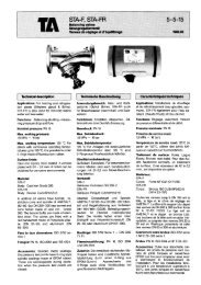
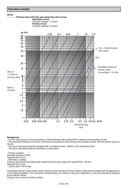
Calculation example<br />
DN 20<br />
- - - - - - = Pressure drop with fully open balancing valve across<br />
Secondary circuit<br />
Principle coupling 1, 2 and 5.<br />
Primary circuit<br />
Principal coupling 3, 4 and 6.<br />
Item 3<br />
11 kPa on<br />
primary side<br />
Item 2<br />
4,8 kPa<br />
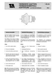
Background:<br />
- A shunt valve group is to be connected to a heat exchanger with constant flow in primary and secondary circuits.<br />
- The connection should be on the top of the shunt valve group for both primary and secondary circuits, with the primary circuit on<br />
the left.<br />
- The shunt valve group shall be equipped with a circulation pump, 1x230V, in the secondary circuit.<br />
- The shunt valve group shall be mounted on a floor stand.<br />
- Primary coupling:<br />
Available pressure 15 kPa<br />
Required flow 0.3 l/s<br />
- Secondary coupling:<br />
Pressure drop across secondary side outside the shunt valve group with required flow = 20 kPa<br />
Required flow 0.3 l/s<br />
- Control valve: <strong>TA</strong>C 3-way<br />
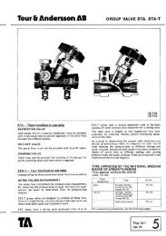
A proposed solution is given below, which moves forward one step at a time to derive coding which complies with the appearance<br />
of the coding templates. In the calculation example below, the unknown values are replaced by x, and are successively replaced<br />
by the derived values.<br />
Coding: Vxxx-x.x/xxV-xx-0.30/xx-0.30/xx<br />
9-5-5 - 6<br />
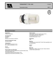
Dimensioning<br />
flow<br />
4.0 = Control valve<br />
Kvs value<br />
Available pressure,<br />
primary side,<br />
in example = 15 kPa