9-5-5 GB TA SHUNT.fm - TA Hydronics
9-5-5 GB TA SHUNT.fm - TA Hydronics
9-5-5 GB TA SHUNT.fm - TA Hydronics

You also want an ePaper? Increase the reach of your titles
YUMPU automatically turns print PDFs into web optimized ePapers that Google loves.
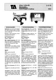
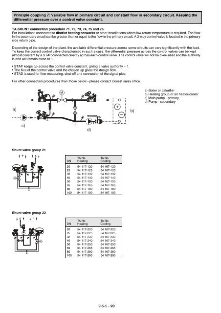
Principle coupling 7: Variable flow in primary circuit and constant flow in secondary circuit. Keeping the<br />
differential pressure over a control valve constant.<br />
<strong>TA</strong>-<strong>SHUNT</strong> connection procedure 71, 72, 73, 74, 75 and 76.<br />
For installations connected to district heating networks or other installations where low return temperature is required. The flow<br />
in the secondary circuit can be greater than or equal to the flow in the primary circuit. A 2-way control valve is located in the primary<br />
side return pipe.<br />
Depending of the design of the plant, the available differential pressure across some circuits can vary significantly with the load.<br />
To keep the correct control valve characteristic in such a case, the differential pressure across the control valves can be kept<br />
almost constant by a S<strong>TA</strong>P connected directly across each control valve. The control valve will not be over-sized and the authority<br />
is and will remain close to 1.<br />
S<strong>TA</strong>P keeps ∆p across the control valve constant, giving a valve authority ~ 1.<br />
The Kvs of the control valve and the chosen ∆p gives the design flow.<br />
S<strong>TA</strong>D is used for flow measuring, shut-off and connection of the signal pipe.<br />
For other connection procedures than those below - please contact closest sales office.<br />
a) b)<br />
Shunt valve group 21<br />
M<br />
Shunt valve group 22<br />
S<br />
c)<br />
P S<br />
P<br />
M<br />
DN<br />
<strong>TA</strong> No<br />
Heating<br />
<strong>TA</strong> No<br />
Cooling<br />
20 54 117-120 54 167-120<br />
25 54 117-125 54 167-125<br />
32 54 117-132 54 167-132<br />
40 54 117-140 54 167-140<br />
50 54 117-150 54 167-150<br />
65 54 117-165 54 167-165<br />
80 54 117-180 54 167-180<br />
100 54 117-190 54 167-190<br />
DN<br />
<strong>TA</strong> No<br />
Heating<br />
d)<br />
<strong>TA</strong> No<br />
Cooling<br />
20 54 117-220 54 167-220<br />
25 54 117-225 54 167-225<br />
32 54 117-232 54 167-232<br />
40 54 117-240 54 167-240<br />
50 54 117-250 54 167-250<br />
65 54 117-265 54 167-265<br />
80 54 117-280 54 167-280<br />
100 54 117-290 54 167-290<br />
9-5-5 - 20<br />
a) Boiler or calorifier<br />
b) Heating group or air heater/cooler<br />
c) Main pump - primary<br />
d) Pump - secondary