Tour b Andersson AB - TA Hydronics
Tour b Andersson AB - TA Hydronics
Tour b Andersson AB - TA Hydronics

Create successful ePaper yourself
Turn your PDF publications into a flip-book with our unique Google optimized e-Paper software.
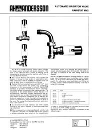
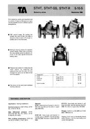
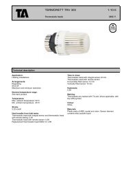
I ndicator of knob<br />
Stop shoulder<br />
Fig. 3A. Valve closed Fig. 3B. Valve opened Fig. 3C. Valve opened<br />
- not preset. to presetting 6. fully to presetting<br />
made.<br />
Regulation of water volumes<br />
The actual pressuredrops in the<br />
group lines of a heating system are<br />
difficult to establish by calculation,<br />
meaning that the water volume -<br />
and thereby also the heat distribu-<br />
tion - is often incorrect in practice.<br />
With the S<strong>TA</strong>-T valve it is easy to<br />
regulate the desired water volume.<br />
By measuring the pressuredrop<br />
across the valve at a particular pre-<br />
setting value the water volume for<br />
the size of valve concerned can be<br />
read off from the pressureddrop<br />
diagram.<br />
Preparations for measu ring<br />
Valve<br />
1. Close the valve fully, when it<br />
must not be connected to the<br />
gauge.<br />
2. Slacken the scale dial lock nut.<br />
3. Turn the dial so that the digit O<br />
on the INNER scale comes<br />
opposite the indicator of the<br />
knob (Fig. 3A).<br />
4. Tighten the lock nut.<br />
5. Open the valve to the desired<br />
presetting value, e.g. 6, by turn-<br />
ing the knob until its indicator<br />
comes opposite 6 on the INNER<br />
scale (Fig. 3B).<br />
Gauge<br />
1. Use a differential pressure gauge<br />
DTM. Valves 1, 2 and 3 should<br />
be closed until measurement is<br />
started.<br />
2. Connect the hoses to the nipples<br />
on the S<strong>TA</strong>-T valvehose from<br />
outlet S to the outlet side.<br />
3. Open nipples N about one turn<br />
and then open valve 1 on the<br />
gauge. Water circulation now<br />
aslo takes place past the S<strong>TA</strong>-T<br />
valve and air is forced out in the<br />
hoses.<br />
5 Page<br />
10-4<br />
Jan 79<br />
Wait a moment until the hoses<br />
are vented, open valves 2 and 3<br />
and slowly close valve 1.<br />
The pressuredrop in the S<strong>TA</strong>-T<br />
valve can now be read off in<br />
metres water column directly on<br />
the scale of the gauge. Max. 6.3<br />
metres water column.<br />
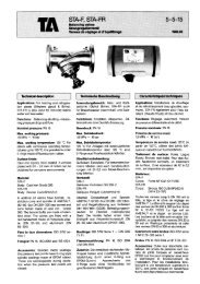
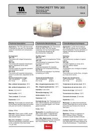
Fig. 4. Close-up view of<br />
Measuring differential pressure gauge<br />
Checking water volume at DTM.<br />
specified presetting<br />
If a particular presetting value- has<br />
been specified, e.g. 6, turn the knob<br />
so that its indicator points to 6 on<br />
the INNER scale (Fig. 36). Measure<br />
the pressure-drop as described<br />
above and read off the water<br />
volume through the valve at setting<br />
6 in the pressuredrop diagram.<br />
If the water volume does not agree<br />
with that desired, select another<br />
valve setting - still using the<br />
INNER scale - and repeat the<br />
measuring procedure until the<br />
correct water volume has been<br />
obtained.<br />
Where no presetting is<br />
specif ied<br />
If no presetting value is specified,<br />
select a suitable valve opening,<br />
measure the pressured rop and<br />
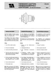
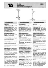
Fig. 6<br />
Fig. 5. Gauge hoses con-<br />
nected to valve nipples.<br />
Specified water volume<br />
in litres per hour<br />
S<strong>TA</strong>-T<br />
determine the water volume. If the<br />
water volume does not agree with<br />
that required, reset the valve and<br />
repeat the measuring procedure<br />
until the correct water volume has<br />
been obtained.<br />
NOTE. While carrying out measure-<br />
ment the S<strong>TA</strong>-T valve must not<br />
be fully closed if the gauge<br />
valves 2 and 3 are open. If the<br />
valve has to be closed, the valves<br />
on the gauge must be closed<br />
first, otherwise there is a risk<br />
that the mercury will be blown<br />
out. During transport valves 2<br />
and 3 must be closed.<br />
Fixing of presetting position<br />
When the correct presetting position<br />
has been obtained it is fixed as<br />
follows:<br />
1. Slacken the scale dial lock nut.<br />
2. Turn the dial clockwise until the<br />
stop shoulder comes up against<br />
the indicator of the knob (when<br />
the position of the knob must<br />
not be altered).<br />
3. Tighten the lock nut, when the<br />
maximum opening of the valve<br />
is now limited to the presetting<br />
made, e.g. 6. See Fig. 3C.<br />
The valve dial has a hole close to<br />
the stop shoulder whereby leadsealing<br />
of the set position can be<br />
made. If it is required to check the<br />
valve setting, close the valve fully,<br />
when the indicator of the knob will<br />
show the presetting value on the<br />
OUTER scale.<br />
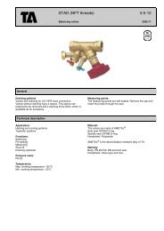
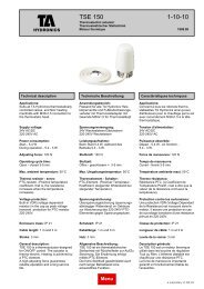
Fig. 7. Differential pressure gauge<br />
DTM connected to S<strong>TA</strong>-T valve.