- Page 1: MODEL BASED CONTROL OPTIMISATION OF
- Page 4 and 5: IV ABSTRACT - For optimised control
- Page 6 and 7: ACKNOWLEDGEMENTS VI ACKNOWLEDGEMENT
- Page 8 and 9: TABLE OF CONTENT VIII TABLE OF CONT
- Page 10 and 11: X TABLE OF CONTENT 4.5 ANALYSIS AND
- Page 12 and 13: XII TABLE OF CONTENT 6.2 MODEL BASE
- Page 14 and 15: NOMENCLATURE Latin letters A [m²]
- Page 16 and 17: Greek Letters α [W/m² K] heat tra
- Page 18 and 19: wb wet bulb Abbreviations ACM Absor
- Page 20 and 21: Page - 2 - CHAPTER 01 a thermal coo
- Page 22 and 23: Page - 4 - CHAPTER 01 explains the
- Page 24 and 25: Page - 6 - CHAPTER 01 The concept o
- Page 26 and 27: Page - 8 - CHAPTER 01 Mean calculat
- Page 28 and 29: Page - 10 - CHAPTER 01 analysed in
- Page 30 and 31: 2. MODEL DEVELOPMENT FOR SOLAR COOL
- Page 32 and 33: Page - 14 - CHAPTER 02 In the prese
- Page 34 and 35: Page - 16 - CHAPTER 02 Within chapt
- Page 36 and 37: Page - 18 - CHAPTER 02 b) Simple on
- Page 38 and 39: Page - 20 - CHAPTER 02 is off. For
- Page 40 and 41: Page - 22 - CHAPTER 02 Since only s
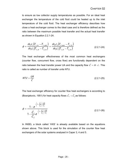
- Page 44 and 45: 2.2.1.4 Tubing Page - 26 - CHAPTER
- Page 46 and 47: tube fl fl tube tubel Page - 28 - C
- Page 48 and 49: Temperature / °C 90 80 70 60 50 40
- Page 50 and 51: TH 8 9 Qc & C G E Qe & Fig. 2-6: Sy
- Page 52 and 53: Page - 34 - CHAPTER 02 The enthalpy
- Page 54 and 55: Page - 36 - CHAPTER 02 With: Heat l
- Page 56 and 57: Page - 38 - CHAPTER 02 The so calle
- Page 58 and 59: Page - 40 - CHAPTER 02 To further i
- Page 60 and 61: Page - 42 - CHAPTER 02 2.2.2.2 Para
- Page 62 and 63: e e Page - 44 - CHAPTER 02 The char
- Page 64 and 65: Page - 46 - CHAPTER 02 and chapter
- Page 66 and 67: Model for the dynamic parts of the
- Page 68 and 69: - Absorber/Condenser Q g _ ac & & Q
- Page 70 and 71: Page - 52 - CHAPTER 02 cross sectio
- Page 72 and 73: Page - 54 - CHAPTER 02 conditions l
- Page 74 and 75: With: tw,in tw,out twb Water inlet
- Page 76 and 77: l min m& = m& a w = c ( h − h ) a
- Page 78 and 79: Page - 60 - CHAPTER 02 If the cooli
- Page 80 and 81: Page - 62 - CHAPTER 02 As already d
- Page 82 and 83: Page - 64 - CHAPTER 02 only very fe
- Page 84 and 85: Page - 66 - CHAPTER 02 rejection sy
- Page 86 and 87: Page - 68 - CHAPTER 02 and the UA v
- Page 88 and 89: Page - 70 - CHAPTER 02 different ve
- Page 90 and 91: Page - 72 - CHAPTER 02 −4 −2 2
- Page 92 and 93:
Page - 74 - CHAPTER 02 Fig. 2-25: M
- Page 94 and 95:
Page - 76 - CHAPTER 02 difference i
- Page 96 and 97:
Page - 78 - CHAPTER 02 In this quit
- Page 98 and 99:
- Absorbed solar energy Gt , a t a
- Page 100 and 101:
CHAPTER 02 Page - 82 - a b a r a a
- Page 102 and 103:
Page - 84 - CHAPTER 02 The area rel
- Page 104 and 105:
Page - 86 - CHAPTER 03 conditions.
- Page 106 and 107:
Page - 88 - CHAPTER 03 was calculat
- Page 108 and 109:
Page - 90 - CHAPTER 03 The same bui
- Page 110 and 111:
Page - 92 - CHAPTER 03 The specific
- Page 112 and 113:
Cooling / Heating power / kW 50 40
- Page 114 and 115:
Page - 96 - CHAPTER 03 As visible f
- Page 116 and 117:
3.4.2 SOLAR THERMAL SYSTEM MODELS P
- Page 118 and 119:
Page - 100 - CHAPTER 03 generator i
- Page 120 and 121:
m² kW-1 m² kW-1 Page - 102 - CHAP
- Page 122 and 123:
Page - 104 - CHAPTER 03 Fig. 3-16:
- Page 124 and 125:
Page - 106 - CHAPTER 03 m 2 kW -1 s
- Page 126 and 127:
Page - 108 - CHAPTER 03 Fig. 3-20:
- Page 128 and 129:
a f N d ( 1 + d ) ( 1 + d ) − 1 P
- Page 130 and 131:
Page - 112 - CHAPTER 03 costs Csola
- Page 132 and 133:
Page - 114 - CHAPTER 03 Fig. 3-26:
- Page 134 and 135:
Page - 116 - CHAPTER 03 The total a
- Page 136 and 137:
Page - 118 - CHAPTER 04 4. Model Ba
- Page 138 and 139:
Page - 120 - CHAPTER 04 Germany. De
- Page 140 and 141:
Page - 122 - CHAPTER 04 Fig. 4-2: A
- Page 142 and 143:
Page - 124 - CHAPTER 04 4.3.2 SYSTE
- Page 144 and 145:
Page - 126 - CHAPTER 04 temperature
- Page 146 and 147:
Page - 128 - CHAPTER 04 System part
- Page 148 and 149:
Page - 130 - CHAPTER 04 performance
- Page 150 and 151:
Fig. 4-5: Measured and simulated pe
- Page 152 and 153:
Page - 134 - CHAPTER 04 An addition
- Page 154 and 155:
Fig. 4-6: Annual electricity consum
- Page 156 and 157:
Page - 138 - CHAPTER 04 The values
- Page 158 and 159:
Page - 140 - CHAPTER 04 EAW WERACAL
- Page 160 and 161:
4.4.6 CONCLUSIONS Page - 142 - CHAP
- Page 162 and 163:
Page - 144 - CHAPTER 04 4.5 Analysi
- Page 164 and 165:
4.5.2 SIMULATION MODEL AND VALIDATI
- Page 166 and 167:
Page - 148 - CHAPTER 04 the start u
- Page 168 and 169:
Table 4-4: Analysed storage charge
- Page 170 and 171:
4.5.5 RESULTS AND DISCUSSION 4.5.5.
- Page 172 and 173:
Page - 154 - CHAPTER 04 Although co
- Page 174 and 175:
Page - 156 - CHAPTER 04 At 09:10am
- Page 176 and 177:
Fig. 4-16: Detailed simulation resu
- Page 178 and 179:
Fig. 4-17: Detailed simulation resu
- Page 180 and 181:
Page - 162 - CHAPTER 04 The thermal
- Page 182 and 183:
Page - 164 - CHAPTER 04 Table 4-7:
- Page 184 and 185:
4.5.6 CONCLUSIONS Page - 166 - CHAP
- Page 186 and 187:
Page - 168 - CHAPTER 04 considered
- Page 188 and 189:
Page - 170 - CHAPTER 05 5. MODEL BA
- Page 190 and 191:
Page - 172 - CHAPTER 05 optimised s
- Page 192 and 193:
Page - 174 - CHAPTER 05 The electri
- Page 194 and 195:
Page - 176 - CHAPTER 05 Table 5-2:
- Page 196 and 197:
5.3.2 DESCRIPTION OF THE CONTROL SY
- Page 198 and 199:
Page - 180 - CHAPTER 05 The time se
- Page 200 and 201:
Page - 182 - CHAPTER 05 Table 5-5:
- Page 202 and 203:
5.3.4 ROOM UTILISATION Page - 184 -
- Page 204 and 205:
P 3 3 2 2 2 1 1 ⎟ 1 1 ⎟ ⎛ n
- Page 206 and 207:
Page - 188 - CHAPTER 05 dehumidific
- Page 208 and 209:
Page - 190 - CHAPTER 05 The high ab
- Page 210 and 211:
5.4.3 RETURN AIR HUMIDIFIER Page -
- Page 212 and 213:
5.4.4 SUPPLY AIR HUMIDIFIER Page -
- Page 214 and 215:
Relative humidity / Error / % 120 1
- Page 216 and 217:
Page - 198 - CHAPTER 05 Fig. 5-20:
- Page 218 and 219:
Fig. 5-22: Detailed view into the r
- Page 220 and 221:
Page - 202 - CHAPTER 05 simplificat
- Page 222 and 223:
Page - 204 - CHAPTER 05 The relativ
- Page 224 and 225:
Page - 206 - CHAPTER 05 Table 5-9:
- Page 226 and 227:
Cooling power / kW . 14 12 10 8 6 4
- Page 228 and 229:
Page - 210 - CHAPTER 05 only slight
- Page 230 and 231:
t ⎛ ⎜ 1 u ( t ) = K p ⎜ e ( t
- Page 232 and 233:
5.6.2 PE-OPTIMISER (ONLINE TOOL) Pa
- Page 234 and 235:
Tr9, xr9 Fig. 5-30: System scheme w
- Page 236 and 237:
h h x s 3, max s 3, max max, s 3 =
- Page 238 and 239:
Page - 220 - CHAPTER 05 the supply
- Page 240 and 241:
Page - 222 - CHAPTER 05 humidificat
- Page 242 and 243:
Page - 224 - CHAPTER 05 case 4 the
- Page 244 and 245:
Page - 226 - CHAPTER 05 Case 4: Ele
- Page 246 and 247:
Page - 228 - CHAPTER 05 shows a sta
- Page 248 and 249:
Fig. 5-40: Distribution of the DEC
- Page 250 and 251:
Page - 232 - CHAPTER 05 the operati
- Page 252 and 253:
5.8.2 DETAILED PERFORMANCE COMPARIS
- Page 254 and 255:
Page - 236 - CHAPTER 05 The perform
- Page 256 and 257:
Page - 238 - CHAPTER 05 The advance
- Page 258 and 259:
Page - 240 - CHAPTER 05 regarded da
- Page 260 and 261:
Page - 242 - CHAPTER 05 After the b
- Page 262 and 263:
Page - 244 - CHAPTER 05 the DEC sys
- Page 264 and 265:
Page - 246 - CHAPTER 05 Fig. 5-50:
- Page 266 and 267:
5.9 CONCLUSIONS Page - 248 - CHAPTE
- Page 268 and 269:
Page - 250 - CHAPTER 05 to compete
- Page 270 and 271:
6.1 SOLAR DRIVEN CLOSED ABSORPTION
- Page 272 and 273:
Page - 254 - CHAPTER 06 6.1.2 MODEL
- Page 274 and 275:
Page - 256 - CHAPTER 06 more coolin
- Page 276 and 277:
considered and compared: Page - 258
- Page 278 and 279:
7. CONCLUSIONS AND OUTLOOK 7.1 SOLA
- Page 280 and 281:
Page - 262 - CHAPTER 07 Apart from
- Page 282 and 283:
Page - 264 - CHAPTER 07 7.2 PRIMARY
- Page 284 and 285:
Page - 266 - CHAPTER 07 therefore b
- Page 286 and 287:
REFERENCES Page - 268 - REFERENCES
- Page 288 and 289:
Page - 270 - REFERENCES Park, C., D
- Page 290 and 291:
OWN PUBLICATIONS Page - 272 - OWN P
- Page 292 and 293:
MODEL DEVELOPMENT 1. ABSORPTION CHI
- Page 294 and 295:
With these simplifications we get:
- Page 296 and 297:
− t + t E E 9 ⋅ K U Z + t U Z +
- Page 298 and 299:
4 4 ⎛ i ⎞ t LiBr ( X , p s ) =
- Page 300 and 301:
APPENDIX A: MODEL DEVELOPMENT Page
- Page 302 and 303:
APPENDIX A: MODEL DEVELOPMENT Page
- Page 304 and 305:
APPENDIX A: MODEL DEVELOPMENT Page
- Page 306 and 307:
C) Absorber/Condenser Q g _ ac & &
- Page 308 and 309:
APPENDIX A: MODEL DEVELOPMENT Page
- Page 310 and 311:
Page - 292 - APPENDIX A: MODEL DEVE
- Page 312 and 313:
Page - 294 - APPENDIX A: MODEL DEVE
- Page 314 and 315:
Electric power [kW] 0,4 0,35 0,3 0,
- Page 316 and 317:
Water consumption [kg/h] 350 300 25
- Page 318 and 319:
Technical Data of the Axima Wet Coo
- Page 320 and 321:
5. SOLAR COLLECTORS APPENDIX B: SOL
- Page 322 and 323:
APPENDIX B: SOLAR COOLING SYSTEM 7.
- Page 324 and 325:
3. Cold Storage Tank APPENDIX B: SO
- Page 326 and 327:
Case 2: Full storage with bypass De
- Page 328 and 329:
APPENDIX C: OPTIMISED CONTROL SEQUE
- Page 330 and 331:
APPENDIX D: DETAILED SIMULATION RES
- Page 332 and 333:
APPENDIX D: DETAILED SIMULATION RES
- Page 334 and 335:
APPENDIX D: DETAILED SIMULATION RES
- Page 336 and 337:
Module Number 20 2P100 21 2P100 22


