KR 30 JET - KUKA Robotics
KR 30 JET - KUKA Robotics
KR 30 JET - KUKA Robotics

You also want an ePaper? Increase the reach of your titles
YUMPU automatically turns print PDFs into web optimized ePapers that Google loves.
Issued: 08.06.2012 Version: Spez <strong>KR</strong> <strong>30</strong> <strong>JET</strong> V2 en (PDF)<br />
3 Product description<br />
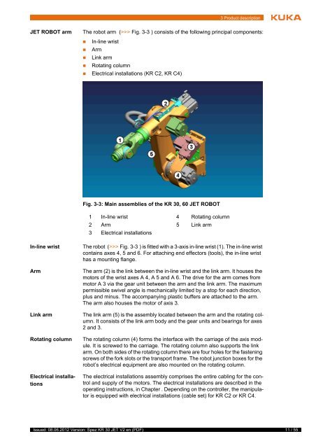
<strong>JET</strong> ROBOT arm The robot arm (>>> Fig. 3-3 ) consists of the following principal components:<br />
In-line wrist<br />
Arm<br />
Link arm<br />
Rotating column<br />
Electrical installations (<strong>KR</strong> C2, <strong>KR</strong> C4)<br />
In-line wrist The robot (>>> Fig. 3-3 ) is fitted with a 3-axis in-line wrist (1). The in-line wrist<br />
contains axes 4, 5 and 6. For attaching end effectors (tools), the in-line wrist<br />
has a mounting flange.<br />
Arm The arm (2) is the link between the in-line wrist and the link arm. It houses the<br />
motors of the wrist axes A 4, A 5 and A 6. The drive for the arm comes from<br />
motor A 3 via the gear unit between the arm and the link arm. The maximum<br />
permissible swivel angle is mechanically limited by a stop for each direction,<br />
plus and minus. The accompanying plastic buffers are attached to the arm.<br />
The arm also houses the motor of axis 3.<br />
Link arm The link arm (5) is the assembly located between the arm and the rotating column.<br />
It consists of the link arm body and the gear units and bearings for axes<br />
2 and 3.<br />
Rotating column The rotating column (4) forms the interface with the carriage of the axis module.<br />
It is screwed to the carriage. The rotating column also supports the link<br />
arm. On both sides of the rotating column there are four holes for the fastening<br />
screws of the fork slots or the transport frame. The robot junction boxes for the<br />
robot’s electrical equipment are also mounted on the rotating column.<br />
Electrical installations<br />
Fig. 3-3: Main assemblies of the <strong>KR</strong> <strong>30</strong>, 60 <strong>JET</strong> ROBOT<br />
1 In-line wrist 4 Rotating column<br />
2 Arm 5 Link arm<br />
3 Electrical installations<br />
The electrical installations assembly comprises the entire cabling for the control<br />
and supply of the motors. The electrical installations are described in the<br />
operating instructions, in Chapter . Depending on the controller, the manipulator<br />
is equipped with electrical installations (cable set) for <strong>KR</strong> C2 or <strong>KR</strong> C4.<br />
11 / 55