Networking
Networking
Networking

You also want an ePaper? Increase the reach of your titles
YUMPU automatically turns print PDFs into web optimized ePapers that Google loves.
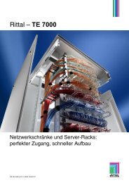
Rittal – IT Catalogue<br />
R
We have the modules to precisely solve your IT tasks<br />
SIMPLICITY AS THE HIGHEST LEVEL<br />
OF PERFECTION<br />
As little as possible, as much as necessary – find this balance, and you have perfection.<br />
Our IT technology is dynamic and innovative – but we also consciously design it to be<br />
simple. Simplicity is your advantage. In technical terms, this means reducing complex<br />
and complicated correlations to a minimum. In our relationship with you, we take care of<br />
everything so that you needn’t worry about a thing.<br />
Simply perfect, thanks to intelligent system diversity and an holistic approach –<br />
these are customer solutions from Rittal.<br />
Communication is the future.<br />
Rittal offers inspiring IT solutions<br />
from the outset.
CONTENTS<br />
Rittal IT catalogue<br />
<strong>Networking</strong> . . . . . . . . . . . . . . . . . . . . . . . . . 12<br />
Server racks . . . . . . . . . . . . . . . . . . . . . . . . 72<br />
Power . . . . . . . . . . . . . . . . . . . . . . . . . . . . . 92<br />
Cooling . . . . . . . . . . . . . . . . . . . . . . . . . . . 112<br />
Security . . . . . . . . . . . . . . . . . . . . . . . . . . . 152<br />
Monitoring & remote management . . . . . 186<br />
IT infrastructure/service . . . . . . . . . . . . . . 202<br />
Telecom/distributor racks . . . . . . . . . . . . . 220<br />
Yet more IT solutions . . . . . . . . . . . . . . . . 238<br />
System accessories . . . . . . . . . . . . . . . . . 252<br />
Engineering and consultancy . . . . . . . . . 400<br />
Innovations . . . . . . . . . . . . . . . . . . . . . . . . 422<br />
3
Curiosity creates new paths for us to follow.<br />
● Rittal’s permanent innovation achievements are the result<br />
of global dialogue with our customers.<br />
● Our own accredited laboratories guarantee quality and<br />
cost efficiency in accordance with ambitious international<br />
standards, leading to internationally recognised approvals<br />
for global use.<br />
4 Rittal IT catalogue
We give pioneering answers<br />
DETERMINATION IS THE ENGINE<br />
OF PROGRESS<br />
Fascinating future – we see this as much more than just a slogan. We are born to inno-<br />
vate. We live our passion, which is what makes us truly convincing. This is the only way<br />
for us to be credible, and to achieve lasting success with you.<br />
We realise the importance of continuously building on our outstanding position in order<br />
to rank among the technological leaders in a global market. Wireless, biometrics and<br />
energy-efficient protection are just some of the dynamic technologies we are pursuing<br />
with exceptional commitment and expertise. We are keen to be measured by these<br />
developments in future.<br />
International Rittal research teams are working for the future with clear objectives in mind:<br />
Exceptional benefits for the user, enhanced energy efficiency, and conservation of our<br />
natural resources.<br />
Wireless Energy efficiency Personal identification
We offer system integration – for industry and all sections of the company<br />
COMMUNICATION AS THE BASIS<br />
We live in an information society. Information and data are productivity factors.<br />
Every company and every individual is reliant on information. Those with better, faster<br />
information are able to secure a competitive lead. We ensure that modern IT technology<br />
has the best framework and meets your requirements to perfection.<br />
The Rittal system platforms are called rack, cooling, power, security and monitoring.<br />
Rittal solutions for the physical IT infrastructure are based on an holistic approach,<br />
combined with an exceptional determination to drive progress forwards at every oppor-<br />
tunity. Our philosophy has made us a much sought-after partner.<br />
Talk to us.<br />
Thoroughly modern, scalable and efficient<br />
system solutions – that’s Rittal.<br />
6 Rittal IT catalogue<br />
R
Rittal IT catalogue<br />
People are at the heart of all communications. They plan<br />
and organise, initiate and control. The IT infrastructure also<br />
has a decisive effect on his efficiency and success. Rittal<br />
offers holistic solutions which embrace all sections of the<br />
company, whatever the industry!<br />
Rack – power – cooling – security – monitoring for<br />
● Data centres<br />
● IT infrastructure<br />
● Data and network technology<br />
● Decentralised computer systems<br />
● Building distribution<br />
● Indoor and outdoor communication<br />
● Industrial Ethernet<br />
7
Expertise, customer proximity, quality, deliverability,<br />
product diversity and global service – these are Rittal’s<br />
great strengths.<br />
Around 10,000 Rittal employees around the globe with production<br />
and logistical expertise are working on customised<br />
developments and in modification centres, at:<br />
● 19 production sites<br />
● 60 subsidiaries<br />
● 70 agencies and<br />
● 150 distribution and logistics centres.<br />
8 Rittal IT catalogue
We hold face-to-face meetings . . . at countless national and international trade fairs . . . and at 300 Rittal sites – worldwide.<br />
Rittal IT catalogue<br />
We are there for you, whenever and wherever you need us<br />
GLOBAL PROXIMITY<br />
To offer customer proximity, you need to be mobile. The desire to keep moving is in<br />
our blood. We are totally and globally customer-oriented. This is a large part of our<br />
attraction, which translates into a genuine added value for you.<br />
We are there for you. We are local. Anywhere in the world. However, for us, customer<br />
proximity is not just geographical; it is also a question of seeking out face-to-face<br />
meetings wherever possible. Because for us, a meeting is the starting point of our<br />
“customer-based” developments, in the most literal sense of the word. We show you<br />
the most innovative, most cost-efficient path.<br />
Requirement analysis, planning, development, prototype construction, modifica-<br />
tions, tests, production, assembly, service and support – that’s Rittal service.<br />
9
Extensive technical expertise, well-established structures, and a complete<br />
service chain<br />
EFFICIENCY AS STANDARD<br />
Efficiency is a combination of efficacy plus cost-effectiveness. It sounds easy, and it is,<br />
but only provided all parts work together with optimum interaction between individual<br />
modules. Rittal sets new standards: TBU – Total Benefit of Usership – considers all the<br />
benefits arising from the use of a product. In order to achieve the aspired levels of<br />
availability and reliability (efficacy), the sum total of all purchase and operating costs<br />
(cost-efficiency) must be reduced to a minimum, a process that we have perfected to<br />
a fine art. Energy efficiency comes as standard with Rittal, particularly when it is a<br />
question of supplying complete solutions for optimum reliability and maximum avail-<br />
ability with an appropriate level of investment. This demands integrated solutions, such<br />
as those supplied by Rittal worldwide on every scale. Furthermore, Rittal is distinguished<br />
by the innovative strengths we derive from our relentless curiosity and fascination.<br />
Tailor-made systems, no over-sizing, no unnecessary fixed costs, and where<br />
necessary, simple expansion with the system operational – this is the<br />
“pay-as-you-go” concept from Rittal.<br />
RimatriX5 IT infrastructures Business continuity management Physical IT security
Rittal IT catalogue<br />
Rittal International, compromising of – Rittal – Litcos – Lampertz –,<br />
offers its customers holistic IT infrastructures from a single source.<br />
High standards of reliability and availability are achieved costeffectively,<br />
with perfect results.<br />
● With RimatriX5, Rittal offers a comprehensive range of services<br />
and a full choice of modules for your rack-based IT infrastructure.<br />
● Litcos: Analytical advice and holistic planning of data centre<br />
structures.<br />
● Lampertz: Modular IT security rooms (room-within-a-room concept)<br />
and IT security cabinets, with an emphasis on fire and theft<br />
protection.<br />
11
A complete network of<br />
enclosure solutions<br />
Rittal produces innovative, cost-effective solutions for all<br />
types of IT enclosure systems. Compact, stylish, pre-con-<br />
figured, and in a wide range of sizes. Moreover, Rittal has<br />
a range of system accessories to suit every enclosure, and<br />
therefore offers a suitable enclosure solution for every app-<br />
lication. Rittal networking always means accessing the<br />
holistic solution; the integrative Rittal system. From power<br />
management, to security and monitoring, through to cooling.<br />
Rittal enclosure solutions are far more than just the width,<br />
height and depth of the enclosure. Instead, they are a<br />
complementary network of versatile ideas for adapting to<br />
practical requirements and the needs of the future.<br />
TE 7000 network enclosures<br />
Two depth-variable 482.6 mm (19″)<br />
mounting levels provide a solid framework<br />
(load capacity 400 kg) for all<br />
fixed and patching tasks.<br />
In keeping with the principle “as little<br />
as possible, as much as necessary”,<br />
this rack does not require an<br />
enclosure frame. Benefits: Optimum<br />
accessibility and simple assembly.<br />
A practical, cost-effective solution for<br />
distributors in office environments.<br />
Rittal IT catalogue/<strong>Networking</strong><br />
TS 8 network enclosures<br />
A diversity of applications and variability,<br />
both as a distributor and in combination<br />
with installed servers.<br />
Regardless of how demanding your<br />
requirements may be, unrestricted<br />
mounting diversity and a comprehensive<br />
range of system accessories<br />
means that a solution with TS 8 always<br />
offers excellent value for money.<br />
Reliability and availability may be<br />
tailored precisely to requirements,<br />
using modular lock, climate control<br />
and monitoring solutions.<br />
<strong>Networking</strong> from page 14<br />
System comparison of enclosures....................................................14<br />
System comparison of wall-mounted enclosures .............................16<br />
Installation examples ........................................................................18<br />
Network enclosures, based on Rittal TE 7000..................................26<br />
Network enclosures, based on Rittal TS 8........................................32<br />
Network enclosures, based on Rittal flexRack(i) ..............................48<br />
RNC enclosures................................................................................53<br />
Accessories for RNC enclosures......................................................55<br />
Wall-mounted enclosures, based on Rittal QuickBox ......................57<br />
Wall-mounted enclosures, based on Rittal AE .................................60<br />
Wall mounted enclosure, based on Rittal AE, with pull-out frame....61<br />
Wall-mounted enclosures, based on Rittal EL, 3-part ......................62<br />
Wall-mounted enclosures, based on Rittal EL, 2-part ......................66<br />
EMC wall-mounted enclosure, based on Rittal EL, 3-part................67<br />
Small fibre-optic distributors.............................................................68<br />
Small fibre-optic distributors, based on Rittal AE .............................69<br />
Fibre-optic marshalling enclosure ....................................................70<br />
Small fibre-optic distributor, polycarbonate .....................................71<br />
Wall-mounted enclosures<br />
The Rittal wall-mounted range has something<br />
for everyone.<br />
Tailored to IT distribution applications,<br />
they are distinguished by optimum<br />
accessibility, high production<br />
quality, and a comprehensive range of<br />
system accessories.<br />
13<br />
<strong>Networking</strong>
<strong>Networking</strong><br />
<strong>Networking</strong><br />
System comparison of enclosures<br />
Plan with the best network enclosure for your require-<br />
ments!<br />
Customers’ requirements of IT enclosures can be<br />
extremely varied. With this in mind, Rittal offers three<br />
different system platforms with outstanding design<br />
features for a variety of applications.<br />
Rittal system comparison TE 7000 TS 8 FR(i)<br />
One platform for all requirements<br />
in the IT market<br />
Load capacity<br />
up to 400/700 kg <br />
up to 1000 kg<br />
Baying<br />
<br />
Side to side <br />
In all levels <br />
Dismantling<br />
Climate control<br />
<br />
Fans <br />
Cooling unit <br />
Air/water<br />
heat exchanger<br />
<br />
CPU liquid cooling<br />
Cabling<br />
<br />
Cable space <br />
Cable management<br />
Lock system<br />
<br />
2-point <br />
4-point<br />
Security<br />
<br />
Access control <br />
Thermal management<br />
Interior installation<br />
<br />
Depth-variable <br />
Partial installation <br />
2-level principle <br />
Aesthetics<br />
Standards<br />
<br />
IEC 60 297-1-2 <br />
Protection<br />
categories<br />
Note:<br />
IP 20<br />
IP 40<br />
IP 55<br />
<br />
<br />
<br />
<br />
<br />
The more the greater the compatibility.<br />
TE 7000<br />
TE 7000 – Top efficiency, the global IT rack<br />
Ready to use for network distribution. As little as possible,<br />
as much as necessary – the rack for rational, costeffective<br />
cabling.<br />
● At its core is the robust frame comprising two<br />
482.6 mm (19″) mounting levels.<br />
● Two-point locking rod, optionally with Ergoform-S<br />
handle system.<br />
● System accessories ensure fast, versatile configuration.<br />
Network enclosures TE 7000, see page 26.<br />
14 Rittal IT catalogue/<strong>Networking</strong>
Rittal TS 8 Rittal flexRack(i)<br />
TS 8 – the Top enclosure system<br />
This offers diversity and protection for your network,<br />
based on the ingenious rack profile. With two levels, it<br />
facilitates unlimited interior installation.<br />
● Suitable for one or two 482.6 mm (19″) mounting<br />
levels, partial or full installation.<br />
● The ingenious symmetry concept of the frame offers<br />
baying on all sides.<br />
● A high level of security, thanks to lock systems with<br />
a comfort handle and 4-point locking.<br />
● Perfect integration of climate control components.<br />
● Protection category up to IP 55.<br />
Network enclosures TS 8, see page 32.<br />
Rittal IT catalogue/<strong>Networking</strong><br />
<strong>Networking</strong><br />
System comparison of enclosures<br />
flexRack(i) – The high-end designer rack<br />
A stylish design, a high degree of stability, plus futuristic<br />
technology – with the hollow aluminium section.<br />
● Cables may be routed and system accessories<br />
integrated within the hollow chamber of the frame<br />
section.<br />
● Power management integrated directly into the frame<br />
section. Three-phase infeed using the plug & play<br />
system, with no loss of enclosure volume.<br />
Network enclosures flexRack(i), see page 48.<br />
15<br />
<strong>Networking</strong>
<strong>Networking</strong><br />
<strong>Networking</strong><br />
System comparison of wall-mounted enclosures<br />
RNC enclosure<br />
RNC universal enclosure<br />
Prepared for the installation of<br />
1 /219″ components. 10″ components<br />
may also be installed by<br />
using an adaptor. 482.6 mm<br />
(19″) variant for vertical populati<br />
The universal enclosure, vertical<br />
for 19″ installation, horizontal for<br />
1 /219″ or 10″ installation.<br />
Cut-outs in the mounting<br />
bracket for access to the rear<br />
of the patch panels or active<br />
components.<br />
The configuration of decentralised network units is extremely<br />
important for small and medium-sized companies. Rittal has<br />
high-quality solutions to meet virtually every requirement of a<br />
growing network.<br />
Wall-mounted enclosures, based on Rittal QuickBox<br />
Side panels with integral vent<br />
slots.<br />
Bayed for 482.6 mm (19″) configuration,<br />
vertical and horizontal.<br />
Slide rails to support heavy<br />
assemblies.<br />
The floor-standing enclosure<br />
may also be used as a wallmounted<br />
enclosure with additional<br />
support brackets.<br />
Passive ventilation<br />
To accommodate a prepared<br />
fan, cable entry with brush strip.<br />
Vent slots for passive ventilation.<br />
16 Rittal IT catalogue/<strong>Networking</strong>
Whether fibre-optic or copper distributors, 1 /219″ or 19″ enclo-<br />
sures, high protection category or passively vented wall-mounted<br />
enclosures, the IT wall-mounted distributor range covers every<br />
conceivable requirement and is available off the shelf.<br />
Wall-mounted and distribution enclosures<br />
Rittal IT catalogue/<strong>Networking</strong><br />
Wall-mounted enclosure<br />
based on AE with pull-out frame<br />
or depth-adjustable 482.6 mm<br />
(19″) level.<br />
Fibre-optic marshalling<br />
enclosure<br />
Two access areas:<br />
1. For splicing cassette mounting<br />
2. For the patching chamber.<br />
Optimum accessibility thanks to<br />
3-part or 2-part vertically hinged<br />
configuration.<br />
<strong>Networking</strong><br />
System comparison of wall-mounted enclosures<br />
Small fibre-optic distributor<br />
As a corridor and intermediate<br />
distributor of fibre-optic cables.<br />
Small fibre-optic distributors,<br />
polycarbonate, for extreme<br />
conditions with a high protection<br />
category of IP 66 to<br />
EN 60 529/10.91.<br />
Wall-mounted enclosures, based on Rittal EL, 3-part/2-part<br />
Equipped with Mini comfort handle<br />
(3 – 15 U), comfort handle<br />
(18 and 21 U) and replaceable<br />
cable gland plates.<br />
Small fibre-optic distributor,<br />
based on AE<br />
The ideal enclosure for breakout<br />
applications.<br />
2-part enclosure with swing<br />
frame. Facility for installing subracks<br />
and electronic components.<br />
17<br />
<strong>Networking</strong>
TE 7000<br />
Network enclosures<br />
Rittal IT catalogue/<strong>Networking</strong><br />
1<br />
2<br />
3<br />
4<br />
This is what TE Top Efficiency looks like!<br />
The rack for rational, cost-effective cabling, ready to use in<br />
network distribution:<br />
At its core is the robust frame comprising two 482.6 mm (19″)<br />
attachment levels. Add to this a host of useful accessories<br />
from Rittal’s comprehensive modular system, and you will<br />
arrive at the precise configuration which meets your require-<br />
ments to perfection, quickly and cost effectively.<br />
5<br />
Example: System accessories for perfect configuration of a TE 7000 network enclosure<br />
Use these examples to help you. Socket strips, lights, cable management<br />
devices and other system accessories are<br />
all available from Rittal, in a wide range of<br />
variants suitable for different applications.<br />
7<br />
1 Light, 1 U<br />
2 Fan unit, active<br />
3 Fibre-optic cable management panel,<br />
1U<br />
4 Cable routing bar, 1 U<br />
5 Cable routing bar, 4 U<br />
Note:<br />
TE 7000 network enclosures, see page 26.<br />
Parts list with model numbers for this example,<br />
see page 22.<br />
6<br />
8<br />
9<br />
14<br />
15<br />
10<br />
11<br />
6 Socket strip TE, 8-way<br />
7 Cable management panel, 1 U<br />
8 Cable gland panel<br />
9 Cable routing bar, cranked, 4 U<br />
10 Component shelf, static installation<br />
11 Distributor clip, small<br />
12 Earth rail<br />
13 Distributor clip, large<br />
14 Drawer, 2 U<br />
15 UPS, single-phase<br />
13<br />
12<br />
19<br />
<strong>Networking</strong>
TS 8<br />
Network enclosures<br />
3<br />
4<br />
Rittal IT catalogue/<strong>Networking</strong><br />
1<br />
6<br />
2<br />
Customised from the modular system – the fast route to a<br />
Top solution! Stylish glazed door, maximum installation varia-<br />
bility, and exceptional security thanks to the lock system and<br />
protection category (up to IP 55) – these are the distinguishing<br />
features of the TS 8 Top enclosure system. The symmetrical<br />
layout and two-level principle of the TS 8 section facilitate opti-<br />
mum space utilisation in every level.<br />
At the same time, the TS 8 is extremely resilient (load capacity<br />
up to 1000 kg) and offers various options for system integra-<br />
tion (power supply, climate control, access protection and<br />
monitoring).<br />
5<br />
Example: System accessories for perfect configuration of a TS 8 network enclosure<br />
Rittal system accessories are available 1 System light (Linestra)<br />
in many different variants, tailored to the<br />
intended application. 482.6 mm (19″)<br />
2 Fan tray<br />
partial configuration and the use of com- 3 Power cable, light<br />
ponent shelves across the entire enclosure<br />
width are likewise easily achieved.<br />
4 Cable routing bar, cranked, 4 U<br />
Use these examples to help you.<br />
5 C rails<br />
6 Fibre-optic cable management panel,<br />
1U<br />
7 Cable gland panel<br />
8 Socket strip, 5-way with overvoltage<br />
protection and RFI suppressor filter<br />
10<br />
12<br />
Note:<br />
TS 8 network enclosures, see page 32.<br />
Parts list with model numbers for this example,<br />
see page 23.<br />
9<br />
11<br />
7<br />
8<br />
15<br />
18<br />
13<br />
14<br />
9 Socket strip, 7-way<br />
10 Component shelf, 482.6 mm (19″)<br />
installation<br />
11 Telescopic slides for component shelf<br />
12 Cable management panel, 1 U<br />
13 Cable routing bar, 4 U<br />
14 Cable management panel, 1 U<br />
15 Drawer, 2 U<br />
16 Blanking panel, 482.6 mm (19″), 2 U<br />
17 Distributor clip, large<br />
18 UPS, single-phase<br />
16<br />
17<br />
21<br />
<strong>Networking</strong>
<strong>Networking</strong><br />
<strong>Networking</strong><br />
Parts list for the configuration example TE 7000<br />
No. Name Packs of Model No. Page<br />
TE 7000 network enclosure, pre-configured<br />
W = 800 mm, H = 2000 mm, D = 800 mm<br />
Accessories<br />
1 DK 7000.850 26<br />
1 Light, 1 U 1 DK 7109.200 335<br />
2 Fan unit, active 1 DK 7000.670 128<br />
3 Fibre-optic cable management panel, 1 U 1 DK 7256.035 363<br />
4 Cable routing bar, 1 U 10 DK 7111.212 360<br />
5 Cable routing bar, 4 U 4 DK 7111.222 360<br />
6 Socket strip TE, 8-way 1 DK 7000.630 331<br />
7 Cable management panel, 1 U 1 DK 7257.035 361<br />
8 Cable gland panel 1 DK 7140.535 363<br />
9 Cable routing bar, cranked, 4 U 4 DK 7111.220 360<br />
10 Component shelf, static installation 1 DK 7000.620 320<br />
11 Distributor clip, small 4 DK 7111.250 360<br />
12 Earth rail, vertical 1 DK 7113.000 338<br />
13 Distributor clip, large 4 DK 7111.252 360<br />
14 Drawer, 2 U 1 DK 7282.035 385<br />
15 UPS, single-phase 1 DK 7857.430 433<br />
Optional accessories<br />
A Power: Single-phase UPS 433<br />
B Security: Monitoring system CMC-TC 158<br />
C Cooling: Fan systems 123<br />
D Lock systems 282<br />
E Lock cylinder 282<br />
F Cable routing, cable routing bars 360<br />
A<br />
Single-phase UPS<br />
B Monitoring system CMC-TC C<br />
Fan systems<br />
D Lock systems<br />
E Lock cylinder<br />
F Cable bars<br />
22 Rittal IT catalogue/<strong>Networking</strong>
Rittal IT catalogue/<strong>Networking</strong><br />
<strong>Networking</strong><br />
Parts list for the configuration example TS 8<br />
No. Name Packs of Model No. Page<br />
TS 8 network enclosure, pre-configured<br />
W = 800 mm, H = 2000 mm, D = 800 mm<br />
Accessories<br />
DK 7930.200 32<br />
1 System light (Linestra) 1 PS 4103.350 335<br />
2 Fan tray 1 DK 7988.035 127<br />
3<br />
4<br />
5<br />
6<br />
7<br />
8<br />
9<br />
10<br />
11<br />
12<br />
13<br />
14<br />
15<br />
16<br />
Power cable, light 5 PS 4315.100 336<br />
Cable routing bar, cranked, 4 U 4 DK 7111.220 360<br />
C rails DK 7828.080 307<br />
Fibre-optic cable management panel, 1 U 1 DK 7256.035 363<br />
Cable gland panel 1 DK 7140.535 363<br />
Socket strip, 5-way with overvoltage protection and interference<br />
suppressor filter<br />
1 DK 7240.230 328<br />
Socket strip, 7-way 1 DK 7240.210 328<br />
Component shelf, 482.6 mm (19″) configuration 1 DK 7145.035 319<br />
Telescopic slides for component shelf 2 DK 7081.000 326<br />
Cable management panel, 1 U 1 DK 7257.035 361<br />
Cable routing bar, 4 U 4 DK 7111.222 360<br />
Cable management panel, 1 U 1 DK 7159.035 361<br />
Drawer, 2 U 1 DK 7282.035 385<br />
Blanking panel, 482.6 mm (19″), 2 U 2 DK 7152.035 392<br />
17 Distributor clip, large 4 DK 7111.252 360<br />
18 UPS, single-phase 1 DK 7857.430 433<br />
Optional accessories<br />
A Voltage supply: Energy-Box 332<br />
B Security: Monitoring system CMC-TC 158<br />
C Cable management 350<br />
D 19″ installation system 364<br />
E Doors 277<br />
F Interior installation 295<br />
A Energy Box<br />
B<br />
Monitoring system CMC-TC<br />
Cable management<br />
D 19″ installation system<br />
E Designer glazed door<br />
F Interior installation<br />
C<br />
23<br />
<strong>Networking</strong>
Wall-mounted enclosure, 3-part<br />
1<br />
2<br />
3<br />
2<br />
1<br />
Shunting ring with cable shunting ring,<br />
polyamide (DK 7159.035)<br />
2 outlet filters (SK 3322.207),<br />
included in supply<br />
Junction box (DK 7280.035)<br />
A high protection category and optimum accessibility thanks to a 3-part, vertically hinged configuration – the EL<br />
wall-mounted enclosure with 482.6 mm (19″) mounting angles is ideally suited for small, decentralised networks,<br />
as a corridor distributor, or for all “Ethernet goes factory” applications. The EL enclosure proves that a protection<br />
category of up to IP 55 is no barrier to an attractive design, making Note:<br />
Wall-mounted enclosure, 3-part,<br />
it particularly suitable for use even in tough industrial environments. see page 62.<br />
3<br />
System accessories for pre-configured wall-mounted enclosure, 3-part (DK 7715.735), W x H x D mm = 600 x 746 x 572.5, 15 U:<br />
Mini Comfort handle (DK 7705.120),<br />
included in the supply<br />
24 Rittal IT catalogue/<strong>Networking</strong><br />
4<br />
4 5 Socket strip, 7-way (DK 7240.210)<br />
6<br />
7<br />
6<br />
Component shelf 2 U, static installation<br />
(DK 7119.400)<br />
Earth rail with star earthing (DK 7113.000),<br />
included in the supply<br />
5<br />
7
QuickBox wall-mounted enclosure<br />
Rittal IT catalogue/<strong>Networking</strong><br />
2<br />
Installations that are accessible from all sides are extremely advantageous in day-to-day handling.<br />
The removable cover of the QuickBox complements this to perfection. Other consistent design<br />
features, such as large cut-outs in the mounting<br />
brackets, brush strips and vent slots, make the QuickBox<br />
a universal office distributor.<br />
1<br />
3<br />
System accessories for QuickBox wall-mounted enclosure (DK 7502.046), W x H x D mm = 600 x 762 x 600, 15 U:<br />
1 Mounting angles, 482.6 mm (19″)<br />
4 Socket strip, 7-way (DK 7240.210)<br />
6<br />
Brush strip top and bottom.<br />
(DK 7502.204)<br />
5 Component shelf 2 U, static installation<br />
2 Cable panel with cable shunting ring,<br />
polyamide (DK 7255.035)<br />
(DK 7119.400)<br />
3 Junction box (DK 7280.035)<br />
5<br />
4<br />
Note:<br />
QuickBox wall-mounted enclosures,<br />
see page 57.<br />
6<br />
25
<strong>Networking</strong><br />
<strong>Networking</strong><br />
Network enclosures TE 7000, pre-configured<br />
Benefits:<br />
● 19″ mounting angles front and<br />
rear always included<br />
● No frame structure,<br />
optimum accessibility<br />
● Load capacity up to 400 kg<br />
● Pre-configured solution,<br />
including extensive accessory<br />
kit.<br />
Material:<br />
Sheet steel<br />
Surface finish:<br />
Mounting frame:<br />
Electrophoretic dipcoat-primed<br />
Enclosure panels:<br />
Powder-coated, RAL 7035.<br />
T1<br />
B<br />
26 Rittal IT catalogue/<strong>Networking</strong><br />
H<br />
T1<br />
B<br />
H<br />
Pre-configured Pre-configured Page<br />
U 24 42<br />
Width (B) mm 1) 800 800<br />
Height (H) mm 1) 1200 2000<br />
Depth (T1) mm 1) 800 800<br />
Distance between 482.6 mm (19″) levels in its delivered state mm 495 495<br />
Model No. TE 7000.840 7000.850<br />
Model No. TE as bayed enclosure without side panels, including baying kit – 7000.852<br />
Supply includes<br />
Self-supporting 482.6 mm (19″) frame structure, depth-variable at the front and rear <br />
Glazed door at the front, including 130° hinge, two-point locking rod, recessed handle and<br />
security lock 3524 E<br />
<br />
Sheet steel door at the rear, including 130° hinge, two-point locking rod, recessed handle and<br />
security lock 3524 E<br />
<br />
Pluggable weight-reduced side panels, including security lock 3524 E (7000.850 only)<br />
Base frame with maximum cut-out (for optional population with modular panels, solid,<br />
with passive ventilation or for cable entry)<br />
<br />
Roof plate including brush strip for cable entry and concealed cut-out for population via the active fan plate <br />
4 levelling feet (including base/plinth adaptor) supplied loose <br />
Spacers, 20 mm, supplied loose to raise the roof <br />
Base/plinth 100 mm, vented <br />
Tested frame earthing to EN 60 950, fitted<br />
Accessory kit<br />
<br />
4 C rails, for cable clamping in the enclosure depth via cable clamps, supplied loose <br />
10 cable shunting rings made of plastic, 105 x 70 mm, supplied loose <br />
50 captive nuts, M6, conductive, supplied loose <br />
50 multi-tooth screws, M6, with plastic washers, supplied loose<br />
Premium accessories TE, for direct mounting in the delivered state<br />
<br />
Ergoform S handle for semi-cylinder, to exchange for the existing lock 2435.000 2435.000 284<br />
Fan module, with 2 fans and thermostat, pre-wired ready for connection 7000.670 7000.670 128<br />
Slide rail for TE, for attachment between the 482.6 mm (19″) mounting frames, length 424 mm 7963.410 7963.410 384<br />
19″ component shelf for static installation, for direct screw-fastening without an installation kit, 412 mm deep,<br />
load capacity 30 kg, static<br />
7000.620 7000.620 320<br />
Punched section with mounting flange 17 x 73 mm, for mounting installation components, attached in the<br />
enclosure depth between the 482.6 mm (19″) mounting frames<br />
8612.040 8612.040 299<br />
C rail, for cable clamping in the enclosure depth via cable clamps <br />
C rail, for cable clamping in the enclosure width via cable clamps,<br />
on the 482.6 mm (19″) mounting frame at the rear<br />
7828.060 7828.060 307<br />
Cable clamp rail, depth-variable 325 – 575 mm, for cable attachment in the enclosure depth via cable ties 7858.160 7858.160 354<br />
Cable clamp rail for cable attachment in the enclosure depth using cable ties,<br />
on the 482.6 mm (19″) mounting frame at the rear<br />
7828.062 7828.062 354<br />
Earthing kit for TE <br />
Economy socket strip, 8-way for earthing-pin plugs 7000.630 7000.630 331<br />
Included with the supply. 1) All sizes are nominal dimensions. For absolute dimensions, please refer to the detailed drawing on the Internet.
Benefits:<br />
● Accessories configured to<br />
order for fast installation<br />
● No frame structure, optimum<br />
accessibility<br />
● Load capacity up to 400 kg<br />
Material:<br />
Sheet steel<br />
495 mm – This is the distance<br />
between the two 482.6 mm<br />
(19″) levels for all enclosure<br />
formats in their delivered state.<br />
Complies with TS 8 nominal<br />
depth 400 mm, inner level.<br />
Pitch spacing 50 mm.<br />
The distance between the two<br />
482.6 mm (19″) levels may be<br />
varied in increments of 50 mm<br />
(445 to 695 mm).<br />
Distance from door:<br />
52.5 mm for depth 600<br />
152.5 mm for depth 800<br />
The mounting distance in a<br />
rear mounting frame, horizontal,<br />
corresponds to the frame<br />
mounting dimensions of a<br />
600 mm wide TS 8 (inner level,<br />
512 mm).<br />
Rittal IT catalogue/<strong>Networking</strong><br />
Surface finish:<br />
Mounting frame:<br />
Electrophoretic dipcoat-primed<br />
Enclosure panels:<br />
Powder-coated, RAL 7035/<br />
RAL 9005<br />
Supply includes:<br />
Self-supporting 482.6 mm (19″)<br />
frame structure,<br />
E = A – 120 mm<br />
Accessories Page 252 Monitoring Page 187 Climate control Page 113<br />
<strong>Networking</strong><br />
Network enclosures, based on Rittal TE 7000, width 600<br />
Choose the distance between<br />
levels completely freely via the<br />
slot fastening. All key mounting<br />
components – punched sections<br />
with mounting flanges, installation<br />
kits, slide rails, component<br />
shelves – are also available in a<br />
depth-variable version.<br />
600<br />
600<br />
A<br />
D<br />
800<br />
600<br />
A<br />
glazed door at the front,<br />
two-point locking rod, recessed<br />
handle and security lock 3524 E,<br />
sheet steel door at rear,<br />
two-point locking rod, recessed<br />
handle and security lock<br />
3524 E, plug-in side panels<br />
with security lock 3524 E,<br />
base frame with maximum<br />
German registered design<br />
no. 403 07 489<br />
D<br />
C<br />
E<br />
T<br />
B<br />
A<br />
H<br />
HE = U<br />
HE<br />
19˝<br />
cut-out (for optional population<br />
with module plates), roof plate<br />
for cable entry with concealed<br />
cut-out for fan, levelling feet,<br />
spacers for raising the cover<br />
plate.<br />
Detailed drawing,<br />
available on the Internet.<br />
U 11 11 24 24 42 42 47 47<br />
Width (B) mm1) 600 600 600 600 600 600 600 600<br />
Height (H) mm 1) 600 600 1200 1200 2000 2000 2200 2200<br />
Depth (T1) mm 1) 600 800 600 800 600 800 600 800<br />
Distance between 482.6 mm (19″) levels<br />
as delivered A mm<br />
495 495 495 495 495 495 495 495<br />
Model No. TE, RAL 7035 7000.390 7000.410 7000.430 7000.440 7000.500 7000.510 7000.560 7000.570<br />
Model No. TE as a bayed enclosure<br />
without side panels, incl. baying kit, RAL 7035<br />
– – – – 7000.502 – 7000.562 –<br />
Model No. TE including side panels, RAL 9005 – – – – 7000.505 2) 7000.515 2) – –<br />
1) All sizes are nominal dimensions. For absolute dimensions, refer to detailed drawings on the Internet. 2) Delivery times on request.<br />
A<br />
B<br />
C<br />
D<br />
B<br />
D<br />
A<br />
A<br />
= Defined mounting<br />
distance for Premium<br />
accessories, see below.<br />
27<br />
<strong>Networking</strong>
<strong>Networking</strong><br />
<strong>Networking</strong><br />
Network enclosures, based on Rittal TE 7000, width 600<br />
U 11 11 24 24 Page<br />
Width (B) mm 1) 600 600 600 600<br />
Height (H) mm 1) 600 600 1200 1200<br />
Depth (T1) mm 1) 600 800 600 800<br />
Distance between 482.6 mm (19″) levels in its delivered state A mm 495 495 495 495<br />
Model No. TE, RAL 7035 7000.390 7000.410 7000.430 7000.440<br />
Model No. TE as a bayed enclosure without side panels,<br />
incl. baying kit, RAL 7035<br />
– – – –<br />
Model No. TE including side panels, RAL 9005<br />
Doors<br />
– – – –<br />
Glazed front door/sheet steel rear door <br />
Sheet steel front door/sheet steel rear door on request on request on request on request<br />
Ergoform-S handle for semi-cylinder,<br />
in exchange for the existing lock<br />
Side panel<br />
2435.000 2435.000 2435.000 2435.000 284<br />
Side panel, plug-type,<br />
including security lock 3524 E<br />
<br />
Baying kit<br />
Roof<br />
7000.640 7000.640 7000.640 7000.640 276<br />
Roof plate with brush strip for cable entry,<br />
prepared to accommodate an active fan unit<br />
<br />
Fan unit, 2 fans (max. 3) including thermostat 7000.670 7000.670 7000.670 7000.670 128<br />
Fan expansion kit 7980.000 7980.000 7980.000 7980.000 127<br />
Spacers 20 mm to raise the cover plate above<br />
the fan cut-out<br />
Base/plinth<br />
<br />
Roof frame with maximum cut-out for individual population<br />
with module plates, levelling feet M10<br />
<br />
Module plate variants for individual population from page 264 from page 264 from page 264 from page 264<br />
Base/plinth components solid, front and rear 8601.605 8601.605 8601.605 8601.605 255<br />
Base/plinth components, vented, front and rear 7825.601 7825.601 7825.601 7825.601 255<br />
Base/plinth trim, side 8601.065 8601.085 8601.065 8601.085 255<br />
Base/plinth adaptor for levelling feet M12 8800.220 8800.220 8800.220 8800.220 262<br />
Levelling feet M12 4612.000 4612.000 4612.000 4612.000 260<br />
Base/plinth installation accessories<br />
Interior installation/Premium accessories<br />
from page 254 from page 254 from page 254 from page 254<br />
482.6 mm (19″) mounting frames front and rear<br />
Punched section with mounting flange 17 x 73 mm, for mounting<br />
<br />
installation components, attached in the enclosure depth between<br />
the 482.6 mm (19″) mounting frames<br />
8612.040 8612.040 8612.040 8612.040 299<br />
Cable clamp rail, depth variable 325 – 575 mm,<br />
for cable attachment in the enclosure depth using cable ties<br />
7858.160 7858.160 7858.160 7858.160 354<br />
Cable clamp rail, for cable attachment in the enclosure width via<br />
cable ties, on the 482.6 mm (19″) mounting frame at the rear<br />
7828.062 7828.062 7828.062 7828.062 354<br />
C rail, for cable clamping in the enclosure depth via cable clamps 7828.040 7828.040 7828.040 7828.040 307<br />
C rail, for cable clamping in the enclosure width via cable clamps,<br />
on the 482.6 mm (19″) mounting frame at the rear<br />
7828.060 7828.060 7828.060 7828.060 307<br />
Earthing kit for TE 7000.675 7000.675 7000.675 7000.675 339<br />
TE socket strip, 8-way with earthing-pin plug 7000.630 7000.630 7000.630 7000.630 331<br />
Power accessories from page 328 from page 328 from page 328 from page 328<br />
Slide rail for TE, for attachment between the 482.6 mm (19″)<br />
mounting frames, length 424 mm<br />
482.6 mm (19″) component shelf for static installation,<br />
7963.410 7963.410 7963.410 7963.410 384<br />
for direct screw-fastening wtihout installation kit, 412 mm deep,<br />
load capacity 30 kg, static<br />
7000.620 7000.620 7000.620 7000.620 320<br />
Cable management from page 341 from page 341 from page 341 from page 341<br />
CMC-TC monitoring system<br />
Included with the supply.<br />
from page 158 from page 158 from page 158 from page 158<br />
1) All sizes are nominal dimensions. For absolute dimensions, please refer to the detailed drawing on the Internet.<br />
Accessories Page 252 Monitoring Page 187 Climate control Page 113<br />
28 Rittal IT catalogue/<strong>Networking</strong>
Rittal IT catalogue/<strong>Networking</strong><br />
<strong>Networking</strong><br />
Network enclosures, based on Rittal TE 7000, width 600<br />
U 42 42 47 47 Page<br />
Width (B) mm 1) 600 600 600 600<br />
Height (H) mm 1) 2000 2000 2200 2200<br />
Depth (T1) mm 1) 600 800 600 800<br />
Distance between 482.6 mm (19″) levels in its delivered state A mm 495 495 495 495<br />
Model No. TE, RAL 7035 7000.500 7000.510 7000.560 7000.570<br />
Model No. TE as a bayed enclosure without side panels,<br />
incl. baying kit, RAL 7035<br />
7000.502 – 7000.562 –<br />
Model No. TE including side panels, RAL 9005 7000.5052) 7000.5152) Doors<br />
– –<br />
Glazed front door/sheet steel rear door <br />
Sheet steel front door/sheet steel rear door on request on request on request on request<br />
Ergoform-S handle for semi-cylinder,<br />
in exchange for the existing lock<br />
Side panel<br />
2435.000 2435.000 2435.000 2435.000 284<br />
Side panel, plug-type,<br />
including security lock 3524 E<br />
(7000.500,<br />
7000.505 only)<br />
(7000.560 only) 266<br />
Baying kit<br />
Roof<br />
(7000.502 only) 7000.640 (7000.562 only) 7000.640 276<br />
Roof plate with brush strip for cable entry,<br />
prepared to accommodate an active fan unit<br />
<br />
Fan unit, 2 fans (max. 3) including thermostat 7000.670 7000.670 7000.670 7000.670 128<br />
Fan expansion kit 7980.000 7980.000 7980.000 7980.000 127<br />
Spacers 20 mm to raise the cover plate above the fan cut-out<br />
Base/plinth<br />
<br />
Base frame with max. cut-out for individual population with module<br />
plates, levelling feet M10<br />
<br />
Module plate variants for individual population from page 264 from page 264 from page 264 from page 264<br />
Base/plinth components solid, front and rear 8601.605 8601.605 8601.605 8601.605 255<br />
Base/plinth components, vented, front and rear 7825.601 7825.601 7825.601 7825.601 255<br />
Base/plinth trim, side 8601.065 8601.085 8601.065 8601.085 255<br />
Base/plinth adaptor for levelling feet M12 8800.220 8800.220 8800.220 8800.220 262<br />
Levelling feet M12 4612.000 4612.000 4612.000 4612.000 260<br />
Base/plinth installation accessories<br />
Interior installation/Premium accessories<br />
from page 254 from page 254 from page 254 from page 254<br />
482.6 mm (19″) mounting frames front and rear<br />
Punched section with mounting flange 17 x 73 mm, for mounting<br />
<br />
installation components, attached in the enclosure depth between<br />
the 482.6 mm (19″) mounting frames<br />
8612.040 8612.040 8612.040 8612.040 299<br />
Cable clamp rail, depth variable 325 – 575 mm,<br />
for cable attachment in the enclosure depth using cable ties<br />
7858.160 7858.160 7858.160 7858.160 354<br />
Cable clamp rail, for cable attachment in the enclosure width via<br />
cable ties, on the 482.6 mm (19″) mounting frame at the rear<br />
7828.062 7828.062 7828.062 7828.062 354<br />
C rail, for cable clamping in the enclosure depth via cable clamps 7828.040 7828.040 7828.040 7828.040 307<br />
C rail, for cable clamping in the enclosure width via cable clamps,<br />
on the 482.6 mm (19″) mounting frame at the rear<br />
7828.060 7828.060 7828.060 7828.060 307<br />
Earthing kit for TE 7000.675 7000.675 7000.675 7000.675 339<br />
TE socket strip, 8-way with earthing-pin plug 7000.630 7000.630 7000.630 7000.630 331<br />
Power accessories from page 328 from page 328 from page 328 from page 328<br />
Slide rail for TE, for attachment between the 482.6 mm (19″)<br />
mounting frames, length 424 mm<br />
482.6 mm (19″) component shelf for static installation,<br />
7963.410 7963.410 7963.410 7963.410 384<br />
for direct screw-fastening without an installation kit, 412 mm deep,<br />
load capacity 30 kg, static<br />
7000.620 7000.620 7000.620 7000.620 320<br />
Cable management from page 341 from page 341 from page 341 from page 341<br />
CMC-TC monitoring system<br />
Included with the supply.<br />
from page 158 from page 158 from page 158 from page 158<br />
1) All sizes are nominal dimensions. For absolute dimensions, please refer to the detailed drawing on the Internet.<br />
2) Delivery times available on request.<br />
Accessories Page 252 Monitoring Page 187 Climate control Page 113<br />
29<br />
<strong>Networking</strong>
<strong>Networking</strong><br />
<strong>Networking</strong><br />
Network enclosures, based on Rittal TE 7000, width 800<br />
Benefits:<br />
● Accessories configured to<br />
order for fast installation<br />
● No frame structure, optimum<br />
accessibility<br />
● Load capacity up to 400 kg<br />
Material:<br />
Sheet steel<br />
495 mm – This is the distance<br />
between the two 482.6 mm<br />
(19″) levels for all enclosure<br />
formats in their delivered state.<br />
Complies with TS 8 nominal<br />
depth 400 mm, inner level.<br />
Pitch spacing 50 mm.<br />
The distance between the two<br />
482.6 mm (19″) levels may be<br />
varied in increments of 50 mm<br />
(445 to 695 mm).<br />
Distance from door:<br />
52.5 mm for depth 600<br />
152.5 mm for depth 800<br />
The mounting distance in a<br />
rear mounting frame, horizontal,<br />
corresponds to the frame<br />
mounting dimensions of a<br />
600 mm wide TS 8 (inner level,<br />
512 mm).<br />
Surface finish:<br />
Mounting frame:<br />
Electrophoretic dipcoat-primed<br />
Enclosure panels:<br />
Powder-coated, RAL 7035/<br />
RAL 9005<br />
Supply includes:<br />
Self-supporting 482.6 mm (19″)<br />
frame structure,<br />
E = A – 120 mm<br />
Choose the distance between<br />
levels completely freely via the<br />
slot fastening. All key mounting<br />
components – punched sections<br />
with mounting flanges, installation<br />
kits, slide rails, component<br />
shelves – are also available in a<br />
depth-variable version.<br />
Accessories Page 252 Monitoring Page 187 Climate control Page 113<br />
600<br />
800<br />
A<br />
D<br />
800<br />
glazed door at the front,<br />
two-point locking rod, recessed<br />
handle and security lock 3524 E,<br />
sheet steel door at rear,<br />
two-point locking rod, recessed<br />
handle and security lock<br />
3524 E, plug-in side panels<br />
with security lock 3524 E,<br />
base frame with maximum<br />
30 Rittal IT catalogue/<strong>Networking</strong><br />
T1<br />
German registered design<br />
no. 403 07 489<br />
800<br />
A<br />
D<br />
C<br />
E<br />
A<br />
B<br />
H<br />
HE = U<br />
HE<br />
19˝<br />
cut-out (for optional population<br />
with module plates), roof plate<br />
for cable entry with concealed<br />
cut-out for fan, levelling feet,<br />
spacers for raising the cover<br />
plate.<br />
Detailed drawing,<br />
available on the Internet.<br />
U 24 24 42 42 47 47<br />
Width (B) mm1) 800 800 800 800 800 800<br />
Height (H) mm 1) 1200 1200 2000 2000 2200 2200<br />
Depth (T1) mm 1) 600 800 600 800 600 800<br />
Distance between 482.6 mm (19″) levels in its delivered state A mm 495 495 495 495 495 495<br />
Model No. TE, RAL 7035 7000.450 7000.460 7000.520 7000.530 7000.580 7000.590<br />
Model No. TE as bayed enclosure without side panels, including baying<br />
kit, RAL 7035<br />
– – – 7000.532 – 7000.592<br />
Model No. TE including side panels, RAL 9005 – – 7000.525 2) 7000.535 2) – –<br />
1) All sizes are nominal dimensions. For absolute dimensions, refer to detailed drawings on the Internet. 2) Delivery times on request.<br />
A<br />
B<br />
C<br />
D<br />
A<br />
= Defined mounting<br />
distance for Premium<br />
accessories, see below.<br />
B<br />
D<br />
A
Rittal IT catalogue/<strong>Networking</strong><br />
<strong>Networking</strong><br />
Network enclosures, based on Rittal TE 7000, width 800<br />
U 24 24 42 42 47 47 Page<br />
Width (B) mm 1) 800 800 800 800 800 800<br />
Height (H) mm 1) 1200 1200 2000 2000 2200 2200<br />
Depth (T1) mm 1) 600 800 600 800 600 800<br />
Distance between 482.6 mm (19″) levels in its delivered state A mm 495 495 495 495 495 495<br />
Model No. TE, RAL 7035 7000.450 7000.460 7000.520 7000.530 7000.580 7000.590<br />
Model No. TE as a bayed enclosure without side panels,<br />
incl. baying kit, RAL 7035<br />
– – – 7000.532 – 7000.592<br />
Model No. TE including side panels, RAL 9005 – – 7000.5252) 7000.5352) Doors<br />
– –<br />
Glazed front door/sheet steel rear door <br />
Sheet steel front door/sheet steel rear door on request on request on request on request on request on request<br />
Ergoform-S handle for semi-cylinder,<br />
in exchange for the existing lock<br />
Side panel<br />
2435.000 2435.000 2435.000 2435.000 2435.000 2435.000 284<br />
Side panel, plug-type,<br />
including security lock 3524 E<br />
<br />
( 7000.530,<br />
7000.535<br />
only)<br />
<br />
(7000.590<br />
only)<br />
Baying kit<br />
Roof<br />
7000.640 7000.640 7000.640<br />
(7000.532<br />
only)<br />
7000.640<br />
(7000.592<br />
only)<br />
276<br />
Roof plate with brush strip for cable entry,<br />
prepared to accommodate an active fan unit<br />
<br />
Fan unit, 2 fans (max. 3) including thermostat 7000.670 7000.670 7000.670 7000.670 7000.670 7000.670 128<br />
Fan expansion kit 7980.000 7980.000 7980.000 7980.000 7980.000 7980.000 127<br />
Spacers 20 mm to raise the cover plate above the fan cut-out<br />
Base/plinth<br />
<br />
Base frame with max. cut-out for individual population with module<br />
plates, levelling feet M10<br />
<br />
Module plate variants for individual population from p. 264 from p. 264 from p. 264 from p. 264 from p. 264 from p. 264<br />
Base/plinth components solid, front and rear 8601.805 8601.805 8601.805 8601.805 8601.805 8601.805 255<br />
Base/plinth components, vented, front and rear 7825.801 7825.801 7825.801 7825.801 7825.801 7825.801 255<br />
Base/plinth trim, side 8601.065 8601.085 8601.065 8601.085 8601.065 8601.085 255<br />
Base/plinth adaptor for levelling feet M12 8800.220 8800.220 8800.220 8800.220 8800.220 8800.220 262<br />
Levelling feet M12<br />
Interior installation/Premium accessories<br />
4612.000 4612.000 4612.000 4612.000 4612.000 4612.000 260<br />
482.6 mm (19″) mounting frames front and rear<br />
Punched section with mounting flange 17 x 73 mm, for mounting<br />
<br />
installation components, attached in the enclosure depth between<br />
the 482.6 mm (19″) mounting frames<br />
8612.040 8612.040 8612.040 8612.040 8612.040 8612.040 299<br />
Cable clamp rail, depth variable 325 – 575 mm,<br />
for cable attachment in the enclosure depth using cable ties<br />
7858.160 7858.160 7858.160 7858.160 7858.160 7858.160 354<br />
Cable clamp rail, for cable attachment in the enclosure width via<br />
cable ties, on the 482.6 mm (19″) mounting frame at the rear<br />
7828.062 7828.062 7828.062 7828.062 7828.062 7828.062 354<br />
C rail, for cable clamping in the enclosure depth via cable clamps 4943.000 4943.000 4943.000 4943.000 4943.000 4943.000 307<br />
C rail, for cable clamping in the enclosure width via cable clamps,<br />
on the 482.6 mm (19″) mounting frame at the rear<br />
7828.060 7828.060 7828.060 7828.060 7828.060 7828.060 307<br />
Earthing kit for TE 7000.675 7000.675 7000.675 7000.675 7000.675 7000.675 339<br />
TE socket strip, 8-way with earthing-pin plug 7000.630 7000.630 7000.630 7000.630 7000.630 7000.630 331<br />
Power accessories from p. 328 from p. 328 from p. 328 from p. 328 from p. 328 from p. 328<br />
Slide rail for TE, for attachment between the 482.6 mm (19″)<br />
mounting frames, length 424 mm<br />
482.6 mm (19″) component shelf for static installation,<br />
7963.410 7963.410 7963.410 7963.410 7963.410 7963.410 384<br />
for direct screw-fastening without an installation kit, 412 mm deep,<br />
load capacity 30 kg, static<br />
7000.620 7000.620 7000.620 7000.620 7000.620 7000.620 320<br />
Cable management from p. 341 from p. 341 from p. 341 from p. 341 from p. 341 from p. 341<br />
CMC-TC monitoring system<br />
Included with the supply.<br />
from p. 158 from p. 158 from p. 158 from p. 158 from p. 158 from p. 158<br />
1) All sizes are nominal dimensions. For absolute dimensions, please refer to the detailed drawing on the Internet.<br />
2) Delivery times available on request.<br />
Accessories Page 252 Monitoring Page 187 Climate control Page 113<br />
266<br />
31<br />
<strong>Networking</strong>
<strong>Networking</strong><br />
<strong>Networking</strong><br />
Network enclosures, based on Rittal TS 8, pre-configured<br />
Material:<br />
Sheet steel<br />
Surface finish:<br />
Enclosure frame:<br />
Dipcoat-primed<br />
Doors, roof and base/plinth:<br />
Dipcoat-primed,<br />
powder-coated in RAL 7035<br />
Gland plates, punched sections<br />
with mounting flanges and<br />
mounting angles:<br />
Zinc-plated, passivated<br />
Supply includes:<br />
Enclosure frame with doors or<br />
rear panel, roof plate, vented<br />
base/plinth 100 mm,<br />
earthing of all enclosure panels;<br />
Supplied loose:<br />
Levelling feet incl. base/plinth<br />
adaptor,<br />
4 spacers, for raising the roof,<br />
4 cable clamp rails for the inner<br />
frame level,<br />
10 cable shunting rings<br />
(105 x 70 mm, plastic, for<br />
DK 7930.100 in 44 x 70 mm),<br />
50 captive nuts, M6, conductive,<br />
50 multi-tooth screws M6.<br />
Accessories Page 252 Monitoring Page 187 Climate control Page 113<br />
32 Rittal IT catalogue/<strong>Networking</strong><br />
T1<br />
T2<br />
H3<br />
B2<br />
B1<br />
H1<br />
H2<br />
Version 1<br />
Designer glazed door at the<br />
front, 180°, with comfort handle<br />
for semi-cylinder and security<br />
lock 3524 E;<br />
Sheet steel door at the rear,<br />
130°, with swivel handle and<br />
security lock 3524 E.<br />
482.6 mm (19″) mounting<br />
angles, front, fitted approx.<br />
150 mm behind the frame front<br />
edge, screw-fastened to the TS<br />
punched sections with mounting<br />
flange as depth stays.<br />
Gland plate, one-piece, vented,<br />
with cable entry.<br />
T1<br />
H3<br />
B1<br />
H1<br />
H2<br />
Version 2<br />
Designer glazed door at the<br />
front, 180°, with comfort handle<br />
for semi-cylinder and security<br />
lock 3524 E;<br />
Sheet steel door at the rear,<br />
130°, with swivel handle and<br />
security lock 3524 E.<br />
482.6 mm (19″) mounting<br />
angles<br />
at the front and rear, distance<br />
between levels pre-configured<br />
at 498 mm. Cranked mounting<br />
angles screw-fastened to installation<br />
brackets approx. 150 mm<br />
behind the frame front edge.<br />
Gland plate at the front, fitted as<br />
an infill panel.<br />
Detailed drawing,<br />
available on the Internet.<br />
Version 1 Version 2 Version 2 Version 2<br />
U 24 38 42 47<br />
Width (B1) mm1) 600 800 800 800<br />
Height (H1 + H2) mm 1) 1200 + 100 1800 + 100 2000 + 100 2200 + 100<br />
Depth (T1) mm 1) 600 800 800 800<br />
Clearance width (B2) mm 512 712 712 712<br />
Clearance height (H3) mm 1112 1712 1912 2112<br />
Clearance depth (T2) in mm 512 712 712 712<br />
Model No. DK including 2 plug-in side panels,<br />
with security lock 3524 E<br />
Model No. DK as a bayed enclosure without side panels,<br />
incl. baying kit TS 8800.500<br />
7930.100 3) 7930.800 3) 7930.200 3) 7930.220 3)<br />
1) All sizes are nominal dimensions. For absolute dimensions, please refer to the detailed drawing on the Internet.<br />
2) Delivery times available on request.<br />
3) Aluminium glazed door, delivery times available on request.<br />
– 7930.850 2)3) 7930.250 3) 7930.270 2)3)
Rittal IT catalogue/<strong>Networking</strong><br />
<strong>Networking</strong><br />
Network enclosures, based on Rittal TS 8, pre-configured<br />
Version 1 Version 2 Version 2 Version 2 Page<br />
U 24 38 42 47<br />
Width (B1) mm1) 600 800 800 800<br />
Height (H1 + H2) mm1) 1200 + 100 1800 + 100 2000 + 100 2200 + 100<br />
Depth (T1) mm1) 600 800 800 800<br />
Model No. DK including 2 plug-in side panels,<br />
with security lock 3524 E<br />
7930.100 7930.800 7930.200 7930.220<br />
Model No. DK as bayed enclosure without side<br />
panels, including baying kit TS 8800.500<br />
– 7930.8502) 7930.250 7930.2702) Doors<br />
Designer glazed front door/sheet steel rear door <br />
Various door options from page 277 from page 277 from page 277 from page 277<br />
180° hinges for sheet steel rear door<br />
Side panel<br />
8800.190 8800.190 8800.190 8800.190 288<br />
Side panel, plug-in, IP 20 (7930.800 only) (7930.200 only) (7930.220 only)<br />
Lock for side panel, plug-in, 3524 E <br />
Internal latch for side panel, plug-in 7824.510 7824.510 7824.510 7824.510 266<br />
Side panel, screw-fastened, IP 55 8170.235 8188.235 8108.235 8128.235 265<br />
Baying<br />
Roof<br />
from page 270 from page 270 from page 270 from page 270<br />
Roof plate for cable entry <br />
Roof plate, vented 7826.766 7826.788 7826.788 7826.788 293<br />
Roof plate, vented, for cable entry 7826.669 7826.889 7826.889 7826.889 293<br />
Fan roof, modular see page 128 see page 128 see page 128 see page 128<br />
Fan mounting plate, active, with controller 7966.035 7988.035 7988.035 7988.035 127<br />
DC fan mounting plate with FCS speed control – 7858.488 7858.488 7858.488 124<br />
Spacers, 50 mm<br />
Base/plinth<br />
7967.000 7967.000 7967.000 7967.000 293<br />
Base/plinth components, solid,<br />
front and rear<br />
8601.605 8601.805 8601.805 8601.805 255<br />
Gland plate, multi-piece – 7825.382 7825.382 7825.382 263<br />
Gland plate variants from page 263 from page 263 from page 263 from page 263<br />
Castors<br />
Interior installation<br />
see page 256 see page 256 see page 256 see page 256<br />
482.6 mm (19″) mounting angles, cranked<br />
<br />
<br />
<br />
<br />
(for network technology)<br />
(front)<br />
(front and rear) (front and rear) (front and rear)<br />
Punched section with mounting flange, interior<br />
installation rail systems<br />
from page 295 from page 295 from page 295 from page 295<br />
Cable clamp rails, C rails see page 307 see page 307 see page 307 see page 307<br />
Earthing/potential equalisation <br />
Socket strips, power management from page 328 from page 328 from page 328 from page 328<br />
Component shelves from page 316 from page 316 from page 316 from page 316<br />
19″ installation system from page 364 from page 364 from page 364 from page 364<br />
Cable management from page 341 from page 341 from page 341 from page 341<br />
CMC-TC system monitoring<br />
Included with the supply.<br />
from page 158 from page 158 from page 158 from page 158<br />
1) All sizes are nominal dimensions. For absolute dimensions, please refer to the detailed drawing on the Internet.<br />
2) Delivery times available on request.<br />
Accessories Page 252 Monitoring Page 187 Climate control Page 113<br />
33<br />
<strong>Networking</strong>
<strong>Networking</strong><br />
<strong>Networking</strong><br />
Network enclosures, based on Rittal TS 8, pre-configured<br />
Material:<br />
Sheet steel<br />
Surface finish:<br />
Enclosure frame:<br />
Dipcoat-primed<br />
Doors, roof and base/plinth:<br />
Dipcoat-primed,<br />
powder-coated in RAL 7035<br />
Gland plates, punched sections<br />
with mounting flanges and<br />
mounting angles:<br />
Zinc-plated, passivated<br />
Supply includes:<br />
System frame with doors or rear<br />
panel, roof plate,<br />
vented base/plinth 100 mm,<br />
earthing of all enclosure panels;<br />
Supplied loose:<br />
Levelling feet incl. base/plinth<br />
adaptor,<br />
4 spacers, for raising the roof,<br />
4 cable clamp rails for the inner<br />
frame level,<br />
10 cable shunting rings<br />
(105 x 70 mm, plastic),<br />
50 captive nuts, M6, conductive,<br />
50 multi-tooth screws M6.<br />
Accessories Page 252 Monitoring Page 187 Climate control Page 113<br />
Version 3 Version 3 Version 3 Version 3 Version 3<br />
U 24 42 42 47 47<br />
Width (B1) mm 1) 800 800 800 800 800<br />
Height (H1 + H2) mm 1) 1200 + 100 2000 + 100 2000 + 100 2200 + 100 2200 + 100<br />
Depth (T1) mm 1) 900 900 1000 900 1000<br />
Clearance width (B2) mm 712 712 712 712 712<br />
Clearance height (H3) mm 1112 1912 1912 2112 2112<br />
Clearance depth (T2) in mm 812 812 912 812 912<br />
Model No. DK including 2 plug-in side panels,<br />
with security lock 3524 E<br />
Model No. DK as a bayed enclosure without side panels,<br />
incl. baying kit TS 8800.500<br />
7830.120 7830.300 7830.330 7830.320 2) 7830.340 2)<br />
1) All sizes are nominal dimensions. For absolute dimensions, please refer to the detailed drawing on the Internet.<br />
2) Delivery times available on request.<br />
– 7830.350 7830.335 7830.370 2) 7830.380 2)<br />
34 Rittal IT catalogue/<strong>Networking</strong><br />
T1<br />
T2<br />
H3<br />
B2<br />
B1<br />
H1<br />
H2<br />
Version 3<br />
Glazed front door, vented, 180°,<br />
with comfort handle for semicylinder<br />
and security lock<br />
3524 E;<br />
Sheet steel door at the rear,<br />
180°, with swivel handle and<br />
security lock 3524 E.<br />
482.6 mm (19″) mounting<br />
angles<br />
at the front and rear, distance<br />
between levels pre-configured<br />
at 745 mm.<br />
L-shaped mounting angles<br />
screw-fastened to 2 or 3 depth<br />
stays respectively.<br />
Gland plate, one-piece, vented,<br />
with cable entry.<br />
T1<br />
H3<br />
B1<br />
H1<br />
H2<br />
Detailed drawing,<br />
available on the Internet.
Rittal IT catalogue/<strong>Networking</strong><br />
<strong>Networking</strong><br />
Network enclosures, based on Rittal TS 8, pre-configured<br />
Version 3 Version 3 Version 3 Version 3 Version 3 Page<br />
U 24 42 42 47 47<br />
Width (B1) mm 1) 800 800 800 800 800<br />
Height (H1 + H2) mm 1) 1200 + 100 2000 + 100 2000 + 100 2200 + 100 2200 + 100<br />
Depth (T1) mm 1) 900 900 1000 900 1000<br />
Model No. DK including 2 plug-in side panels,<br />
with security lock 3524 E<br />
Model No. DK as bayed enclosure without side<br />
panels, including baying kit TS 8800.500<br />
7830.120 7830.300 7830.330 7830.320 2) 7830.340 2)<br />
– 7830.350 7830.335 7830.370 2) 7830.380 2)<br />
Doors<br />
Glazed front door/sheet steel rear door, vented <br />
Various door options<br />
Side panel<br />
from page 277 from page 277 from page 277 from page 277 from page 277<br />
Side panel, plug-in, IP 20 (7830.300 only) (7830.330 only) (7830.320 only) (7830.340 only)<br />
Lock for side panel, plug-in, 3524 E <br />
Internal latch for side panel, plug-in 7824.510 7824.510 7824.510 7824.510 7824.510 266<br />
Side panel, screw-fastened, IP 55 – 8109.235 8100.235 8129.235 – 265<br />
Baying<br />
Roof<br />
from page 270 from page 270 from page 270 from page 270 from page 270<br />
Roof plate for cable entry <br />
Roof plate, vented 7826.789 7826.789 7826.780 7826.789 7826.780 293<br />
Roof plate, vented, for cable entry 7826.899 7826.899 7826.809 7826.899 7826.809 293<br />
Fan roof, modular see page 128 see page 128 see page 128 see page 128 see page 128<br />
Fan mounting plate, active, with controller 7988.035 7988.035 7988.035 7988.035 7988.035 127<br />
DC fan mounting plate with FCS speed control 7858.488 7858.488 7858.488 7858.488 7858.488 124<br />
Spacers, 50 mm<br />
Base/plinth<br />
7967.000 7967.000 7967.000 7967.000 7967.000 293<br />
Base/plinth components, solid,<br />
front and rear<br />
8601.805 8601.805 8601.805 8601.805 8601.805 255<br />
Gland plate variants from page 263 from page 263 from page 263 from page 263 from page 263<br />
Castors<br />
Interior installation<br />
see page 256 see page 256 see page 256 see page 256 see page 256<br />
482.6 mm (19″) mounting angles, L-shaped<br />
(for server technology)<br />
(front and rear) (front and rear) (front and rear) (front and rear)<br />
Punched section with mounting flange, interior<br />
installation rail systems<br />
from page 295 from page 295 from page 295 from page 295 from page 295<br />
Cable clamp rails, C rails see page 307 see page 307 see page 307 see page 307 see page 307<br />
Earthing/potential equalisation <br />
Socket strips, power management from page 328 from page 328 from page 328 from page 328 from page 328<br />
Component shelves from page 316 from page 316 from page 316 from page 316 from page 316<br />
19″ installation system from page 364 from page 364 from page 364 from page 364 from page 364<br />
Cable management from page 341 from page 341 from page 341 from page 341 from page 341<br />
CMC-TC system monitoring<br />
Included with the supply.<br />
from page 158 from page 158 from page 158 from page 158 from page 158<br />
1) All sizes are nominal dimensions. For absolute dimensions, please refer to the detailed drawing on the Internet.<br />
2) Delivery times available on request.<br />
Accessories Page 252 Monitoring Page 187 Climate control Page 113<br />
35<br />
<strong>Networking</strong>
<strong>Networking</strong><br />
<strong>Networking</strong><br />
Network enclosures, based on Rittal TS 8, pre-configured<br />
Material:<br />
Sheet steel<br />
Surface finish:<br />
Enclosure frame:<br />
Dipcoat-primed<br />
Doors, roof and base/plinth:<br />
Dipcoat-primed,<br />
powder-coated in RAL 7035<br />
Gland plates, punched sections<br />
with mounting flanges and<br />
mounting angles:<br />
Zinc-plated, passivated<br />
Supply includes:<br />
System frame with doors or rear<br />
panel, roof plate,<br />
vented base/plinth 100 mm,<br />
earthing of all enclosure panels;<br />
Supplied loose:<br />
Levelling feet incl. base/plinth<br />
adaptor,<br />
4 spacers for raising the roof or<br />
vent panel,<br />
4 cable clamp rails for the inner<br />
frame level,<br />
10 cable shunting rings<br />
(105 x 70 mm, plastic),<br />
50 captive nuts, M6, conductive,<br />
50 multi-tooth screws M6.<br />
Version 4<br />
Designer glazed door at the<br />
front, 180°, with comfort handle<br />
for semi-cylinder and security<br />
lock 3524 E;<br />
Sheet steel door at the rear,<br />
130°, with swivel handle and<br />
security lock 3524 E.<br />
Empty enclosure for individual<br />
configuration, 482.6 mm (19″)/<br />
metric partial installation or a<br />
combination of mounting angles/<br />
482.6 mm (19″) mounting<br />
frames supported. Gland plate<br />
at the front, fitted as an infill<br />
panel.<br />
Accessories Page 252 Monitoring Page 187 Climate control Page 113<br />
Version 4 Version 5 Version 6<br />
U 42 42 40<br />
Width (B1) mm 1) 800 800 800<br />
Height (H1 + H2) mm, (H1 + H2 + H4) mm 1) 2000 + 100 2000 + 100 + 25 2000 + 100 + 25<br />
Depth (T1) mm 1) 800 800 800<br />
Clearance width (B2) mm 712 712 712<br />
Clearance height (H3) mm 1912 1912 1912<br />
Clearance depth (T2) in mm 712 712 712<br />
Model No. DK including 2 plug-in side panels,<br />
with security lock 3524 E<br />
Model No. DK as a bayed enclosure without side panels,<br />
incl. baying kit TS 8800.500<br />
1) All sizes are nominal dimensions. For absolute dimensions, please refer to the detailed drawing on the Internet.<br />
2) Delivery times available on request.<br />
3) Aluminium glazed door, delivery times available on request.<br />
7930.400 3) 7930.500 3) 7930.660 3)<br />
– 7930.550 2)3) 7930.670 2)3)<br />
36 Rittal IT catalogue/<strong>Networking</strong><br />
T1<br />
T2<br />
H3<br />
B2<br />
B1<br />
H1<br />
H2<br />
Version 5<br />
Designer glazed door at the<br />
front, 180°, with comfort handle<br />
for semi-cylinder and security<br />
lock 3524 E;<br />
Sheet steel door at the rear,<br />
130°, with swivel handle and<br />
security lock 3524 E.<br />
482.6 mm (19″) mounting<br />
angles at the front and rear, distance<br />
between levels 598 mm.<br />
L-shaped mounting angles<br />
screw-fastened to depth stays in<br />
the centre. Roof plate with cutout<br />
for fan insert and vent panel<br />
on spacers. Gland plate at the<br />
front, fitted as an infill panel.<br />
T1<br />
H3<br />
H4<br />
B1<br />
H1<br />
H2<br />
Version 6<br />
Designer glazed door at the<br />
front, 180°, with comfort handle<br />
for semi-cylinder and security<br />
lock 3524 E.<br />
Sheet steel rear panel.<br />
Swing frame, large, with side<br />
trim panel for the installation of<br />
482.6 mm (19″) mounting components<br />
whilst utilising the full<br />
enclosure height (130°, 150 kg).<br />
Full installation at the front, rear<br />
panel, including swing frame<br />
installation kit SR 1995.825 up to<br />
150 kg total load capacity,<br />
static. Roof plate with cut-out for<br />
fan insert and vent panel on<br />
spacers. Gland plate, onepiece,<br />
vented, with cable entry.<br />
Detailed drawing,<br />
available on the Internet.
Rittal IT catalogue/<strong>Networking</strong><br />
<strong>Networking</strong><br />
Network enclosures, based on Rittal TS 8, pre-configured<br />
Version 4 Version 5 Version 6 Page<br />
U – 42 40<br />
Width (B1) mm1) 800 800 800<br />
Height (H1 + H2) mm, (H1 + H2 + H4) mm1) 2000 + 100 2000 + 100 + 25 2000 + 100 + 25<br />
Depth (T1) mm1) 800 800 800<br />
Model No. DK including 2 plug-in side panels,<br />
with security lock 3524 E<br />
7930.400 7930.500 7930.660<br />
Model No. DK as a bayed enclosure without side panels,<br />
incl. baying kit TS 8800.500<br />
– 7930.5502) 7930.6702) Doors<br />
Designer glazed front door/sheet steel rear door –<br />
Designer glazed front door/sheet steel rear panel – – <br />
Various door options from page 277 from page 277 from page 277<br />
180° hinges for sheet steel rear door<br />
Side panel<br />
8800.190 8800.190 – 288<br />
Side panel, plug-in, IP 20 (7930.500 only) (7930.660 only)<br />
Lock for side panel, plug-in, 3524 E <br />
Internal latch for side panel, plug-in 7824.510 7824.510 7824.510 266<br />
Side panel, screw-fastened, IP 55 8108.235 8108.235 8108.235 265<br />
Baying<br />
Roof<br />
from page 270 from page 270 from page 270<br />
Roof plate for cable entry 7826.885 7826.885 292<br />
Roof plate, vented 7826.788 7826.788 7826.788 293<br />
Roof plate, vented, for cable entry 7826.889 7826.889 7826.889 293<br />
Fan roof, modular see page 128<br />
<br />
(without fan insert)<br />
<br />
(without fan insert)<br />
Fan mounting plate, active, with controller 7988.035 – – 127<br />
DC fan mounting plate with FCS speed control 7858.488 7858.488 – 124<br />
Spacers, 50 mm<br />
Base/plinth<br />
7967.000 – – 293<br />
Base/plinth components, solid,<br />
front and rear<br />
8601.805 8601.805 8601.805 255<br />
Gland plate, multi-piece 7825.382 7825.382 – 263<br />
Gland plate variants from page 263 from page 263 from page 263<br />
Castors<br />
Interior installation<br />
see page 256 see page 256 see page 256<br />
482.6 mm (19″) mounting angles, L-shaped<br />
(for server technology)<br />
from page 364<br />
<br />
(front and rear)<br />
19″ large swing frame<br />
(40 U)<br />
Punched section with mounting flange, interior installation rail systems from page 295 from page 295 from page 295<br />
Cable clamp rails, C rails see page 307 see page 307 see page 307<br />
Earthing/potential equalisation <br />
Socket strips, power management from page 328 from page 328 from page 328<br />
Component shelves from page 316 from page 316 from page 316<br />
19″ installation system from page 364 from page 364 from page 364<br />
Cable management from page 341 from page 341 from page 341<br />
CMC-TC system monitoring<br />
Included with the supply.<br />
from page 158 from page 158 from page 158<br />
1) All sizes are nominal dimensions. For absolute dimensions, please refer to the detailed drawing on the Internet.<br />
2) Delivery times available on request.<br />
Accessories Page 252 Monitoring Page 187 Climate control Page 113<br />
37<br />
<strong>Networking</strong>
<strong>Networking</strong><br />
<strong>Networking</strong><br />
Network enclosures, based on Rittal TS 8, types 1 and 2<br />
Type 1<br />
Designer glazed door at the<br />
front (180°), with 3 mm singlepane<br />
safety glass, comfort<br />
handle for semi-cylinder and<br />
security lock 3524 E;<br />
sheet steel door at the rear<br />
(130°) with handle and security<br />
lock 3524 E.<br />
Type 2<br />
Sheet steel door at front (180°),<br />
with comfort handle for semicylinder<br />
and security lock<br />
3524 E;<br />
sheet steel door at the rear<br />
(130°) with handle and security<br />
lock 3524 E.<br />
38 Rittal IT catalogue/<strong>Networking</strong><br />
T1<br />
H2<br />
B2<br />
T2<br />
B1<br />
H1<br />
Material:<br />
Sheet steel<br />
Surface finish:<br />
Enclosure frame:<br />
Dipcoat-primed<br />
Doors and roof: Dipcoat-primed,<br />
powder-coated in RAL 7035<br />
Base plates and punched<br />
sections with mounting flanges:<br />
Zinc-plated, passivated<br />
Supply includes:<br />
Enclosure frame with doors,<br />
roof plate, multi-piece gland<br />
plate, 2 punched sections with<br />
mounting flanges in the enclosure<br />
depth.<br />
T1<br />
B1<br />
H1<br />
Approvals,<br />
see page 402.<br />
Detailed drawing,<br />
available on the Internet.<br />
U 15 20 20 24 24 24 24 24<br />
Width (B1) mm1) 600 600 800 600 800 800 800 800<br />
Height (H1) mm 1) 800 1000 1000 1200 1200 1200 1200 1200<br />
Depth (T1) mm 1) 600 600 600 600 600 800 900 1000<br />
Clearance width (B2) mm 512 512 712 512 712 712 712 712<br />
Clearance height (H2) mm 712 912 912 1112 1112 1112 1112 1112<br />
Clearance depth (T2) mm 512 512 512 512 512 712 812 912<br />
Model No. DK,<br />
type 1 with designer glazed door<br />
at the front<br />
Model No. DK,<br />
type 2 with sheet steel door<br />
at the front<br />
7920.100 3) 7920.200 3) 7920.240 2)3) 7920.300 3) 7920.340 2)3) 7920.350 3) 7920.355 3) 7920.360 2)3)<br />
7821.100 7821.200 7821.240 2) 7821.300 7821.340 – 7821.355 –<br />
U 29 29 29 33 33 33 38 38<br />
Width (B1) mm1) 600 600 800 600 600 800 600 600<br />
Height (H1) mm 1) 1400 1400 1400 1600 1600 1600 1800 1800<br />
Depth (T1) mm 1) 600 800 600 600 800 600 600 800<br />
Clearance width (B2) mm 512 512 712 712 512 712 712 512<br />
Clearance height (H2) mm 1312 1312 1312 1512 1512 1512 1512 1712<br />
Clearance depth (T2) mm 512 712 512 512 712 512 512 712<br />
Model No. DK,<br />
type 1 with designer glazed door<br />
at the front<br />
7920.4002)3) 7920.4103) 7920.4402)3) 7920.5003) 7920.5103) 7920.5402)3) 7920.6003) 7920.6103) Model No. DK,<br />
type 2 with sheet steel door<br />
at the front<br />
7821.4002) 7821.410 7821.4402) 7821.500 7821.510 7821.5402) 7821.600 7821.610<br />
1) All sizes given are nominal dimensions. For absolute dimensions, please refer to the detailed drawing on the Internet.<br />
2) Delivery times available on request.<br />
3) Glazed aluminium door, delivery times available on request.<br />
Accessories Page 252 Monitoring Page 187 Climate control Page 113
Type 1<br />
Designer glazed door at the<br />
front (180°), with 3 mm singlepane<br />
safety glass, comfort<br />
handle for semi-cylinder and<br />
security lock 3524 E;<br />
sheet steel door at the rear<br />
(130°) with handle and security<br />
lock 3524 E.<br />
Rittal IT catalogue/<strong>Networking</strong><br />
Type 2<br />
Sheet steel door at front (180°),<br />
with comfort handle for semicylinder<br />
and security lock<br />
3524 E;<br />
sheet steel door at the rear<br />
(130°) with handle and security<br />
lock 3524 E.<br />
<strong>Networking</strong><br />
Network enclosures, based on Rittal TS 8, types 1 and 2<br />
T1<br />
H2<br />
B2<br />
T2<br />
B1<br />
H1<br />
Material:<br />
Sheet steel<br />
Surface finish:<br />
Enclosure frame:<br />
Dipcoat-primed<br />
Doors and roof: Dipcoat-primed,<br />
powder-coated in RAL 7035<br />
Base plates and punched<br />
sections with mounting flanges:<br />
Zinc-plated, passivated<br />
Supply includes:<br />
Enclosure frame with doors,<br />
roof plate, multi-piece gland<br />
plate, 2 punched sections with<br />
mounting flanges in the enclosure<br />
depth.<br />
T1<br />
B1<br />
H1<br />
Approvals,<br />
see page 402.<br />
Detailed drawing,<br />
available on the Internet.<br />
U 38 38 38 38 42 42 42 42 42<br />
Width (B1) mm1) 600 800 800 800 600 600 600 600 800<br />
Height (H1) mm 1) 1800 1800 1800 1800 2000 2000 2000 2000 2000<br />
Depth (T1) mm 1) 900 600 800 1000 600 800 900 1000 600<br />
Clearance width (B2) mm 512 712 712 712 712 512 512 512 512<br />
Clearance height (H2) mm 1712 1712 1712 1712 1912 1912 1912 1912 1912<br />
Clearance depth (T2) mm 812 512 712 912 512 712 812 912 512<br />
Model No. DK,<br />
type 1 with designer glazed door<br />
at the front<br />
Model No. DK,<br />
type 2 with sheet steel door<br />
at the front<br />
7920.620 3) 7920.640 3) 7920.650 3) 7920.670 3) 7920.700 3) 7920.710 2)3) 7920.720 3) 7920.730 3) 7920.740 3)<br />
7821.620 2) 7821.640 2) 7821.650 7821.670 2) 7821.700 7821.710 2) 7821.720 7821.730 7821.740<br />
U 42 42 42 47 47 47 47 47 47<br />
Width (B1) mm1) 800 800 800 600 600 800 800 800 800<br />
Height (H1) mm 1) 2000 2000 2000 2200 2200 2200 2200 2200 2200<br />
Depth (T1) mm 1) 800 900 1000 600 800 600 800 900 1000<br />
Clearance width (B2) mm 712 712 712 712 512 512 712 712 712<br />
Clearance height (H2) mm 1912 1912 1912 2112 2112 2112 2112 2112 2112<br />
Clearance depth (T2) mm 712 812 912 512 712 512 712 812 912<br />
Model No. DK,<br />
type 1 with designer glazed door<br />
at the front<br />
7920.7503) 7920.7603) 7920.7703) 7920.8003) 7920.8103) 7920.8403) 7920.8503) 7920.8603) 7920.8703) Model No. DK,<br />
type 2 with sheet steel door<br />
at the front<br />
7821.750 7821.760 7821.770 7821.800 7821.810 7821.8402) 7821.850 7821.8602) 7821.870<br />
1) All sizes given are nominal dimensions. For absolute dimensions, please refer to the detailed drawing on the Internet.<br />
2) Delivery times available on request.<br />
3) Glazed aluminium door, delivery times available on request.<br />
Accessories Page 252 Monitoring Page 187 Climate control Page 113<br />
39<br />
<strong>Networking</strong>
<strong>Networking</strong><br />
<strong>Networking</strong><br />
Network enclosures, based on Rittal TS 8, 15 – 20 U<br />
Accessories Page 252<br />
Type 1 Type 2 Type 1 Type 2 Type 1 Type 2 Page<br />
U 15 20 20<br />
Width (B1) mm 1) 600 600 800<br />
Height (H1) mm 1) 800 1000 1000<br />
Depth (T1) mm 1) 600 600 600<br />
Model No. DK 7920.100 7821.100 7920.200 7821.200 7920.240 2) 7821.240 2)<br />
Doors<br />
Designer glazed front door/<br />
sheet steel rear door<br />
– – –<br />
Sheet steel front door/sheet steel rear door – – – <br />
Various door options from page 277 from page 277 from page 277<br />
180° hinges for sheet steel rear door<br />
Side panel<br />
8800.190 8800.190 8800.190 288<br />
Side panel, plug-in, IP 20 7824.086 7824.106 7824.106 266<br />
Lock for side panel, plug-in, 3524 E 7824.500 7824.500 7824.500 266<br />
Internal latch for side panel, plug-in 7824.510 7824.510 7824.510 266<br />
Side panel, screw-fastened, IP 55 8173.235 8174.235 8174.235 265<br />
Baying<br />
Roof<br />
from page 270 from page 270 from page 270<br />
Solid roof plate <br />
Roof plate, vented 7826.766 7826.766 7826.786 293<br />
Roof plate for cable entry 7826.665 7826.665 7826.865 292<br />
Roof plate, vented, for cable entry 7826.669 7826.669 7826.869 293<br />
Fan mounting plate, active, with controller 7966.035 7966.035 7986.035 127<br />
Fan roof, modular see page 128 see page 128 see page 128<br />
Spacers, 20 mm 2423.000 2423.000 2423.000 293<br />
Spacers, 50 mm 7967.000 7967.000 7967.000 293<br />
Climate control<br />
Base/plinth<br />
see page 123 see page 123 see page 123<br />
Base/plinth components, vented,<br />
front and rear, H = 100 mm<br />
7825.601 7825.601 7825.601 255<br />
Base/plinth components, solid,<br />
front and rear, H = 100 mm<br />
8601.605 8601.605 8601.805 255<br />
Base/plinth trim panels, side, H = 100 mm 8601.065 8601.065 8601.065 255<br />
Gland plate variants from page 263 from page 263 from page 263<br />
Castors<br />
Interior installation<br />
see page 256 see page 256 see page 256<br />
482.6 mm (19″) mounting angles, cranked<br />
(for network technology)<br />
7827.080 7827.100 7827.100 364<br />
482.6 mm (19″) mounting angles,<br />
L-shaped (for server technology)<br />
7827.081 7827.101 7827.101 364<br />
482.6 mm (19″) mounting frame<br />
(for server and network technology)<br />
– – –<br />
Depth stays for mounting angles 8612.060 8612.060 7827.600 299/369<br />
Installation brackets for mounting angles – – 7827.480 369<br />
Cable clamp rails see page 307 see page 307 see page 307<br />
Earthing/potential equalisation from page 337 from page 337 from page 337<br />
Socket strips/power management from page 328 from page 328 from page 328<br />
Component shelves from page 316 from page 316 from page 316<br />
19″ installation system from page 364 from page 364 from page 364<br />
Cable management from page 341 from page 341 from page 341<br />
CMC-TC system monitoring from page 158 from page 158 from page 158<br />
Included with the supply.<br />
1) All sizes given are nominal dimensions. For absolute dimensions, please refer to the detailed drawing on the Internet.<br />
2) Delivery times available on request.<br />
40 Rittal IT catalogue/<strong>Networking</strong>
Accessories Page 252<br />
Rittal IT catalogue/<strong>Networking</strong><br />
<strong>Networking</strong><br />
Network enclosures, based on Rittal TS 8, 24 U<br />
Type 1 Type 2 Type 1 Type 2 Type 1 Type 1 Type 2 Type 1 Page<br />
U 24 24 24 24 24<br />
Width (B1) mm 1) 600 800 800 800 800<br />
Height (H1) mm 1) 1200 1200 1200 1200 1200<br />
Depth (T1) mm 1) 600 600 800 900 1000<br />
Model No. DK 7920.300 7821.300 7920.340 2) 7821.340 7920.350 7920.355 7821.355 7920.360 2)<br />
Doors<br />
Designer glazed front door/<br />
sheet steel rear door<br />
– – – <br />
Sheet steel front door/sheet steel rear<br />
door<br />
– – – – –<br />
Various door options from page 277 from page 277 from page 277 from page 277 from page 277<br />
180° hinges for sheet steel rear door<br />
Side panel<br />
8800.190 8800.190 8800.190 8800.190 8800.190 288<br />
Side panel, plug-in, IP 20 7824.126 7824.126 7824.128 7824.129 7824.120 266<br />
Lock for side panel, plug-in, 3524 E 7824.500 7824.500 7824.500 7824.500 – 266<br />
Internal latch for side panel, plug-in 7824.510 7824.510 7824.510 7824.510 – 266<br />
Side panel, screw-fastened, IP 55 8170.235 8170.235 8175.235 – 8176.235 265<br />
Baying<br />
Roof<br />
from page 270 from page 270 from page 270 from page 270 from page 270<br />
Solid roof plate <br />
Roof plate, vented 7826.766 7826.786 7826.788 7826.789 7826.780 293<br />
Roof plate for cable entry 7826.665 7826.865 7826.885 7826.895 7826.805 292<br />
Roof plate, vented, for cable entry 7826.669 7826.869 7826.889 7826.899 7826.809 293<br />
Fan mounting plate, active, with controller 7966.035 7986.035 7988.035 7988.035 7988.035 127<br />
Fan roof, modular see page 128 see page 128 see page 128 see page 128 see page 128<br />
Spacers, 20 mm 2423.000 2423.000 2423.000 2423.000 2423.000 293<br />
Spacers, 50 mm 7967.000 7967.000 7967.000 7967.000 7967.000 293<br />
Climate control<br />
Base/plinth<br />
see page 123 see page 123 see page 123 see page 123 see page 123<br />
Base/plinth components, vented,<br />
front and rear, H = 100 mm<br />
7825.601 7825.801 7825.801 7825.801 7825.801 255<br />
Base/plinth components, solid,<br />
front and rear, H = 100 mm<br />
8601.605 8601.805 8601.805 8601.805 8601.805 255<br />
Base/plinth trim panels, side, H = 100 mm 8601.065 8601.065 8601.085 8601.095 8601.015 255<br />
Gland plate variants from page 263 from page 263 from page 263 from page 263 from page 263<br />
Castors<br />
Interior installation<br />
see page 256 see page 256 see page 256 see page 256 see page 256<br />
482.6 mm (19″) mounting angles, cranked<br />
(for network technology)<br />
7827.120 7827.120 7827.120 7827.120 7827.120 364<br />
482.6 mm (19″) mounting angles,<br />
L-shaped (for server technlogy)<br />
7827.121 7827.121 7827.121 7827.121 7827.121 364<br />
482.6 mm (19″) mounting frame<br />
(for server and network technology)<br />
7856.713 7856.725 7856.725 7856.725 7856.725 366<br />
Depth stays for mounting angles 8612.060 7827.600 7827.800 7827.900 7827.000 299/369<br />
Installation brackets for mounting angles – 7827.480 7827.480 7827.480 7827.480 369<br />
Cable clamp rails see page 307 see page 307 see page 307 see page 307 see page 307<br />
Earthing/potential equalisation from page 337 from page 337 from page 337 from page 337 from page 337<br />
Socket strips/power management from page 328 from page 328 from page 328 from page 328 from page 328<br />
Component shelves from page 316 from page 316 from page 316 from page 316 from page 316<br />
19″ installation system from page 364 from page 364 from page 364 from page 364 from page 364<br />
Cable management from page 341 from page 341 from page 341 from page 341 from page 341<br />
CMC-TC system monitoring from page 158 from page 158 from page 158 from page 158 from page 158<br />
Included with the supply.<br />
1) All sizes given are nominal dimensions. For absolute dimensions, please refer to the detailed drawing on the Internet.<br />
2) Delivery times available on request.<br />
41<br />
<strong>Networking</strong>
<strong>Networking</strong><br />
<strong>Networking</strong><br />
Network enclosures, based on Rittal TS 8, 29 – 33 U<br />
Accessories Page 252<br />
Type 1 Type 2 Type 1 Type 2 Type 1 Type 2 Type 1 Type 2 Page<br />
U 29 29 29 33<br />
Width (B1) mm 1) 600 600 800 600<br />
Height (H1) mm 1) 1400 1400 1400 1600<br />
Depth (T1) mm 1) 600 800 600 600<br />
Model No. DK 7920.400 2) 7821.400 2) 7920.410 7821.410 7920.440 2) 7821.440 2) 7920.500 7821.500<br />
Doors<br />
Designer glazed front door/<br />
sheet steel rear door<br />
– – – –<br />
Sheet steel front door/sheet steel rear<br />
door<br />
– – – – <br />
Various door options from page 277 from page 277 from page 277 from page 277<br />
180° hinges for sheet steel rear door<br />
Side panel<br />
8800.190 8800.190 8800.190 8800.190 288<br />
Side panel, plug-in, IP 20 7824.146 7824.148 7824.146 7824.166 266<br />
Lock for side panel, plug-in, 3524 E 7824.500 7824.500 7824.500 7824.500 266<br />
Internal latch for side panel, plug-in 7824.510 7824.510 7824.510 7824.510 266<br />
Side panel, screw-fastened, IP 55 8146.235 8148.235 8146.235 8166.235 265<br />
Baying<br />
Roof<br />
from page 270 from page 270 from page 270 from page 270<br />
Solid roof plate <br />
Roof plate, vented 7826.766 7826.768 7826.786 7826.766 293<br />
Roof plate for cable entry 7826.665 7826.685 7826.865 7826.665 292<br />
Roof plate, vented, for cable entry 7826.669 7826.689 7826.869 7826.669 293<br />
Fan mounting plate, active, with controller 7966.035 7968.035 7986.035 7966.035 127<br />
Fan roof, modular see page 128 see page 128 see page 128 see page 128<br />
Spacers, 20 mm 2423.000 2423.000 2423.000 2423.000 293<br />
Spacers, 50 mm 7967.000 7967.000 7967.000 7967.000 293<br />
Climate control<br />
Base/plinth<br />
see page 123 see page 123 see page 123 see page 123<br />
Base/plinth components, vented,<br />
front and rear, H = 100 mm<br />
7825.601 7825.601 7825.801 7825.601 255<br />
Base/plinth components, solid,<br />
front and rear, H = 100 mm<br />
8601.605 8601.605 8601.805 8601.605 255<br />
Base/plinth trim panels, side, H = 100 mm 8601.065 8601.085 8601.065 8601.065 255<br />
Gland plate variants from page 263 from page 263 from page 263 from page 263<br />
Castors<br />
Interior installation<br />
see page 256 see page 256 see page 256 see page 256<br />
482.6 mm (19″) mounting angles, cranked<br />
(for network technology)<br />
7827.140 7827.140 7827.140 7827.160 364<br />
482.6 mm (19″) mounting angles,<br />
L-shaped (for server technology)<br />
7827.141 7827.141 7827.141 7827.161 364<br />
482.6 mm (19″) mounting frame<br />
(for server and network technology)<br />
– – – –<br />
Depth stays for mounting angles 8612.060 8612.080 7827.600 8612.060 299/369<br />
Installation brackets for mounting angles – – 7827.480 – 369<br />
Cable clamp rails see page 307 see page 307 see page 307 see page 307<br />
Earthing/potential equalisation from page 337 from page 337 from page 337 from page 337<br />
Socket strips/power management from page 328 from page 328 from page 328 from page 328<br />
Component shelves from page 316 from page 316 from page 316 from page 316<br />
19″ installation system from page 364 from page 364 from page 364 from page 364<br />
Cable management from page 341 from page 341 from page 341 from page 341<br />
CMC-TC system monitoring from page 158 from page 158 from page 158 from page 158<br />
Included with the supply.<br />
1) All sizes given are nominal dimensions. For absolute dimensions, please refer to the detailed drawing on the Internet.<br />
2) Delivery times available on request.<br />
42 Rittal IT catalogue/<strong>Networking</strong>
Accessories Page 252<br />
Rittal IT catalogue/<strong>Networking</strong><br />
<strong>Networking</strong><br />
Network enclosures, based on Rittal TS 8, 33 – 38 U<br />
Type 1 Type 2 Type 1 Type 2 Type 1 Type 2 Type 1 Type 2 Page<br />
U 33 33 38 38<br />
Width (B1) mm 1) 600 800 600 600<br />
Height (H1) mm 1) 1600 1600 1800 1800<br />
Depth (T1) mm 1) 800 600 600 800<br />
Model No. DK 7920.510 7821.510 7920.540 2) 7821.540 2) 7920.600 7821.600 7920.610 7821.610<br />
Doors<br />
Designer glazed front door/<br />
sheet steel rear door<br />
– – – –<br />
Sheet steel front door/sheet steel rear<br />
door<br />
– – – – <br />
Various door options from page 277 from page 277 from page 277 from page 277<br />
180° hinges for sheet steel rear door<br />
Side panel<br />
8800.190 8800.190 8800.190 8800.190 288<br />
Side panel, plug-in, IP 20 7824.168 7824.166 7824.186 7824.188 266<br />
Lock for side panel, plug-in, 3524 E 7824.500 7824.500 7824.500 7824.500 266<br />
Internal latch for side panel, plug-in 7824.510 7824.510 7824.510 7824.510 266<br />
Side panel, screw-fastened, IP 55 8168.235 8166.235 8186.235 8188.235 265<br />
Baying<br />
Roof<br />
from page 270 from page 270 from page 270 from page 270<br />
Solid roof plate <br />
Roof plate, vented 7826.768 7826.786 7826.766 7826.768 293<br />
Roof plate for cable entry 7826.685 7826.865 7826.665 7826.685 292<br />
Roof plate, vented, for cable entry 7826.689 7826.869 7826.669 7826.689 293<br />
Fan mounting plate, active, with controller 7968.035 7986.035 7966.035 7968.035 127<br />
Fan roof, modular see page 128 see page 128 see page 128 see page 128<br />
Spacers, 20 mm 2423.000 2423.000 2423.000 2423.000 293<br />
Spacers, 50 mm 7967.000 7967.000 7967.000 7967.000 293<br />
Climate control<br />
Base/plinth<br />
see page 123 see page 123 see page 123 see page 123<br />
Base/plinth components, vented,<br />
front and rear, H = 100 mm<br />
7825.601 7825.801 7825.601 7825.601 255<br />
Base/plinth components, solid,<br />
front and rear, H = 100 mm<br />
8601.605 8601.805 8601.605 8601.605 255<br />
Base/plinth trim panels, side, H = 100 mm 8601.085 8601.065 8601.065 8601.085 255<br />
Gland plate variants from page 263 from page 263 from page 263 from page 263<br />
Castors<br />
Interior installation<br />
see page 256 see page 256 see page 256 see page 256<br />
482.6 mm (19″) mounting angles, cranked<br />
(for network technology)<br />
7827.160 7827.160 7827.180 7827.180 364<br />
482.6 mm (19″) mounting angles,<br />
L-shaped (for server technology)<br />
7827.161 7827.161 7827.181 7827.181 364<br />
482.6 mm (19″) mounting frame<br />
(for server and network technology)<br />
– – 7856.716 7856.716 366<br />
Depth stays for mounting angles 8612.080 7827.600 8612.060 8612.080 299/369<br />
Installation brackets for mounting angles – 7827.480 – – 369<br />
Cable clamp rails see page 307 see page 307 see page 307 see page 307<br />
Earthing/potential equalisation from page 337 from page 337 from page 337 from page 337<br />
Socket strips/power management from page 328 from page 328 from page 328 from page 328<br />
Component shelves from page 316 from page 316 from page 316 from page 316<br />
19″ installation system from page 364 from page 364 from page 364 from page 364<br />
Cable management from page 341 from page 341 from page 341 from page 341<br />
CMC-TC system monitoring from page 158 from page 158 from page 158 from page 158<br />
Included with the supply.<br />
1) All sizes given are nominal dimensions. For absolute dimensions, please refer to the detailed drawing on the Internet.<br />
2) Delivery times available on request.<br />
43<br />
<strong>Networking</strong>
<strong>Networking</strong><br />
<strong>Networking</strong><br />
Network enclosures, based on Rittal TS 8, 38 U<br />
Accessories Page 252<br />
Type 1 Type 2 Type 1 Type 2 Type 1 Type 2 Type 1 Type 2 Page<br />
U 38 38 38 38<br />
Width (B1) mm 1) 600 800 800 800<br />
Height (H1) mm 1) 1800 1800 1800 1800<br />
Depth (T1) mm 1) 900 600 800 1000<br />
Model No. DK 7920.620 7821.620 2) 7920.640 7821.640 2) 7920.650 7821.650 7920.670 7821.670 2)<br />
Doors<br />
Designer glazed front door/<br />
sheet steel rear door<br />
– – – –<br />
Sheet steel front door/sheet steel rear<br />
door<br />
– – – – <br />
Various door options from page 277 from page 277 from page 277 from page 277<br />
180° hinges for sheet steel rear door<br />
Side panel<br />
8800.190 8800.190 8800.190 8800.190 288<br />
Side panel, plug-in, IP 20 7824.189 7824.186 7824.188 7824.180 266<br />
Lock for side panel, plug-in, 3524 E 7824.500 7824.500 7824.500 7824.500 266<br />
Internal latch for side panel, plug-in 7824.510 7824.510 7824.510 7824.510 266<br />
Side panel, screw-fastened, IP 55 8189.235 8186.235 8188.235 8180.235 265<br />
Baying<br />
Roof<br />
from page 270 from page 270 from page 270 from page 270<br />
Solid roof plate <br />
Roof plate, vented 7826.769 7826.786 7826.788 7826.780 293<br />
Roof plate for cable entry 7826.695 7826.865 7826.885 7826.805 292<br />
Roof plate, vented, for cable entry 7826.699 7826.869 7826.869 7826.809 293<br />
Fan mounting plate, active, with controller 7968.035 7986.035 7988.035 7988.035 127<br />
Fan roof, modular see page 128 see page 128 see page 128 see page 128<br />
Spacers, 20 mm 2423.000 2423.000 2423.000 2423.000 293<br />
Spacers, 50 mm 7967.000 7967.000 7967.000 7967.000 293<br />
Climate control<br />
Base/plinth<br />
see page 123 see page 123 see page 123 see page 123<br />
Base/plinth components, vented,<br />
front and rear, H = 100 mm<br />
7825.601 7825.801 7825.801 7825.801 255<br />
Base/plinth components, solid,<br />
front and rear, H = 100 mm<br />
8601.605 8601.805 8601.805 8601.805 255<br />
Base/plinth trim panels, side<br />
H = 100 mm<br />
8601.095 8601.065 8601.085 8601.015 255<br />
Gland plate variants from page 263 from page 263 from page 263 from page 263<br />
Castors<br />
Interior installation<br />
see page 256 see page 256 see page 256 see page 256<br />
482.6 mm (19″) mounting angles, cranked<br />
(for network technology)<br />
7827.180 7827.180 7827.180 7827.180 364<br />
482.6 mm (19″) mounting angles,<br />
L-shaped (for server technology)<br />
7827.181 7827.181 7827.181 7827.181 364<br />
482.6 mm (19″) mounting frame<br />
(for server and network technology)<br />
7856.716 7856.728 7856.728 7856.728 366<br />
Depth stays for mounting angles 8612.090 7827.600 7827.800 7827.000 299/369<br />
Installation brackets for mounting angles – 7827.480 7827.480 7827.480 369<br />
Cable clamp rails see page 307 see page 307 see page 307 see page 307<br />
Earthing/potential equalisation from page 337 from page 337 from page 337 from page 337<br />
Socket strips/power management from page 328 from page 328 from page 328 from page 328<br />
Component shelves from page 316 from page 316 from page 316 from page 316<br />
19″ installation system from page 364 from page 364 from page 364 from page 364<br />
Cable management from page 341 from page 341 from page 341 from page 341<br />
CMC-TC system monitoring from page 158 from page 158 from page 158 from page 158<br />
Included with the supply.<br />
1) All sizes given are nominal dimensions. For absolute dimensions, please refer to the detailed drawing on the Internet.<br />
2) Delivery times available on request.<br />
44 Rittal IT catalogue/<strong>Networking</strong>
Accessories Page 252<br />
Rittal IT catalogue/<strong>Networking</strong><br />
<strong>Networking</strong><br />
Network enclosures, based on Rittal TS 8, 42 U<br />
Type 1 Type 2 Type 1 Type 2 Type 1 Type 2 Type 1 Type 2 Type 1 Type 2 Page<br />
U 42 42 42 42 42<br />
Width (B1) mm 1) 600 600 600 600 800<br />
Height (H1) mm 1) 2000 2000 2000 2000 2000<br />
Depth (T1) mm 1) 600 800 900 1000 600<br />
Model No. DK 7920.700 7821.700 7920.710 7821.710 7920.720 7821.720 7920.730 7821.730 7920.740 7821.740<br />
Doors<br />
Designer glazed front door/<br />
sheet steel rear door<br />
– – – – –<br />
Sheet steel front door/<br />
sheet steel rear door<br />
– – – – – <br />
Various door options from page 277 from page 277 from page 277 from page 277 from page 277<br />
180° hinges for sheet steel rear door<br />
Side panel<br />
8800.190 8800.190 8800.190 8800.190 8800.190 288<br />
Side panel, plug-in, IP 20 7824.206 7824.208 7824.209 7824.200 7824.206 266<br />
Lock for side panel, plug-in, 3524 E 7824.500 7824.500 7824.500 7824.500 7824.500 266<br />
Internal latch for side panel, plug-in 7824.510 7824.510 7824.510 7824.510 7824.510 266<br />
Side panel, screw-fastened, IP 55 8106.235 8108.235 8109.235 8100.235 8106.235 265<br />
Baying<br />
Roof<br />
from page 270 from page 270 from page 270 from page 270 from page 270<br />
Solid roof plate <br />
Roof plate, vented 7826.766 7826.768 7826.769 7826.760 7826.786 293<br />
Roof plate for cable entry 7826.665 7826.685 7826.695 7826.605 7826.865 292<br />
Roof plate, vented,<br />
for cable entry<br />
7826.669 7826.689 7826.699 7826.609 7826.869 293<br />
Fan mounting plate, active,<br />
with controller<br />
7966.035 7968.035 7968.035 7968.035 7986.035 127<br />
Fan roof, modular see page 128 see page 128 see page 128 see page 128 see page 128<br />
Spacers, 20 mm 2423.000 2423.000 2423.000 2423.000 2423.000 293<br />
Spacers, 50 mm 7967.000 7967.000 7967.000 7967.000 7967.000 293<br />
Climate control<br />
Base/plinth<br />
see page 123 see page 123 see page 123 see page 123 see page 123<br />
Base/plinth components, vented,<br />
front and rear, H = 100 mm<br />
7825.601 7825.601 7825.601 7825.601 7825.801 255<br />
Base/plinth components, solid,<br />
front and rear, H = 100 mm<br />
8601.605 8601.605 8601.605 8601.605 8601.805 255<br />
Base/plinth trim panels, side<br />
H = 100 mm<br />
8601.065 8601.085 8601.095 8601.015 8601.065 255<br />
Gland plate variants from page 263 from page 263 from page 263 from page 263 from page 263<br />
Castors<br />
Interior installation<br />
see page 256 see page 256 see page 256 see page 256 see page 256<br />
482.6 mm (19″) mounting angles,<br />
cranked (for network technology)<br />
7827.200 7827.200 7827.200 7827.200 7827.200 364<br />
482.6 mm (19″) mounting angles,<br />
L-shaped (for server technology)<br />
7827.201 7827.201 7827.201 7827.201 7827.201 364<br />
482.6 mm (19″) mounting frame<br />
(for server and network technology)<br />
7856.719 7856.719 7856.719 7856.719 7856.731 366<br />
Depth stays for mounting angles 8612.060 8612.080 8612.090 8612.000 7827.600 299/369<br />
Installation brackets<br />
for mounting angles<br />
– – – – 7827.480 369<br />
Cable clamp rails see page 307 see page 307 see page 307 see page 307 see page 307<br />
Earthing/potential equalisation from page 337 from page 337 from page 337 from page 337 from page 337<br />
Socket strips/power management from page 328 from page 328 from page 328 from page 328 from page 328<br />
Component shelves from page 316 from page 316 from page 316 from page 316 from page 316<br />
19″ installation system from page 364 from page 364 from page 364 from page 364 from page 364<br />
Cable management from page 341 from page 341 from page 341 from page 341 from page 341<br />
CMC-TC system monitoring from page 158 from page 158 from page 158 from page 158 from page 158<br />
Included with the supply.<br />
1) All sizes given are nominal dimensions. For absolute dimensions, please refer to the detailed drawing on the Internet.<br />
45<br />
<strong>Networking</strong>
<strong>Networking</strong><br />
<strong>Networking</strong><br />
Network enclosures, based on Rittal TS 8, 42 – 47 U<br />
Accessories Page 252<br />
Type 1 Type 2 Type 1 Type 2 Type 1 Type 2 Type 1 Type 2 Type 1 Type 2 Page<br />
U 42 42 42 47 47<br />
Width (B1) mm 1) 800 800 800 600 600<br />
Height (H1) mm 1) 2000 2000 2000 2200 2200<br />
Depth (T1) mm 1) 800 900 1000 600 800<br />
Model No. DK 7920.750 7821.750 7920.760 7821.760 7920.770 7821.770 7920.800 7821.800 7920.810 7821.810<br />
Doors<br />
Designer glazed front door/<br />
sheet steel rear door<br />
– – – – –<br />
Sheet steel front door/<br />
sheet steel rear door<br />
– – – – – <br />
Various door options from page 277 from page 277 from page 277 from page 277 from page 277<br />
180° hinges<br />
for sheet steel rear door<br />
Side panel<br />
8800.190 8800.190 8800.190 8800.190 8800.190 288<br />
Side panel, plug-in, IP 20 7824.208 7824.209 7824.200 7824.226 7824.228 266<br />
Lock for side panel, plug-in, 3524 E 7824.500 7824.500 7824.500 7824.500 7824.500 266<br />
Internal latch<br />
for side panel, plug-type<br />
7824.510 7824.510 7824.510 7824.510 7824.510 266<br />
Side panel, screw-fastened, IP 55 8108.235 8109.235 8100.235 8126.235 8128.235 265<br />
Baying<br />
Roof<br />
from page 270 from page 270 from page 270 from page 270 from page 270<br />
Solid roof plate <br />
Roof plate, vented 7826.788 7826.789 7826.780 7826.766 7826.768 293<br />
Roof plate for cable entry 7826.885 7826.895 7826.805 7826.665 7826.685 292<br />
Roof plate, vented,<br />
for cable entry<br />
7826.889 7826.899 7826.809 7826.669 7826.689 293<br />
Fan mounting plate, active,<br />
with controller<br />
7988.035 7988.035 7988.035 7966.035 7968.035 127<br />
Fan roof, modular see page 128 see page 128 see page 128 see page 128 see page 128<br />
Spacers, 20 mm 2423.000 2423.000 2423.000 2423.000 2423.000 293<br />
Spacers, 50 mm 7967.000 7967.000 7967.000 7967.000 7967.000 293<br />
Climate control<br />
Base/plinth<br />
see page 123 see page 123 see page 123 see page 123 see page 123<br />
Base/plinth components, vented,<br />
front and rear, H = 100 mm<br />
7825.801 7825.801 7825.801 7825.601 7825.601 255<br />
Base/plinth components, solid,<br />
front and rear, H = 100 mm<br />
8601.805 8601.805 8601.805 8601.605 8601.605 255<br />
Base/plinth trim panels, side<br />
H = 100 mm<br />
8601.085 8601.095 8601.015 8601.065 8601.085 255<br />
Gland plate variants from page 263 from page 263 from page 263 from page 263 from page 263<br />
Castors<br />
Interior installation<br />
see page 256 see page 256 see page 256 see page 256 see page 256<br />
482.6 mm (19″) mounting angles,<br />
cranked (for network technology)<br />
7827.200 7827.200 7827.200 7827.220 7827.220 364<br />
482.6 mm (19″) mounting angles,<br />
L-shaped (for server technology)<br />
7827.201 7827.201 7827.201 7827.221 7827.221 364<br />
482.6 mm (19″) mounting frame<br />
(for server and network technology)<br />
7856.731 7856.731 7856.731 7856.722 7856.722 366<br />
Depth stays for mounting angles 7827.800 7827.900 7827.000 8612.060 8612.080 299/369<br />
Installation brackets<br />
for mounting angles<br />
7827.480 7827.480 7827.480 – – 369<br />
Cable clamp rails see page 307 see page 307 see page 307 see page 307 see page 307<br />
Earthing/potential equalisation from page 337 from page 337 from page 337 from page 337 from page 337<br />
Socket strips/power management from page 328 from page 328 from page 328 from page 328 from page 328<br />
Component shelves from page 316 from page 316 from page 316 from page 316 from page 316<br />
19″ installation system from page 364 from page 364 from page 364 from page 364 from page 364<br />
Cable management from page 341 from page 341 from page 341 from page 341 from page 341<br />
CMC-TC system monitoring from page 158 from page 158 from page 158 from page 158 from page 158<br />
Included with the supply.<br />
1) All sizes given are nominal dimensions. For absolute dimensions, please refer to the detailed drawing on the Internet.<br />
46 Rittal IT catalogue/<strong>Networking</strong>
Accessories Page 252<br />
Rittal IT catalogue/<strong>Networking</strong><br />
<strong>Networking</strong><br />
Network enclosures, based on Rittal TS 8, 47 U<br />
Type 1 Type 2 Type 1 Type 2 Type 1 Type 2 Type 1 Type 2 Page<br />
U 47 47 47 47<br />
Width (B1) mm 1) 800 800 800 800<br />
Height (H1) mm 1) 2200 2200 2200 2200<br />
Depth (T1) mm 1) 600 800 900 1000<br />
Model No. DK 7920.840 7821.840 2) 7920.850 7821.850 7920.860 7821.860 2) 7920.870 7821.870<br />
Doors<br />
Designer glazed front door/<br />
sheet steel rear door<br />
– – – –<br />
Sheet steel front door/sheet steel rear<br />
door<br />
– – – – <br />
Various door options from page 277 from page 277 from page 277 from page 277<br />
180° hinges for sheet steel rear door<br />
Side panel<br />
8800.190 8800.190 8800.190 8800.190 288<br />
Side panel, plug-in, IP 20 7824.226 7824.228 7824.229 7824.220 266<br />
Lock for side panel, plug-in, 3524 E 7824.500 7824.500 7824.500 7824.500 266<br />
Internal latch<br />
for side panel, plug-type<br />
7824.510 7824.510 7824.510 7824.510 266<br />
Side panel, screw-fastened, IP 55 8126.235 8128.235 8129.235 – 265<br />
Baying<br />
Roof<br />
from page 270 from page 270 from page 270 from page 270<br />
Solid roof plate <br />
Roof plate, vented 7826.786 7826.788 7826.789 7826.780 293<br />
Roof plate for cable entry 7826.865 7826.885 7826.895 7826.805 292<br />
Roof plate, vented, for cable entry 7826.869 7826.889 7826.899 7826.809 293<br />
Fan mounting plate, active, with controller 7986.035 7988.035 7988.035 7988.035 127<br />
Fan roof, modular see page 128 see page 128 see page 128 see page 128<br />
Spacers, 20 mm 2423.000 2423.000 2423.000 2423.000 293<br />
Spacers, 50 mm 7967.000 7967.000 7967.000 7967.000 293<br />
Climate control<br />
Base/plinth<br />
see page 123 see page 123 see page 123 see page 123<br />
Base/plinth components, vented,<br />
front and rear, H = 100 mm<br />
7825.801 7825.801 7825.801 7825.801 255<br />
Base/plinth components, solid,<br />
front and rear, H = 100 mm<br />
8601.805 8601.805 8601.805 8601.805 255<br />
Base/plinth trim panels, side<br />
H = 100 mm<br />
8601.065 8601.085 8601.095 8601.015 255<br />
Gland plate variants from page 263 from page 263 from page 263 from page 263<br />
Castors<br />
Interior installation<br />
see page 256 see page 256 see page 256 see page 256<br />
482.6 mm (19″) mounting angles, cranked<br />
(for network technology)<br />
7827.220 7827.220 7827.220 7827.220 364<br />
482.6 mm (19″) mounting angles,<br />
L-shaped (for server technlogy)<br />
7827.221 7827.221 7827.221 7827.221 364<br />
482.6 mm (19″) mounting frame<br />
(for server and network technology)<br />
7856.734 7856.734 7856.734 7856.734<br />
Depth stays for mounting angles 7827.600 7827.800 7827.900 7827.000 299/369<br />
Installation brackets for mounting angles 7827.480 7827.480 7827.480 7827.480 369<br />
Cable clamp rails see page 307 see page 307 see page 307 see page 307<br />
Earthing/potential equalisation from page 337 from page 337 from page 337 from page 337<br />
Socket strips/power management from page 328 from page 328 from page 328 from page 328<br />
Component shelves from page 316 from page 316 from page 316 from page 316<br />
19″ installation system from page 364 from page 364 from page 364 from page 364<br />
Cable management from page 341 from page 341 from page 341 from page 341<br />
CMC-TC system monitoring from page 158 from page 158 from page 158 from page 158<br />
Included with the supply.<br />
1) All sizes given are nominal dimensions. For absolute dimensions, please refer to the detailed drawing on the Internet.<br />
2) Delivery times available on request.<br />
47<br />
<strong>Networking</strong>
<strong>Networking</strong><br />
<strong>Networking</strong><br />
Network enclosures, based on Rittal flexRack(i), pre-configured<br />
Material:<br />
Vertical frame sections:<br />
Extruded aluminium section<br />
Base, roof frame, base/plinth,<br />
panels: Sheet steel<br />
Surface finish:<br />
Enclosure panels:<br />
Spray-finished in RAL 7035<br />
Frame sections and doors:<br />
RAL 9006<br />
Lock panels: RAL 7035<br />
Viewing window: Tinted, grey<br />
Gland plates, 482.6 mm (19″)<br />
mounting angles:<br />
Zinc-plated, passivated<br />
Accessories Page 252 Monitoring Page 187 Climate control Page 113<br />
48 Rittal IT catalogue/<strong>Networking</strong><br />
T1<br />
T2 T2<br />
B2 B2 H1<br />
H2<br />
B1<br />
H2<br />
Supply includes:<br />
Multi-platform frame FR(i) with<br />
designer glazed door at front<br />
(130°), TS sheet steel door at<br />
rear (130°).<br />
Roof plate, side panels, vented<br />
base/plinth, gland plate, interior<br />
installation depending on<br />
design, see table on page 49.<br />
Earthing of all enclosure panels,<br />
comfort handle for semi-cylinders<br />
at the front, swivel handle<br />
at the rear, with security lock<br />
3524 E.<br />
Property rights:<br />
German patent no. 103 11 376<br />
German Registered Design<br />
no. 403 04 312<br />
British Registered Design<br />
no. 301 54 31<br />
Detailed drawing,<br />
available on the Internet.<br />
U 11 11 24 42 42<br />
Width (B1) mm 1) 600 600 600 800 800<br />
Height (H1 + H2) mm 1) 600 600 1200 2000 + 100 2000 + 100<br />
Depth (T1) mm 1) 805 1005 1005 805 1005<br />
Depth absolute, including handles and roof curvature<br />
(T1) mm + 74.5 mm<br />
879.5 1079.5 1079.5 879.5 1079.5<br />
Model No. FR(i) as single enclosure including 2 side panels<br />
Model No. FR(i) as bayed enclosure without side panels,<br />
including baying kit<br />
7855.480 7855.500 7855.510 7855.550 7855.570<br />
– – – 7855.540 7855.560 2)<br />
1) All sizes given are nominal dimensions. For absolute dimensions, please refer to the detailed drawing on the Internet.<br />
2) Delivery times available on request.
Rittal IT catalogue/<strong>Networking</strong><br />
<strong>Networking</strong><br />
Network enclosures, based on Rittal flexRack(i), pre-configured<br />
U 11 11 24 42 42 Page<br />
Width (B1) mm1) 600 600 600 800 800<br />
Height (H1 + H2) mm1) 600 600 1200 2000 + 100 2000 + 100<br />
Depth (T1) mm1) 805 1005 1005 805 1005<br />
Depth absolute, including handles and roof curvature<br />
(T1) mm + 74.5 mm<br />
879.5 1079.5 1079.5 879.5 1079.5<br />
Model No. FR(i) as single enclosure<br />
including 2 side panels<br />
7855.480 7855.500 7855.510 7855.550 7855.570<br />
Model No. FR(i) as bayed enclosure<br />
without side panels, including baying kit<br />
– – – 7855.540 7855.5602) Doors<br />
Designer glazed front door/TS sheet steel rear door<br />
Side panel<br />
<br />
Side panel, plug-type<br />
including security lock 3524 E<br />
<br />
<br />
(7855.550 only)<br />
<br />
(7855.570 only)<br />
266<br />
Internal latch for side panel, plug-in 266<br />
Baying<br />
Roof<br />
from page 270 from page 270 from page 270 from page 270 from page 270<br />
Designer roof plate, solid – –<br />
Designer roof plate for cable entry, two-piece – – – <br />
Various roof plate options, based on TS 8<br />
Base/plinth<br />
from page 292 from page 292 from page 292 from page 292 from page 292<br />
Base/plinth components solid, front and rear 8601.605 8601.605 8601.605 8601.805 8601.805 255<br />
Base/plinth components, vented, front and rear 7825.601 7825.601 7825.601 255<br />
Base/plinth trim, side 8601.085 8601.015 8601.015 255<br />
Base/gland plate, mounted at front as infill panel,<br />
rear part open<br />
– – – <br />
Gland plate, one-piece, vented – – 263<br />
Gland plate variants, based on TS 8<br />
Interior installation<br />
from page 263 from page 263 from page 263 from page 263 from page 263<br />
482.6 mm (19″) mounting angles, L-shaped at front – – 364<br />
Additional 482.6 mm (19″) mounting angles, L-shaped 7856.800 7856.800 7856.803 7856.809 7856.809 364<br />
482.6 mm (19″) mounting frames, front and rear – – – 366<br />
Additional 482.6 mm (19″) mounting frame 7856.710 7856.710 7856.713 7856.719 7856.719 366<br />
System punched section, interior installation of rail systems from page 364 from page 364 from page 364 from page 364 from page 364<br />
Cable clamp rails see page 307 see page 307 see page 307 see page 307 see page 307<br />
Earthing/potential equalisation from page 337 from page 337 from page 337 from page 337 from page 337<br />
Socket strips/power management from page 328 from page 328 from page 328 from page 328 from page 328<br />
Component shelves from page 316 from page 316 from page 316 from page 316 from page 316<br />
19″ installation system from page 364 from page 364 from page 364 from page 364 from page 364<br />
4 hammerhead rails including system adaptor,<br />
supplied loose, for cable clamping in the enclosure depth<br />
– – – <br />
10 cable shunting rings 105 x 70 mm, supplied loose – – – 355<br />
50 cage nuts and hexagon socket screws, supplied loose – – – 314<br />
Cable management from page 341 from page 341 from page 341 from page 341 from page 341<br />
CMC-TC system monitoring<br />
Included with the supply.<br />
from page 158 from page 158 from page 158 from page 158 from page 158<br />
1) All sizes given are nominal dimensions. For absolute dimensions, please refer to the detailed drawing on the Internet.<br />
2) Delivery times available on request.<br />
Accessories Page 252 Monitoring Page 187 Climate control Page 113<br />
49<br />
<strong>Networking</strong>
<strong>Networking</strong><br />
<strong>Networking</strong><br />
Network enclosures based on Rittal flexRack(i)<br />
Material:<br />
Vertical frame sections:<br />
Extruded aluminium section<br />
Base, roof frame, panels:<br />
Sheet steel<br />
Surface finish:<br />
Enclosure panels:<br />
Spray-finished in RAL 7035<br />
Frame sections and doors:<br />
RAL 9006<br />
Lock panels: RAL 7035<br />
Viewing window: Tinted, grey<br />
Gland plates: Zinc-plated,<br />
passivated<br />
50 Rittal IT catalogue/<strong>Networking</strong><br />
T1<br />
B1<br />
H1<br />
Supply includes:<br />
Multi-platform frame FR(i) with<br />
designer glazed front door<br />
(130°), TS sheet steel rear door<br />
(130°), solid roof plate, multipiece<br />
gland plate, levelling feet,<br />
comfort handle for semi-cylinder<br />
at the front, swivel handle<br />
at the rear, with security lock<br />
3524 E.<br />
Property rights:<br />
German patent no. 103 11 376<br />
German Registered Design<br />
no. 403 04 312<br />
British Registered Design<br />
no. 301 54 31<br />
Detailed drawing,<br />
available on the Internet.<br />
U 11 11 24 24 38 42 42 47<br />
Width (B1) mm1) 600 600 600 600 600 600 600 600<br />
Height (H1) mm 1) 600 600 1200 1200 1800 2000 2000 2200<br />
Depth (T1) mm 1) 605 1005 605 1005 605 605 1005 1005<br />
Depth absolute, including<br />
handles and roof curvature<br />
(T1) mm + 74.5 mm<br />
679.5 1079.5 679.5 1079.5 679.5 679.5 1079.5 1079.5<br />
Model No. FR(i) 7855.6102) 7855.6202) 7855.6302) 7855.6402) 7855.6502) 7855.6602) 7855.6702) 7855.6802) U 24 38 42 42 47 47<br />
Width (B1) mm 1) 800 800 800 800 800 800<br />
Height (H1) mm 1) 1200 1800 2000 2000 2200 2200<br />
Depth (T1) mm 1) 805 805 805 1005 805 1005<br />
Depth absolute, including<br />
handles and roof curvature<br />
(T1) mm + 74.5 mm<br />
879.5 879.5 879.5 1079.5 879.5 1079.5<br />
Model No. FR(i) 7855.6902) 7855.7002) 7855.710 7855.720 7855.7302) 7855.7402) 1) All sizes given are nominal dimensions. For absolute dimensions, please refer to the detailed drawing on the Internet. 2) Delivery times available on request.<br />
Accessories Page 252 Monitoring Page 187 Climate control Page 113
Rittal IT catalogue/<strong>Networking</strong><br />
<strong>Networking</strong><br />
Network enclosures based on Rittal flexRack(i)<br />
U 11 11 24 24 38 42 42 47 Page<br />
Width (B1) mm 1) 600 600 600 600 600 600 600 600<br />
Height (H1) mm 1) 600 600 1200 1200 1800 2000 2000 2200<br />
Depth (T1) mm 1) 605 1005 605 1005 605 605 1005 1005<br />
Depth absolute, including<br />
handles and roof curvature<br />
(T1) mm + 74.5 mm<br />
679.5 1079.5 679.5 1079.5 679.5 679.5 1079.5 1079.5<br />
Model No. FR(i) 7855.6102) 7855.6202) 7855.6302) 7855.6402) 7855.6502) 7855.6602) 7855.6702) 7855.6802) Doors<br />
Designer glazed front door/<br />
TS sheet steel rear door<br />
Side panel<br />
<br />
Side panel, plug-type,<br />
including security lock 3524 E<br />
7856.660 7856.663 7856.666 7856.672 7856.675 7856.681 7856.687 7856.696 266<br />
Internal latch<br />
for side panel, plug-type<br />
7856.700 7856.700 7856.700 7856.700 7856.700 7856.700 7856.700 7856.700 266<br />
Baying<br />
Roof<br />
from p. 270 from p. 270 from p. 270 from p. 270 from p. 270 from p. 270 from p. 270 from p. 270<br />
Designer roof plate, solid <br />
Various roof plate options,<br />
based on TS 8<br />
Base/plinth<br />
from p. 292 from p. 292 from p. 292 from p. 292 from p. 292 from p. 292 from p. 292 from p. 292<br />
Base/plinth components, solid,<br />
front and rear<br />
8601.605 8601.605 8601.605 8601.605 8601.605 8601.605 8601.605 8601.605 255<br />
Base/plinth components, vented,<br />
front and rear<br />
7825.601 7825.601 7825.601 7825.601 7825.601 7825.601 7825.601 7825.601 255<br />
Base/plinth trim, side 8601.065 8601.015 8601.065 8601.015 8601.065 8601.065 8601.015 8601.015 255<br />
Gland plate, multi-piece <br />
Gland plate variants,<br />
based on TS 8<br />
Interior installation<br />
from p. 263 from p. 263 from p. 263 from p. 263 from p. 263 from p. 263 from p. 263 from p. 263<br />
482.6 mm (19″) mounting angles,<br />
L-shaped<br />
7856.800 7856.800 7856.803 7856.803 7856.806 7856.809 7856.809 7856.812 364<br />
482.6 mm (19″) mounting frame<br />
Punched sections with mounting<br />
7856.710 7856.710 7856.713 7856.713 7856.716 7856.719 7856.719 7856.722 366<br />
flanges, interior installation,<br />
rail systems<br />
from p. 364 from p. 364 from p. 364 from p. 364 from p. 364 from p. 364 from p. 364 from p. 364<br />
Cable clamp rails from p. 307 from p. 307 from p. 307 from p. 307 from p. 307 from p. 307 from p. 307 from p. 307<br />
Earthing/potential equalisation from p. 337 from p. 337 from p. 337 from p. 337 from p. 337 from p. 337 from p. 337 from p. 337<br />
Socket strips/<br />
power management<br />
from p. 328 from p. 328 from p. 328 from p. 328 from p. 328 from p. 328 from p. 328 from p. 328<br />
Component shelves from p. 316 from p. 316 from p. 316 from p. 316 from p. 316 from p. 316 from p. 316 from p. 316<br />
19″ installation system from p. 364 from p. 364 from p. 364 from p. 364 from p. 364 from p. 364 from p. 364 from p. 364<br />
Cable management from p. 341 from p. 341 from p. 341 from p. 341 from p. 341 from p. 341 from p. 341 from p. 341<br />
CMC-TC system monitoring<br />
Included with the supply.<br />
from p. 158 from p. 158 from p. 158 from p. 158 from p. 158 from p. 158 from p. 158 from p. 158<br />
1) All sizes given are nominal dimensions. For absolute dimensions, please refer to the detailed drawing on the Internet.<br />
2) Delivery times available on request.<br />
Accessories Page 252 Monitoring Page 187 Climate control Page 113<br />
51<br />
<strong>Networking</strong>
<strong>Networking</strong><br />
<strong>Networking</strong><br />
Network enclosures based on Rittal flexRack(i)<br />
U 24 38 42 42 47 47 Page<br />
Width (B1) mm 1) 800 800 800 800 800 800<br />
Height (H1) mm 1) 1200 1800 2000 2000 2200 2200<br />
Depth (T1) mm 1) 805 805 805 1005 805 1005<br />
Depth absolute, including handles and<br />
roof curvature (T1) mm + 74.5 mm<br />
879.5 879.5 879.5 1079.5 879.5 1079.5<br />
Model No. FR(i) 7855.690 2) 7855.700 2) 7855.710 7855.720 7855.730 2) 7855.740 2)<br />
Doors<br />
Designer glazed front door/TS sheet steel rear door<br />
Side panel<br />
<br />
Side panel, plug-type<br />
including security lock 3524 E<br />
7856.669 7856.678 7856.684 7856.687 7856.693 7856.696 266<br />
Internal latch for side panel, plug-in 7856.700 7856.700 7856.700 7856.700 7856.700 7856.700 266<br />
Baying<br />
Roof<br />
from page 270 from page 270 from page 270 from page 270 from page 270 from page 270<br />
Designer roof plate, solid <br />
Various roof plate options, based on TS 8<br />
Base/plinth<br />
from page 292 from page 292 from page 292 from page 292 from page 292 from page 292<br />
Base/plinth components solid, front and rear 8601.805 8601.805 8601.805 8601.805 8601.805 8601.805 255<br />
Base/plinth components, vented, front and rear 7825.801 7825.801 7825.801 7825.801 7825.801 7825.801 255<br />
Base/plinth trim, side 8601.085 8601.085 8601.085 8601.015 8601.085 8601.015 255<br />
Gland plate, multi-piece <br />
Gland plate variants, based on TS 8<br />
Interior installation<br />
from page 263 from page 263 from page 263 from page 263 from page 263 from page 263<br />
482.6 mm (19″) mounting frame 7856.725 7856.728 7856.731 7856.731 7856.734 7856.734 366<br />
System punched section, interior installation of rail<br />
systems<br />
from page 364 from page 364 from page 364 from page 364 from page 364 from page 364<br />
Cable clamp rails from page 307 from page 307 from page 307 from page 307 from page 307 from page 307<br />
Earthing/potential equalisation from page 337 from page 337 from page 337 from page 337 from page 337 from page 337<br />
Socket strips/power management from page 328 from page 328 from page 328 from page 328 from page 328 from page 328<br />
Component shelves from page 316 from page 316 from page 316 from page 316 from page 316 from page 316<br />
19″ installation system from page 364 from page 364 from page 364 from page 364 from page 364 from page 364<br />
Cable management from page 341 from page 341 from page 341 from page 341 from page 341 from page 341<br />
CMC-TC system monitoring<br />
Included with the supply.<br />
from page 158 from page 158 from page 158 from page 158 from page 158 from page 158<br />
1) All sizes given are nominal dimensions. For absolute dimensions, please refer to the detailed drawing on the Internet.<br />
2) Delivery times available on request.<br />
Accessories Page 252 Monitoring Page 187 Climate control Page 113<br />
52 Rittal IT catalogue/<strong>Networking</strong>
Rittal-Net.com is the passive<br />
platform for the fast, futureproof<br />
assembly of communications<br />
networks in the small<br />
office sector.<br />
Three enclosures, for installation<br />
of connection cables, patch<br />
cables and distributor panels,<br />
are tailored to the specific criteria<br />
of the SOHO market. Work<br />
groups may be set up quickly<br />
and easily.<br />
Accessories Page 55<br />
Rittal IT catalogue/<strong>Networking</strong><br />
Material:<br />
1.5 mm sheet steel<br />
Smoked grey acrylic glazing<br />
Corner sections, aluminium<br />
Corner feet made from thermoplastic<br />
foam<br />
Colour:<br />
Enclosure panels: RAL 7035<br />
Corner sections: RAL 7030<br />
T1<br />
T2<br />
Detailed drawing,<br />
available on the Internet.<br />
B<br />
H<br />
<strong>Networking</strong><br />
RNC enclosure<br />
U Packs of 4 8 6 Page<br />
Width (B) mm 342 342 342<br />
Height (H) mm 215 390 490<br />
Depth (T1) mm 280 280 400<br />
Max. installation depth (T2) mm 250 250 335<br />
Model No. DK empty enclosure, individual 1 7870.100 7870.200 7870.300<br />
Design<br />
42 HP<br />
( 1 /2 19″)<br />
42 HP<br />
( 1 /2 19″)<br />
Installation position horizontal horizontal vertical<br />
Accessory kits<br />
Data distributor, including patch cable<br />
VF Cat 5, 8 ports, STP, LSA, including 8 patch cables with RJ 45 connector<br />
on both sides, extruded insulation, cable design in yellow, cable length 0.25 m<br />
VF Cat 6, 24 ports, STP, LSA, including 12 patch cables with RJ 45 connector<br />
on both sides, extruded insulation, cable design in yellow, cable length 0.6 m<br />
1) Delivery times available on request.<br />
84 HP<br />
(19″)<br />
1 7870.822 1) 7870.822 1) – 388<br />
1 – – 7870.830 388<br />
53<br />
<strong>Networking</strong>
<strong>Networking</strong><br />
<strong>Networking</strong><br />
RNC universal enclosure<br />
A compact contemporary<br />
design in black, with integral<br />
glazed door (tinted safety<br />
glass). Centered lock, the side<br />
panels cannot be removed<br />
whilst the front door is latched.<br />
Suitable for use as a stand-alone<br />
model and for wall mounting.<br />
The plug-in side panels ensure<br />
rapid access and plenty of<br />
scope when mounting. Optional<br />
1<br />
/2 19″, 10″ or 19″ components<br />
RNC can be bayed, both horizontally<br />
and vertically, using the<br />
connector kit (supplied loose).<br />
Data distributors Page 57<br />
Passive ventilation via openings<br />
in the rear frame, roof and the<br />
gland plate. Fan expansion kit,<br />
optional (DK 7980.100).<br />
Cable entry optionally via the<br />
rear panel, roof or base.<br />
All frame parts and panels are<br />
prepared for earthing.<br />
54 Rittal IT catalogue/<strong>Networking</strong><br />
T1<br />
T2<br />
Material:<br />
Sheet steel, single-pane safety<br />
glass<br />
Colour:<br />
Black, similar to RAL 9011<br />
Supply includes:<br />
Enclosure with glazed door,<br />
baying kit,<br />
brush strips for cable entry,<br />
482.6 mm (19″) mounting level<br />
at front.<br />
B<br />
H<br />
Property rights:<br />
German patents<br />
No. 10 210 481<br />
No. 10 210 482<br />
Detailed drawing,<br />
available on the Internet.<br />
U 269.2 mm ( 1 /2 19″) Packs of 10 Page<br />
U 482.6 mm (19″) 5<br />
Width (B) mm 350<br />
Height (H) mm 500<br />
Depth (T1) mm 350<br />
Max. installation depth (T2) mm 270<br />
Model No. DK 1 7870.350<br />
Accessories<br />
Socket strip 3-way, without switch 1 7240.110 328<br />
Socket strip 7-way, without switch, for 482.6 mm (19″) level 1 7240.210 328<br />
Socket strip 7-way, with switch, for 482.6 mm (19″) level 1 7240.220 328<br />
1 /2 19″ component shelf, 1 U 1 7502.600 323<br />
1 /2 19″ cable management panel, 1 U 1 7502.610 56<br />
1 /2 19″ blanking panel, 1 U 2 7870.720 55<br />
1<br />
/2 19″ cable entry panel, 1 U 2 7870.730 56<br />
19″ blanking panel, 1 U 2 7151.035 392<br />
19″ blanking panel, 2 U 2 7152.035 392<br />
19″ blanking panel, 3 U 2 7153.035 392<br />
Combination rail, length 200 mm 6 7502.302 352<br />
Adaptor for 10″ system, 1 U 1 7870.760 56<br />
Adaptor for 10″ system, 4 U 1 7870.765 56<br />
Phillips-head screw M5, with plastic washer 100 2099.500 382<br />
Phillips-head screw M6, with plastic washer 100 2089.000 382<br />
Captive nuts M5, with contact 50 2094.500 381<br />
Captive nuts M6, with contact 50 2094.200 381
Rittal IT catalogue/<strong>Networking</strong><br />
Base/plinth<br />
for RNC<br />
To accommodate a maximum of two 3-way socket<br />
strips DK 7240.110 and also as storage space for<br />
cables.<br />
Height: 60 mm.<br />
Material:<br />
Sheet steel<br />
Colour:<br />
RAL 7035<br />
Supply includes:<br />
4 levelling feet and 2/4 cable shunting rings.<br />
Angle bracket<br />
for RNC<br />
With space for optimum cable routing behind the<br />
RNC.<br />
Material:<br />
Sheet steel<br />
Colour:<br />
RAL 7035<br />
Supply includes:<br />
Assembly parts<br />
Blanking panel 1 U,<br />
42 HP ( 1 /2 19″)<br />
for RNC and RiCase<br />
As an extension cover.<br />
Material:<br />
Sheet steel<br />
Colour:<br />
RAL 7035<br />
<strong>Networking</strong><br />
Accessories for RNC enclosures<br />
For RNC enclosures<br />
42 HP ( 1 /2 19″) Model No. DK<br />
Width mm Depth mm<br />
342 280 7870.7101) For RNC tower enclosures<br />
84 HP (19″) vertical Model No. DK<br />
Width mm Depth mm<br />
342 400 7870.7151) 1) Delivery times available on request.<br />
Accessories:<br />
Socket strip,<br />
see page 328.<br />
For RNC enclosures<br />
42 HP ( 1 /2 19″) Packs<br />
Width<br />
mm<br />
Depth<br />
mm<br />
of<br />
Model No. DK<br />
342 280 2 7870.701<br />
For RNC tower enclosures<br />
84 HP (19″) vertical Packs<br />
Width<br />
mm<br />
Depth<br />
mm<br />
of<br />
Model No. DK<br />
342 400 2 7870.706<br />
Packs of Model No. DK<br />
2 7870.720<br />
55<br />
<strong>Networking</strong>
<strong>Networking</strong><br />
<strong>Networking</strong><br />
Accessories for RNC enclosures<br />
Cable management panel 1U<br />
42 HP ( 1 /2 19″)<br />
for RNC<br />
For horizontal cable routing.<br />
Material:<br />
Sheet steel<br />
Colour:<br />
RAL 7035<br />
Supply includes:<br />
Tray and 5 shunting rings.<br />
Entry panel 1 U<br />
42 HP ( 1 /2 19″)<br />
for RNC<br />
For entry of patch cables. Cut-out approximately<br />
227 x 30 mm.<br />
Material:<br />
Sheet steel<br />
Colour:<br />
RAL 7035<br />
Adaptor<br />
for RNC<br />
For installing 10″ components in 296.2 mm<br />
( 1 /2 19″) enclosures.<br />
Material:<br />
Sheet steel<br />
Colour:<br />
RAL 7035<br />
U Model No. DK<br />
1 7502.610<br />
Packs of Model No. DK<br />
2 7870.730<br />
U Model No. DK<br />
1 7870.760<br />
4 7870.765<br />
56 Rittal IT catalogue/<strong>Networking</strong>
Perfect access during installation<br />
and servicing, thanks to a<br />
removable cover.<br />
Material:<br />
Wall mounting plate with<br />
mounting brackets:<br />
2.0 mm sheet steel<br />
Enclosure cover:<br />
1.0 mm sheet steel<br />
Door: Sheet steel door or glazed<br />
door with sheet steel frame and<br />
single-pane safety glass, 3 mm<br />
Surface finish:<br />
Enclosure: Powder-coated,<br />
RAL 7035<br />
Rittal IT catalogue/<strong>Networking</strong><br />
<strong>Networking</strong><br />
Wall-mounted enclosures, based on Rittal QuickBox, 6 – 12 U<br />
Supply includes:<br />
Wall section:<br />
Pre-configured mounting<br />
bracket,<br />
brush strip for cable entry at the<br />
bottom/top,<br />
cable clamp rail<br />
Enclosure cover:<br />
consisting of base and cover<br />
tray with vent slots, brush strip<br />
for cable entry at the top/bottom,<br />
2 side security locks, sheet steel<br />
door/glazed door with security<br />
lock, 482.6 mm (19″) mounting<br />
angles, infinitely depth-variable.<br />
T1<br />
B1<br />
T2<br />
H1<br />
Property rights:<br />
German patent<br />
No. 198 11 711<br />
German utility model<br />
No. 298 23 843<br />
European patent no. 1 064 709<br />
with validity for BE, ES, FR, GB,<br />
IT, NL, SE<br />
Taiwanese patent<br />
No. NI 123 288<br />
Russian patent no. 2190912<br />
Australian patent<br />
No. 733078<br />
South Korean patent<br />
No. 10-0375062<br />
US patent no. 6,435,364<br />
Accessories Page 252 Mounting angles Page 364 Wall mounting Page 290 Earthing Page 337<br />
B2<br />
H2<br />
T1<br />
B1<br />
H1<br />
Detailed drawing,<br />
available on the Internet.<br />
U P. of 6 6 6 9 9 12 12 12 Page<br />
Width (B1) mm 600 600 600 600 600 600 600 600<br />
Enclosure cover Height (H1) mm 362 362 362 495 495 628 628 628<br />
Depth (T1) mm 300 400 600 400 600 400 500 600<br />
Width (B2) mm 595 595 595 595 595 595 595 595<br />
Wall section Height (H2) mm 355 355 355 488 488 621 621 621<br />
Max. installation depth (T2) mm 247 347 547 347 547 347 447 547<br />
Model No. with glazed door 1 7502.013 7502.014 7502.016 7502.024 7502.026 7502.034 7502.035 7502.036<br />
Model No. with sheet steel door<br />
Accessories<br />
1 – 7502.114 – 7502.124 7502.126 – – 7502.136<br />
Mounting angles, 482.6 mm (19″) 2 7502.201 7502.201 7502.201 7502.202 7502.202 7502.203 7502.203 7502.203 365<br />
Solid gland plate 2 7502.3101) 7502.3101) 7502.3101) 7502.3101) 7502.3101) 7502.3101) 7502.3101) 7502.3101) 346<br />
Wall mounting bracket, 10 mm 4 2508.010 2508.010 2508.010 2508.010 2508.010 2508.010 2508.010 2508.010 294<br />
Wall mounting bracket, 40 mm 4 2503.010 2503.010 2503.010 2503.010 2503.010 2503.010 2503.010 2503.010 294<br />
Combination rails for enclosure width 6 7502.304 7502.304 7502.304 7502.304 7502.304 7502.304 7502.304 7502.304 352<br />
Combination rails<br />
for enclosure depth<br />
300/400 mm<br />
500/600 mm<br />
6<br />
7502.302<br />
7502.304<br />
7502.302<br />
7502.304<br />
7502.302<br />
7502.304<br />
7502.302<br />
7502.304<br />
7502.302<br />
7502.304<br />
7502.302<br />
7502.304<br />
7502.302<br />
7502.304<br />
7502.302<br />
7502.304<br />
352<br />
352<br />
Slide rails<br />
for enclosure depth<br />
300 mm<br />
400 mm<br />
500/600 mm<br />
10<br />
2<br />
1962.200<br />
7492.300<br />
7492.400<br />
1962.200<br />
7492.300<br />
7492.400<br />
1962.200<br />
7492.300<br />
7492.400<br />
1962.200<br />
7492.300<br />
7492.400<br />
1962.200<br />
7492.300<br />
7492.400<br />
1962.200<br />
7492.300<br />
7492.400<br />
1962.200<br />
7492.300<br />
7492.400<br />
1962.200<br />
7492.300<br />
7492.400<br />
377<br />
383<br />
383<br />
Earthing kit 1 7502.240 7502.240 7502.260 7502.240 7502.260 7502.240 7502.260 7502.260 339<br />
Quick-release fastener<br />
1) Delivery times available on request.<br />
2 7502.220 7502.220 7502.220 7502.220 7502.220 7502.220 7502.220 7502.220 288<br />
Cable clamps<br />
Splicing box<br />
for clamping to C rails and<br />
for fibre-optic termination or<br />
combination rails,<br />
fibre-optic distributor,<br />
see page 352.<br />
see page 394.<br />
57<br />
<strong>Networking</strong>
<strong>Networking</strong><br />
<strong>Networking</strong><br />
Wall-mounted enclosures, based on Rittal QuickBox, 15 – 21 U<br />
Perfect access during installation<br />
and servicing, thanks to a<br />
removable cover.<br />
Material:<br />
Wall mounting plate with<br />
mounting brackets:<br />
2.0 mm sheet steel<br />
Enclosure cover:<br />
1.0 mm sheet steel<br />
Door: Sheet steel door or glazed<br />
door with sheet steel frame and<br />
single-pane safety glass, 3 mm<br />
Surface finish:<br />
Enclosure: Powder-coated,<br />
RAL 7035<br />
Supply includes:<br />
Wall section:<br />
Pre-configured mounting<br />
bracket,<br />
brush strip for cable entry at the<br />
bottom/top,<br />
cable clamp rail<br />
Enclosure cover:<br />
consisting of base and cover<br />
tray with vent slots, brush strip<br />
for cable entry at the top/bottom,<br />
2 side security locks, sheet steel<br />
door/glazed door with security<br />
lock, 482.6 mm (19″) mounting<br />
angles, infinitely depth-variable.<br />
Accessories Page 252 Cable routing Page 341 Lock systems Page 281 Patch panel Page 388<br />
58 Rittal IT catalogue/<strong>Networking</strong><br />
T1<br />
B1<br />
T2<br />
H1<br />
Property rights:<br />
German patent<br />
No. 198 11 711<br />
German utility model<br />
No. 298 23 843<br />
European patent no. 1 064 709<br />
with validity for BE, ES, FR, GB,<br />
IT, NL, SE<br />
Taiwanese patent<br />
No. NI 123 288<br />
Russian patent no. 2190912<br />
Australian patent<br />
No. 733078<br />
South Korean patent<br />
No. 10-0375062<br />
US patent no. 6,435,364<br />
B2<br />
H2<br />
T1<br />
B1<br />
H1<br />
Detailed drawing,<br />
available on the Internet.<br />
U P. of 15 15 15 18 18 21 21 Page<br />
Enclosure cover<br />
Wall section<br />
Width (B1) mm 600 600 600 600 600 600 600<br />
Height (H1) mm 762 762 762 895 895 1028 1028<br />
Depth (T1) mm 400 500 600 400 600 400 600<br />
Width (B2) mm 595 595 595 595 595 595 595<br />
Height (H2) mm 755 755 755 888 888 1021 1021<br />
Max. installation depth (T2) mm 347 447 547 347 547 347 547<br />
Model No. with glazed door 1 7502.044 7502.045 7502.046 7502.054 7502.056 7502.064 7502.066<br />
Model No. with sheet steel door 1 7502.144 – 7502.146 – – – 7502.166<br />
Accessories<br />
Mounting angles, 482.6 mm (19″) 2 7502.204 7502.204 7502.204 7502.205 7502.205 7502.206 7502.206 365<br />
Solid gland plate 2 7502.3101) 7502.3101) 7502.3101) 7502.3101) 7502.3101) 7502.3101) 7502.3101) 346<br />
Wall mounting bracket, 10 mm 4 2508.010 2508.010 2508.010 2508.010 2508.010 2508.010 2508.010 294<br />
Wall mounting bracket, 40 mm 4 2503.010 2503.010 2503.010 2503.010 2503.010 2503.010 2503.010 294<br />
Combination rails for enclosure width 6 7502.304 7502.304 7502.304 7502.304 7502.304 7502.304 7502.304 352<br />
Combination rails<br />
for enclosure depth<br />
300/400 mm<br />
500/600 mm<br />
6<br />
7502.302<br />
7502.304<br />
7502.302<br />
7502.304<br />
7502.302<br />
7502.304<br />
7502.302<br />
7502.304<br />
7502.302<br />
7502.304<br />
7502.302<br />
7502.304<br />
7502.302<br />
7502.304<br />
352<br />
352<br />
Slide rails<br />
400 mm 2 7492.300 7492.300 7492.300 7492.300 7492.300 7492.300 7492.300 383<br />
for enclosure depth<br />
500/600 mm 2 7492.400 7492.400 7492.400 7492.400 7492.400 7492.400 7492.400 383<br />
Earthing kit 1 7502.240 7502.260 7502.260 7502.240 7502.260 7502.240 7502.260 339<br />
Quick-release fastener<br />
1) Delivery times available on request.<br />
2 7502.220 7502.220 7502.220 7502.220 7502.220 7502.220 7502.220 288<br />
Cable management panel<br />
for all QuickBoxes from a height<br />
of 15 U,<br />
see page 358.<br />
Earthing kit<br />
for standardised earthing<br />
of the QuickBox. With fast-on<br />
connections,<br />
see page 339.
<strong>Networking</strong><br />
Wall-mounted enclosures, based on Rittal QuickBox with vertical 482.6 mm (19″) level<br />
Optimum use of the interior<br />
space<br />
via side installation of the<br />
482.6 mm (19″) components.<br />
Status monitoring via side<br />
viewing window.<br />
Rittal IT catalogue/<strong>Networking</strong><br />
Material:<br />
Wall mounting plate with<br />
mounting brackets:<br />
2.0 mm sheet steel<br />
Enclosure cover:<br />
1.0 mm sheet steel with<br />
toughened safety glass,<br />
3 mm at the side<br />
Surface finish:<br />
Enclosure: Powder-coated,<br />
RAL 7035<br />
T1<br />
B1<br />
T2<br />
H1<br />
B2<br />
H2<br />
Supply includes:<br />
Wall section:<br />
with pre-configured 482.6 mm<br />
(19″) mounting brackets for side<br />
accommodation of mounting<br />
components and brush strip for<br />
cable entry from the bottom and<br />
top.<br />
Enclosure cover:<br />
with side vent slots to support<br />
passive climate control. The<br />
enclosure is secured via two<br />
security locks positioned at the<br />
sides.<br />
Accessories Page 252 Cable management Page 341 Gland plates Page 342 Earthing Page 337<br />
Detailed drawing,<br />
available on the Internet.<br />
U vertical Packs of 3 6 Page<br />
Enclosure cover<br />
Wall section<br />
Width (B1) mm 600 600<br />
Height (H1) mm 631 631<br />
Depth (T1) mm 210 360<br />
Width (B2) mm 595 595<br />
Height (H2) mm 621 621<br />
Depth (T2) mm 198 348<br />
Model No. DK 1 7502.630 1) 7502.660 1)<br />
Accessories<br />
Gland plates, solid 2 7502.3101) 7502.3101) 346<br />
Wall mounting bracket, 10 mm 4 2508.010 2508.010 294<br />
Wall mounting bracket, 40 mm 4 2503.010 2503.010 294<br />
Combination rails for vertical mounting on the wall section QB 6 7502.304 7502.304 352<br />
Combination rails for horizontal mounting 6 7502.304 7502.304 352<br />
Mounting and cable management panel<br />
for cable routing and the attachment of small equipment<br />
1 7502.270 7502.270 358<br />
Mounting angles, 482.6 mm (19″) for front mounting, 12 U 2 7502.203 7502.203 365<br />
1) Delivery times available on request.<br />
Blanking panel<br />
for toolless quick assembly<br />
see page 392.<br />
Wall mounting bracket<br />
at a distance of 10 mm or<br />
40 mm,<br />
see page 294.<br />
59<br />
<strong>Networking</strong>
<strong>Networking</strong><br />
<strong>Networking</strong><br />
Wall-mounted enclosures, based on Rittal AE<br />
Wall-mounted distributor with<br />
infinitely depth-variable<br />
482.6 mm (19″) mounting level<br />
at the front. The ideal solution for<br />
small networks or corridor distributors.<br />
Max. achievable protection<br />
category of up to IP 55 (to<br />
EN 60 529/10.91) by replacing<br />
the cable entry brush with a<br />
gland plate.<br />
Material:<br />
Sheet steel<br />
Surface finish:<br />
Enclosure: Powder-coated,<br />
RAL 7035<br />
Accessories Page 252 Socket strips Page 328 Cage nuts Page 314 Glazed doors Page 280<br />
60 Rittal IT catalogue/<strong>Networking</strong><br />
T1<br />
T2<br />
B<br />
H<br />
Supply includes:<br />
1 wall-mounted distributor<br />
enclosure with sheet steel door,<br />
cam lock and double-bit insert.<br />
Brush strip for cable entry at the<br />
bottom,<br />
2 mounting angles, 482.6 mm<br />
(19″), depth-adjustable<br />
1 C rail for cable routing,<br />
1 metal bracket for optional<br />
accommodation of an earth rail<br />
or 482.6 mm (19″) socket strip.<br />
Available on request:<br />
● Fully modified wall-mounted<br />
distributors<br />
● Special designs<br />
Approvals,<br />
see page 402.<br />
Detailed drawing,<br />
available on the Internet.<br />
U Packs of 8 13 16 Page<br />
Width (B) mm 600 600 600<br />
Height (H) mm 380 600 760<br />
Depth (T1) mm 350 350 350<br />
Max. installation depth (T2) mm 310 310 310<br />
Model No. DK 1 7641.000 7643.000 7645.000<br />
Accessories<br />
Plastic cable gland plates with pre-punched PG holes 5 2563.000 2563.000 2563.000 342<br />
Metal gland plates with pre-punched metric holes 1 2563.100 2563.100 2563.100 344<br />
Wall mounting bracket, 10 mm 4 2508.010 2508.010 2508.010 294<br />
Wall mounting bracket, 40 mm 4 2503.010 2503.010 2503.010 294<br />
Glazed door, 34 mm profile depth 1 2730.000 2731.000 2732.000 280<br />
Glazed door, 60 mm profile depth 1 2760.000 2761.000 2762.000 280<br />
Component shelf 2 U, static installation, 250 mm 1 7119.250 7119.250 7119.250 323<br />
Earth rail<br />
Lock systems<br />
Plastic handle, version B, see page 286.<br />
1 7113.000 7113.000 7113.000 338<br />
Standard double-bit lock insert may be exchanged for 27 mm lock inserts, type A, see page 285,<br />
Earth rail<br />
for attaching to the rear bracket,<br />
see page 338.<br />
High protection category<br />
by exchanging the brush strip<br />
for metal gland plates,<br />
see page 344.
Wall mounted distributor with<br />
482.6 mm (19″) pull-out frame.<br />
Side and front installation with<br />
482.6 mm (19″) components in<br />
a vertical mounting position.<br />
Horizontal installation also<br />
optionally supported at the front.<br />
Status monitoring via side viewing<br />
window. Pull-out frame may<br />
be removed for population via<br />
snap fastenings. Passive cooling<br />
via pre-configured outlet filter,<br />
may be upgraded to active.<br />
Optional accommodation of<br />
earth rail DK 7113.000 in a vertical<br />
position on the pull-out<br />
frame.<br />
Rittal IT catalogue/<strong>Networking</strong><br />
<strong>Networking</strong><br />
Wall mounted enclosure, based on Rittal AE, with pull-out frame<br />
Material:<br />
Sheet steel<br />
Surface finish:<br />
Enclosure: Powder-coated,<br />
RAL 7035<br />
Pull-out frame zinc-plated,<br />
passivated.<br />
210<br />
520<br />
350<br />
450<br />
525<br />
600<br />
600<br />
Supply includes:<br />
1 wall-mounted distributor<br />
enclosure with sheet steel door,<br />
cam locks and double-bit insert.<br />
Pull-out frame attached to<br />
telescopic slides.<br />
Outlet filter in enclosure base<br />
and on left-hand side.<br />
Viewing window on right-hand<br />
side.<br />
Combination rail for cable<br />
clamping behind the cable<br />
entry. Additional cable clamp<br />
rail for mounting on the pull-out<br />
frame.<br />
Accessories Page 252 Component shelf Page 324 Touch-up pens Page 269 Telecoms mounting bracket Page 230<br />
Protection category:<br />
IP 43 to EN 60 529/10.91<br />
Available on request:<br />
● Fully modified wall-mounted<br />
distributors<br />
● Special designs<br />
Detailed drawing,<br />
available on the Internet.<br />
Width mm Packs of 600 Page<br />
Height mm 600<br />
Depth mm 350<br />
Model No. DK 1 7644.000<br />
Side 482.6 mm (19″) level, vertical 4 U<br />
Front 482.6 mm (19″) level, vertical and horizontal 10 U<br />
Accessories<br />
Plastic cable gland plates with pre-punched PG holes 5 2563.000 342<br />
Wall mounting bracket, 10 mm 4 2508.010 294<br />
Wall mounting bracket, 40 mm 4 2503.010 294<br />
Shelf 1 7644.4001) 324<br />
Component shelf, 1 U 1 7119.140 322<br />
Earth rail, horizontal 1 7113.000 338<br />
Fan expansion kit 230 V AC (only for use at the bottom) 1 set 7980.100 127<br />
Fan expansion kit 48 V DC (only for use at the bottom)<br />
Lock systems<br />
Plastic handle, version B, see page 286.<br />
1 set 7980.148 127<br />
Standard double-bit lock insert may be exchanged for 27 mm lock inserts, type A, see page 285.<br />
1) Delivery times available on request.<br />
Active ventilation<br />
with the fan expansion kit in<br />
230 V AC or 48 V DC versions,<br />
see page 127.<br />
Shelf<br />
a support surface for small<br />
equipment,<br />
see page 324.<br />
61<br />
<strong>Networking</strong>
<strong>Networking</strong><br />
<strong>Networking</strong><br />
Wall-mounted enclosures, based on Rittal EL, 3-part, pre-configured, depth 573<br />
Material:<br />
Wall and hinged part:<br />
Sheet steel, 1.5 mm<br />
Viewing window:<br />
Toughened safety glass 3 mm<br />
Colour:<br />
Wall and hinged part:<br />
Powder-coated, RAL 7035<br />
Glazed door: RAL 7035/7015<br />
(slate grey)<br />
Protection category:<br />
IP 43 to EN 60 529/10.91 when<br />
using solid gland plates.<br />
Supply includes:<br />
Wall section:<br />
with vertical punched rails and<br />
C rail mounted horizontally for<br />
cable clamping, top cable gland<br />
plate solid, bottom cable gland<br />
plate with brush strips,<br />
earthing rail with star earthing,<br />
wall mounting bracket 10 mm.<br />
Accessories Page 252 Cable shunting ring Page 355 Slide rails Page 384<br />
T1<br />
T3 T2<br />
62 Rittal IT catalogue/<strong>Networking</strong><br />
B2<br />
T4<br />
H2<br />
B1<br />
H1<br />
Hinged part:<br />
with 25 mm pitch pattern of<br />
holes in the front and rear frame,<br />
two 482.6 mm (19″) mounting<br />
angles mounted on C rails,<br />
infinitely depth-variable,<br />
one outlet filter each on the left<br />
and right side.<br />
Designer glazed door:<br />
with 3 mm toughened safety<br />
glass pane,<br />
9 + 15 U with mini comfort<br />
handle for lock inserts,<br />
21 U with comfort handle and<br />
2-point locking,<br />
including lock 3524 E.<br />
Available on request:<br />
● Fully modified wall-mounted<br />
distributors.<br />
● Glazed door with aluminium<br />
frame<br />
● Sheet steel door, solid<br />
● Perforated door<br />
Approvals,<br />
see page 403.<br />
Detailed drawing,<br />
available on the Internet.<br />
U Packs of 9 15 21 Page<br />
Width (B1) mm 600 600 600<br />
Height (H1) mm 478 746 1012<br />
Depth (T1) mm 573 573 573<br />
Clearance width (B2) mm 502 502 502<br />
Clearance height (H2) mm 417 684 951<br />
Depth of wall section (T2) mm 135 135 135<br />
Depth of hinged part (T3) mm 416 416 416<br />
Maximum installation depth (T4) mm 520 520 520<br />
Model No. DK 1 7709.735 7715.735 7721.735<br />
Load capacity, hinged part (kg) 45 75 75<br />
Accessories<br />
Solid gland plate 1 2235.135 2235.135 2235.135 346<br />
Gland plate with brush insert 1 7705.035 7705.035 7705.035 346<br />
Gland plate for metric cable glands 1 7705.235 7705.235 7705.235 346<br />
Fan expansion kit, 230 V 1 7980.100 7980.100 7980.100 127<br />
Spare filter mats 5 3322.700 3322.700 3322.700 149<br />
Wall mounting bracket, 40 mm 4 2503.010 2503.010 2503.010 294<br />
Lock inserts see page 285<br />
Component shelf 2 U, static installation or<br />
fully extendible, 300 mm deep<br />
1 7148.035 7148.035 7148.035 321<br />
Component shelf 2 U, static installation,<br />
250 mm deep<br />
1 7119.250 7119.250 7119.250 323<br />
Fans<br />
230 V AC or 48 V DC,<br />
see page 135.<br />
Socket strips<br />
for mounting in the wall section<br />
or on the 482.6 mm (19″) profile,<br />
see page 328.
<strong>Networking</strong><br />
Wall-mounted enclosures, based on Rittal EL, 3-part, with punched rails, depth 473<br />
Material:<br />
Wall and hinged part:<br />
Sheet steel, 1.5 mm<br />
Viewing window:<br />
Toughened safety glass 3 mm<br />
Colour:<br />
Wall and hinged part:<br />
Powder-coated, RAL 7035<br />
Glazed door: RAL 7035/7015<br />
(slate grey)<br />
Protection category:<br />
IP 55 to EN 60 529/10.91<br />
Rittal IT catalogue/<strong>Networking</strong><br />
Supply includes:<br />
Wall section:<br />
with vertical punched rails and C<br />
rail mounted horizontally for<br />
cable clamping, solid cable<br />
gland plate top and bottom,<br />
wall mounting bracket 10 mm.<br />
Hinged part:<br />
with 25 mm pitch pattern of<br />
holes in the front and rear frame,<br />
Two 482.6 mm (19″) mounting<br />
angles mounted on C rails,<br />
infinitely depth-variable.<br />
T1<br />
T3 T2<br />
B2<br />
T4<br />
H2<br />
B1<br />
H1<br />
Designer glazed door:<br />
6 – 15 U with mini comfort<br />
handle for lock inserts,<br />
18 – 21 U with comfort handle<br />
and 2-point locking,<br />
including lock 3524 E.<br />
Available on request:<br />
● Fully modified wall-mounted<br />
distributors<br />
● Special sizes<br />
(D = 373 mm, 573 mm)<br />
● Glazed door with aluminium<br />
frame<br />
● Sheet steel door, solid<br />
Accessories Page 252 Socket strips Page 328 LSA connection system Page 397 Wall mounting Page 294<br />
Approvals,<br />
see page 403.<br />
Detailed drawing,<br />
available on the Internet.<br />
U Packs of 6 9 12 15 18 21 Page<br />
Width (B1) mm 600 600 600 600 600 600<br />
Height (H1) mm 345 478 612 746 878 1012<br />
Depth (T1) mm 473 473 473 473 473 473<br />
Clearance width (B2) mm 502 502 502 502 502 502<br />
Clearance height (H2) mm 284 417 551 684 817 951<br />
Depth of wall section (T2) mm 135 135 135 135 135 135<br />
Depth of hinged part (T3) mm 316 316 316 316 316 316<br />
Maximum installation depth (T4) mm 420 420 420 420 420 420<br />
Model No. DK 1 7706.135 7709.135 7712.135 7715.135 7718.135 1) 7721.135<br />
Load capacity, hinged part (kg) 30 45 60 75 75 75<br />
Accessories<br />
Gland plate with brush insert 1 7705.035 7705.035 7705.035 7705.035 7705.035 7705.035 346<br />
Gland plate for metric cable glands 1 7705.235 7705.235 7705.235 7705.235 7705.235 7705.235 346<br />
Base/plinth 1 7505.300 7505.300 7505.300 7505.300 7505.300 7505.300 259<br />
Wall mounting bracket, 40 mm 4 2503.010 2503.010 2503.010 2503.010 2503.010 2503.010 294<br />
Lock inserts see page 285<br />
Earth rail, horizontal 1 7113.000 7113.000 7113.000 7113.000 7113.000 7113.000 338<br />
Component shelf 2 U, static installation and fully<br />
extendible<br />
1 7148.035 7148.035 7148.035 7148.035 7148.035 7148.035 321<br />
Component shelf 2 U, static installation, 250 mm deep 1 7119.250 7119.250 7119.250 7119.250 7119.250 7119.250 323<br />
Component shelf 1 U, static installation, 140 mm deep<br />
1) Delivery times available on request.<br />
1 7119.140 7119.140 7119.140 7119.140 7119.140 7119.140 322<br />
Slide rails<br />
to support heavy components<br />
on the 482.6 mm (19″) profile,<br />
see page 384.<br />
Semi-cylinder<br />
for individual locks in the comfort<br />
or mini comfort handle,<br />
see page 287.<br />
63<br />
<strong>Networking</strong>
<strong>Networking</strong><br />
<strong>Networking</strong><br />
Wall-mounted enclosures, based on Rittal EL, 3-part, with punched rail, depth 373<br />
Material:<br />
Wall and hinged part:<br />
1.5 mm sheet steel<br />
Mounting plate:<br />
2.5 mm sheet steel, zinc-plated,<br />
passivated<br />
Viewing window:<br />
Toughened safety glass 3 mm<br />
Colour:<br />
Wall and hinged part:<br />
Powder-coated, RAL 7035<br />
Glazed door: RAL 7035/7015<br />
(slate grey)<br />
Protection category:<br />
IP 55 to EN 60 529/10.91<br />
Supply includes:<br />
Wall section:<br />
with 2 cable gland plates,<br />
1 mounting plate supplied loose,<br />
assembly parts.<br />
Hinged part:<br />
with 2 mounting angles,<br />
482.6 mm (19″), fitted at the<br />
front, assembly parts.<br />
Designer glazed door:<br />
3 – 15 U with mini comfort<br />
handle for lock inserts,<br />
18 – 21 U with comfort handle<br />
and 2-point locking,<br />
including lock 3524 E.<br />
T1<br />
T3 T2<br />
64 Rittal IT catalogue/<strong>Networking</strong><br />
B2<br />
T4<br />
H2<br />
B1<br />
B3<br />
H1<br />
H3<br />
Available on request:<br />
● Special sizes and colours<br />
● Glazed door with aluminium<br />
frame<br />
● Sheet steel door, solid<br />
Accessories Page 252 Earthing Page 337 Cable management panel Page 362 Component shelf Page 318<br />
Approvals,<br />
see page 403.<br />
Detailed drawing,<br />
available on the Internet.<br />
U Packs of 3 6 9 12 15 18 21 Page<br />
Width (B1) mm 600 600 600 600 600 600 600<br />
Height (H1) mm 212 345 478 612 746 878 1012<br />
Depth (T1) mm 373 373 373 373 373 373 373<br />
Clearance width (B2) mm 502 502 502 502 502 502 502<br />
Clearance height (H2) mm 151 284 417 551 684 817 951<br />
Depth of wall section (T2) mm 135 135 135 135 135 135 135<br />
Depth of hinged part (T3) mm 216 216 216 216 216 216 216<br />
Maximum installation depth (T4) mm 320 320 320 320 320 320 320<br />
Width of mounting plate (B3) mm 485 485 485 485 485 485 485<br />
Height of mounting plate (H3) mm 165 299 432 565 699 832 965<br />
Model No. EL 1 2243.605 2246.605 2249.605 2252.605 2255.605 2258.605 1) 2261.605<br />
Load capacity, hinged part (kg) 15 30 45 60 75 75 75<br />
Accessories<br />
Wall mounting bracket 10 mm 4 2508.010 2508.010 2508.010 2508.010 2508.010 2508.010 2508.010 294<br />
Wall mounting bracket 40 mm 4 2503.010 2503.010 2503.010 2503.010 2503.010 2503.010 2503.010 294<br />
Gland plate with brush insert 1 7705.035 7705.035 7705.035 7705.035 7705.035 7705.035 7705.035 346<br />
Gland plate for metric cable glands 1 7705.235 7705.235 7705.235 7705.235 7705.235 7705.235 7705.235 346<br />
Cable glands see page 348<br />
Lock inserts see page 285<br />
Slide rails 10 2240.000 2240.000 2240.000 2240.000 2240.000 2240.000 2240.000 384<br />
C rails 4 2238.000 2238.000 2238.000 2238.000 2238.000 2238.000 2238.000 307<br />
Blanking plates<br />
1) Delivery times available on request.<br />
3 see page 393<br />
Blanking panels<br />
for filling in empty “U” space,<br />
see page 392.<br />
Gland plates<br />
for PG segments for cable<br />
routing with a high protection<br />
category,<br />
see page 347.
<strong>Networking</strong><br />
Wall-mounted enclosures, based on Rittal EL, 3-part, with mounting plate, depth 473<br />
Material:<br />
Wall and hinged part:<br />
1.5 mm sheet steel<br />
Mounting plate:<br />
2.5 mm sheet steel, zinc-plated,<br />
passivated<br />
Viewing window:<br />
Toughened safety glass 3 mm<br />
Colour:<br />
Wall and hinged part:<br />
Powder-coated, RAL 7035<br />
Glazed door: RAL 7035/7015<br />
(slate grey)<br />
Protection category:<br />
IP 55 to EN 60 529/10.91<br />
Rittal IT catalogue/<strong>Networking</strong><br />
Supply includes:<br />
Wall section:<br />
with 2 cable gland plates,<br />
1 mounting plate supplied loose,<br />
assembly parts.<br />
Hinged part:<br />
with 2 mounting angles,<br />
482.6 mm (19″), fitted,<br />
assembly parts.<br />
Designer glazed door:<br />
3 – 15 U with mini comfort<br />
handle for lock inserts,<br />
18 – 21 U with comfort handle<br />
and 2-point locking,<br />
including lock 3524 E.<br />
T1<br />
T3 T2<br />
B2<br />
T4<br />
H2<br />
B1<br />
B3<br />
H1<br />
H3<br />
Available on request:<br />
● Special sizes and colours<br />
● Glazed door with aluminium<br />
frame<br />
● Sheet steel door, solid<br />
Accessories Page 252 Socket strip Page 328 Wall mounting Page 294 Cable clamps Page 352<br />
Approvals,<br />
see page 403.<br />
Detailed drawing,<br />
available on the Internet.<br />
U Packs of 3 6 9 12 15 18 21 Page<br />
Width (B1) mm 600 600 600 600 600 600 600<br />
Height (H1) mm 212 345 478 612 746 878 1012<br />
Depth (T1) mm 473 473 473 473 473 473 473<br />
Clearance width (B2) mm 502 502 502 502 502 502 502<br />
Clearance height (H2) mm 151 284 417 551 684 817 951<br />
Depth of wall section (T2) mm 135 135 135 135 135 135 135<br />
Depth of hinged part (T3) mm 316 316 316 316 316 316 316<br />
Maximum installation depth (T4) mm 420 420 420 420 420 420 420<br />
Width of mounting plate (B3) mm 485 485 485 485 485 485 485<br />
Height of mounting plate (H3) mm 165 299 432 565 699 832 965<br />
Model No. EL 1 2253.605 2256.605 2259.605 2262.605 2265.605 2268.6051) 2271.605<br />
Load capacity, hinged part (kg)<br />
Accessories<br />
15 30 45 60 75 75 75<br />
Wall mounting bracket 10 mm 4 2508.010 2508.010 2508.010 2508.010 2508.010 2508.010 2508.010 294<br />
Wall mounting bracket 40 mm 4 2503.010 2503.010 2503.010 2503.010 2503.010 2503.010 2503.010 294<br />
Lock inserts see page 285<br />
Gland plate with brush insert 1 7705.035 7705.035 7705.035 7705.035 7705.035 7705.035 7705.035 346<br />
Gland plate for metric cable glands 1 7705.235 7705.235 7705.235 7705.235 7705.235 7705.235 7705.235 346<br />
Base/plinth 1 7505.300 7505.300 7505.300 7505.300 7505.300 7505.300 7505.300<br />
Cable glands see page 348<br />
Slide rails 10 2250.000 2250.000 2250.000 2250.000 2250.000 2250.000 2250.000 384<br />
C rails 4 2239.000 2239.000 2239.000 2239.000 2239.000 2239.000 2239.000 307<br />
Blanking plates<br />
1) Delivery times available on request.<br />
3 see page 393<br />
Base/plinth<br />
The 1 U component shelf can<br />
can be fitted with castors,<br />
be secured in the centre sec-<br />
see page 259.<br />
tion to support non 19″ mountable<br />
components,<br />
see page 322.<br />
65<br />
<strong>Networking</strong>
<strong>Networking</strong><br />
<strong>Networking</strong><br />
Wall-mounted enclosures, based on Rittal EL, 2-part, with swing frame, depth 369<br />
Material:<br />
Enclosure: 1.5 mm sheet steel<br />
Swing frame: Sheet steel<br />
Front door: Extruded aluminium<br />
section, 3 mm acrylic glazing<br />
Surface finish:<br />
Enclosure and swing frame:<br />
Primed and powder-coated,<br />
RAL 7035<br />
Front door:<br />
Dark brown anodised<br />
Protection category:<br />
IP 55 to EN 60 529/10.91<br />
Supply includes:<br />
Enclosure, front door,<br />
fitted swing frame,<br />
including assembly parts.<br />
66 Rittal IT catalogue/<strong>Networking</strong><br />
T1<br />
T2 T3<br />
B2<br />
B1<br />
H2<br />
H1<br />
Available on request:<br />
● Special sizes and colours<br />
Accessories Page 252 Cage nuts Page 314 Patch panel for copper transmission cables Page 389 Socket strips Page 328<br />
Approvals,<br />
see page 404.<br />
Detailed drawing,<br />
available on the Internet.<br />
U Packs of 6 11 14 Page<br />
Width (B1) mm 600 600 600<br />
Height (H1) mm 380 600 760<br />
Depth (T1) mm 369 369 369<br />
Clearance width (B2) mm 537 537 537<br />
Clearance height (H2) mm 317 537 697<br />
Distance from glazed door to swing frame (T2) mm 67 – 97 67 – 97 67 – 97<br />
Maximum installation depth (T3) mm 270 270 270<br />
Model No. EL 1 1919.500 1920.500 1926.500<br />
Accessories<br />
Wall mounting bracket, 10 mm 4 2508.010 2508.010 2508.010 294<br />
Wall mounting bracket, 40 mm 4 2503.010 2503.010 2503.010 294<br />
Gland plates with hole 5 2563.000 2563.000 2563.000 342<br />
Blanking plates 3 see page 393<br />
Standard swing frame with double-bit lock insert may be exchanged for 27 mm lock inserts, type A, see page 285.<br />
Wall mounting bracket<br />
for mounting the enclosure<br />
either 10 mm or 40 mm away<br />
from the wall,<br />
see page 294.<br />
Combination rails<br />
for securing cables to the<br />
T-heads or the C section,<br />
see page 352.
The Rittal EMC concept<br />
Rittal offers excellent standard<br />
sheet steel enclosures, EMCshielded<br />
enclosures and a practical<br />
range of EMC accessories.<br />
Even the standard enclosures<br />
offer good shielding against<br />
electrical fields which is generally<br />
sufficient for many applications.<br />
Depending on the individual<br />
application, anything is possible,<br />
be it closely intermeshed<br />
potential equalisation in a standard<br />
enclosure to prevent conducted<br />
interference, or extra<br />
shielding to protect against<br />
high-frequency electromagnetic<br />
fields.<br />
Rittal EMC enclosures have a<br />
high level of shielding, excellent<br />
attenuation levels and are valuefor-money<br />
products. This is<br />
achieved by zinc-plated metal<br />
surfaces in conjunction with lowresistance<br />
EMC shields.<br />
According to EMC legislation,<br />
CE labelling is only compulsory<br />
for (active) equipment and systems.<br />
Empty enclosures are not subject<br />
to the EMC Directive<br />
because these are passive components<br />
which cannot be furnished<br />
with a declaration of conformity<br />
with regard to EMC<br />
standards.<br />
Rittal IT catalogue/<strong>Networking</strong><br />
<strong>Networking</strong><br />
EMC wall-mounted enclosure, based on Rittal EL, 3-part<br />
dB<br />
120<br />
100<br />
Material:<br />
Wall unit and centre part:<br />
1.5 mm sheet steel<br />
Mounting plate:<br />
2.5 mm sheet steel<br />
Front door:<br />
Extruded aluminium section,<br />
die-cast aluminium corner<br />
connectors, 4 mm polycarbonate<br />
window,<br />
with EMC mesh.<br />
Surface finish:<br />
Powder-coated,<br />
enclosure RAL 7035,<br />
door frame RAL 7033.<br />
Protection category:<br />
IP 55 to EN 60 529/10.91<br />
Supply includes:<br />
1 wall unit, solid,<br />
2 gland plates, solid,<br />
1 centre part, vertically hinged,<br />
2 mounting angles, 482.6 mm<br />
(19″), fitted,<br />
1 mounting plate, zinc-plated,<br />
1 front door with EMC polycarbonate<br />
window.<br />
80<br />
60<br />
40<br />
20<br />
1<br />
2<br />
3<br />
4<br />
0<br />
0.01 0.05 0.1 0.5 1 5 10 50 100 500 1000 5000<br />
MHz<br />
MHz = Frequency<br />
dB = RF attenuation<br />
1 E field = Electrical field<br />
[V/m] EMC enclosures<br />
2 E field standard<br />
enclosures<br />
3 H field = Magnetic field<br />
[A/m] EMC enclosures<br />
4 H field standard<br />
enclosures<br />
Approvals:<br />
● TÜV<br />
● Norske Veritas<br />
● Russian Maritime<br />
U<br />
Width mm<br />
Height mm<br />
6<br />
600<br />
345<br />
Register of Shipping<br />
Depth mm 515<br />
● Lloyds Register of Shipping<br />
● VDE<br />
● UL – Underwriters Laboratories<br />
Inc.<br />
Model No. EL 2256.705<br />
Delivery times available on request.<br />
for USA and Canada Further information,<br />
available on the Internet.<br />
67<br />
<strong>Networking</strong>
<strong>Networking</strong><br />
<strong>Networking</strong><br />
Small fibre-optic distributors<br />
Material:<br />
Sheet steel, 1.5 mm<br />
Surface finish:<br />
Enclosure: Powder-coated,<br />
RAL 7035<br />
Supply includes:<br />
1 enclosure, two-part, to accommodate<br />
a maximum of 48 or 96<br />
optical fibres,<br />
1 wall section:<br />
with mounting holes for wall<br />
mounting,<br />
11 or 16 shunting rings:<br />
for patching cables/fibre stock,<br />
1 or 2 splicing cassette holders:<br />
To accommodate a maximum of<br />
8 or 16 splicing cassettes,<br />
2 comb strips:<br />
for cable clamping, and brush<br />
inserts to provide protection<br />
against dust,<br />
1 cover:<br />
with suspension device and two<br />
cam locks.<br />
Accessories Page 252 Lock systems Page 281 Nylon loop Page 353<br />
68 Rittal IT catalogue/<strong>Networking</strong><br />
T2<br />
B1<br />
B2<br />
H<br />
Note:<br />
When the small fibre-optic distributor<br />
is used without a patch<br />
panel, 1 or 2 splicing cassette<br />
holders may be retrofitted (maximum<br />
splicing cassette accommodation<br />
16 or 32).<br />
Available on request:<br />
● Special designs<br />
Property rights:<br />
German patent no. 44 10 795<br />
T1<br />
Detailed drawing,<br />
available on the Internet.<br />
Width (B1) mm Packs of 500 500 Page<br />
Height (H) mm 500 900<br />
Depth (T1) mm 120 120<br />
Width of cable entry (B2) mm 395 395<br />
Depth of cable entry (T2) mm 29 29<br />
Model No. DK 1 7452.035 7453.035<br />
Number of fibres (when using patch panels) 1 – 48 1 – 96<br />
Accessories<br />
Patch panels with 12/24 locations for fibre-optic couplings<br />
Maximum population<br />
2 patch panels<br />
Maximum population<br />
4 patch panels<br />
F-SMA 6.5 mm, 24 locations 2 7456.0351) 7456.0351) –<br />
F-SMA 7.5 mm, 24 locations 2 7457.0351) 7457.0351) –<br />
ST, 24 locations 2 7458.035 7458.035 –<br />
DIN 47 256, 24 locations 2 7459.0351) 7459.0351) –<br />
SC, E-2000, E-2000 duplex, 24/12 locations 2 7460.0351) 7460.0351) –<br />
SC duplex, 12 locations 2 7460.1351) 7460.1351) –<br />
Splicing cassette holder for retrofitting<br />
Lock systems<br />
1 7450.035 7450.035 394<br />
T handle without lock insert 1 2572.000 2572.000 285<br />
T handle with lock insert no. 3524 E 1 2575.000 2575.000 285<br />
Plastic handle with lock no. Nr. 3524 E 1 2576.000 2576.000 286<br />
Plastic handle 1 2533.000 2533.000 286<br />
Standard double-bit lock insert may be exchanged for 27 mm lock inserts, type A, see page 285.<br />
1) Delivery times available on request.<br />
Splicing cassette holder<br />
incl. cassette cover,<br />
see page 394.<br />
Blanking cover<br />
for unused cut-outs in patch<br />
panels,<br />
see page 395.
Layout of the small fibre-optic<br />
distributor:<br />
Basic enclosure:<br />
With cable shunting rings to<br />
accommodate the fibre stock<br />
and a strain relief system for<br />
incoming and outgoing cables.<br />
Mounting plate:<br />
With accommodation for<br />
4 splicing cassettes and<br />
4 patch panels.<br />
Patch panels:<br />
There are 4 patch panels available<br />
with varying cut-outs.<br />
Rittal IT catalogue/<strong>Networking</strong><br />
Other special versions available<br />
on request.<br />
Material:<br />
Sheet steel<br />
Surface finish:<br />
Enclosure: Powder-coated,<br />
RAL 7035<br />
Protection category:<br />
IP 55 (to EN 60 529/10.91)<br />
when using suitable cable gland<br />
plates.<br />
<strong>Networking</strong><br />
Small fibre-optic distributors, based on Rittal AE<br />
T1<br />
B1<br />
H1<br />
B2<br />
H2<br />
Supply includes:<br />
1 enclosure of sheet steel with<br />
2 gland plates of sheet steel,<br />
sides,<br />
1 gland plate, bottom<br />
7 cable shunting rings<br />
70 x 44 mm,<br />
2 strain relief clips,<br />
1 cable clamp rail, double,<br />
1 door of sheet steel,<br />
with double-bit locks, with<br />
2 hinges on the right,<br />
1 mounting plate of sheet steel<br />
with 6 cable shunting rings<br />
70 x 44 mm,<br />
4 recesses for patch panels,<br />
1 splicing cassette holder.<br />
Detailed drawing,<br />
available on the Internet.<br />
Width (B1) mm Packs of 400 Page<br />
Height (H1) mm 500<br />
Depth (T1) mm 155<br />
Mounting plate width (B2) mm 355<br />
Mounting plate height (H2) mm 455<br />
Model No. DK 1 7454.000<br />
Number of fibres (when using patch panels) 1 – 48<br />
Accessories<br />
Patch panel, maximum population with 4 patch panels Locations<br />
Patch panel for ST couplings 12 2 7462.000<br />
Patch panel for SC, E-2000, E-2000 duplex couplings 12/6 2 7463.100<br />
Patch panel for SC duplex couplings 6 2 7463.200<br />
Cable gland with 2 half-shells, cable diameter from 8 – 36 mm, for mounting at the bottom,<br />
reduced protection category<br />
1 2400.000 349<br />
Plastic cable gland plates, PG size 13.5, for side mounting 5 1581.000 342<br />
Plastic cable gland plates, PG size 13.5 /16/21, for side mounting 5 1582.000 342<br />
Wall mounting bracket, 40 mm 4 2503.010 294<br />
Wall mounting bracket, 10 mm<br />
Lock systems<br />
4 2508.010 294<br />
Plastic handle 1 2533.000 286<br />
Plastic handle with lock cylinder insert 1 2576.000 286<br />
Lock cylinder insert no. 3524 E<br />
Standard double-bit lock insert may be exchanged for 27 mm lock inserts, type A, see page 285.<br />
1 2571.000 286<br />
Connector gland<br />
for pre-assembled cables,<br />
see page 349.<br />
Accessories Page 252 Plastic cable gland plates Page 342 Wall mounting Page 294<br />
Plastic handle<br />
with a lock cylinder,<br />
see page 286.<br />
69<br />
<strong>Networking</strong>
<strong>Networking</strong><br />
<strong>Networking</strong><br />
Fibre-optic marshalling enclosure<br />
Patch panels are easily fastened<br />
within the apeture. A door<br />
is provided to cover and lock the<br />
splicing cassette accommodation.<br />
A second door covers and<br />
locks the secondary chamber/<br />
splicing cassette accommodation.<br />
Both doors are provided<br />
with different locks.<br />
Accessories Page 252<br />
Material:<br />
Sheet steel, 1.0 mm<br />
Colour:<br />
RAL 7035<br />
Surface finish:<br />
Enclosure: Powder-coated,<br />
RAL 7035<br />
70 Rittal IT catalogue/<strong>Networking</strong><br />
T<br />
Supply includes:<br />
1 enclosure to accommodate a<br />
maximum of 24 optical fibres,<br />
wall section with mounting holes<br />
for wall mounting,<br />
2 doors with different locks,<br />
for separate access,<br />
4 shunting rings, 70 x 44 mm,<br />
2 splicing cassette holders<br />
each for 2 splicing cassettes,<br />
4 rubber seals for cable entry,<br />
4 comb strips for cable clamping.<br />
800<br />
B<br />
60<br />
H<br />
Note:<br />
If the marshalling enclosure is<br />
used without patch panels,<br />
4 splicing cassettes,<br />
2 per side, may be integrated.<br />
Property rights:<br />
German patent<br />
No. 195 47 135<br />
European patent no. 0 867 058<br />
with validity for NL<br />
European patent no. 0 867 059<br />
with validity for DE, FR, GB, IT<br />
Available on request:<br />
● Other variants<br />
Detailed drawing,<br />
available on the Internet.<br />
Width (B) mm Packs of 400 Page<br />
Height (H) mm 250<br />
Depth (T) mm 120<br />
Model No. DK 1 7247.000<br />
Number of fibres (when using patch panels) 1 – 24<br />
Accessories<br />
Patch panel for 24 ST couplings 1 7247.010<br />
Patch panel for 24 SC, E-2000 couplings1) 1 7247.020<br />
Patch panel for 12 SC duplex couplings 1 7247.030<br />
1) 12 E-2000 duplex couplings may be accommodated.
Configuration<br />
Small fibre-optic distributor:<br />
Mounting plate:<br />
With accommodation for one or<br />
two splicing cassettes, the width<br />
of the cassettes may vary from<br />
92 to 120 mm.<br />
Dividing plate:<br />
Covers the splicing cassettes<br />
and separates them from the<br />
patch cables. Aperture for patch<br />
panels and a cable clamp are<br />
also integrated.<br />
Patch panels:<br />
Patch panels for<br />
F-SMA, E-2000-ST couplings,<br />
E-2000 duplex and SC and<br />
SC duplex couplings are<br />
available.<br />
Other special variants available<br />
on request.<br />
Accessories Page 252<br />
Rittal IT catalogue/<strong>Networking</strong><br />
Cable entry:<br />
For cable entry, there are prepunchings<br />
for PG cable glands<br />
integrated into the small fibreoptic<br />
distributor.<br />
The cable glands (12 x PG 7<br />
and 1 x PG 16) are included with<br />
the supply. Pre-assembled connectors<br />
will also fit through the<br />
knockout apertures (for diameters,<br />
see below). Depending on<br />
diameter, the cable can either<br />
be held in the knockouts by a<br />
2-part cable entry gland or cable<br />
entry sleeves. The two-part<br />
cable entry and the grommets<br />
are not included with the supply,<br />
due to the different cable<br />
diameters.<br />
Diameter of the pre-punched<br />
knockouts:<br />
12 x 12.5 mm<br />
2 x 22.5 mm<br />
<strong>Networking</strong><br />
Small fibre-optic distributor, polycarbonate<br />
H<br />
T<br />
B<br />
145<br />
170<br />
169.5<br />
Material:<br />
Enclosure and cover:<br />
Fibreglass-reinforced polycarbonate<br />
Cover screws: Polyamide<br />
Colour:<br />
RAL 7035<br />
Protection category:<br />
IP 66 to EN 60 529/10.91.<br />
244<br />
Supply includes:<br />
1 enclosure and lid of fibreglassreinforced<br />
polycarbonate to<br />
accommodate splicing cassettes<br />
and patch panels,<br />
1 enclosure lid with 2 hinges,<br />
knockouts for PG glands are<br />
integrated into the enclosure,<br />
12 x cable gland PG 7,<br />
1 x cable gland PG 16,<br />
1 mounting plate with variable<br />
accommodation of 2 splicing<br />
cassettes and integral anti-twist<br />
guard,<br />
1 dividing plate to cover the<br />
splicing cassette, accommodation<br />
for 2 patch panels and<br />
comb strip for cable clamping,<br />
2 lid screws of polyamide with<br />
option of preparing for a lead<br />
seal, polyamide insulating bungs<br />
for wall mounting screws.<br />
All-round foamed-in PU seal.<br />
Detailed drawing,<br />
available on the Internet.<br />
Width (B) mm Packs of 180 Page<br />
Height (H) mm 254<br />
Depth (T) mm 90<br />
Model No. DK 1 7451.000<br />
Number of fibres (when using patch panels) 1 – 24<br />
Accessories<br />
Locations<br />
per patch panel<br />
Locations<br />
per enclosure<br />
Patch panel for 7.5 mm F-SMA couplings 12 24 2 7461.000<br />
Patch panel for ST couplings 12 24 2 7462.000<br />
Patch panel for SC, E-2000,<br />
E-2000 duplex couplings<br />
12/6 24/12 2 7463.100<br />
Patch panel for SC duplex couplings 6 12 2 7463.200<br />
Wall mounting brackets 40 9583.000<br />
Wall mounting brackets<br />
Attach securely to the enclosure<br />
simply by clipping in.<br />
71<br />
<strong>Networking</strong>
As different<br />
as our customers<br />
Rittal offers a range of server racks which are sure to<br />
impress, thanks to their versatility, innovative technology and<br />
stylish performance.<br />
We have the perfect rack for your application – i.e. data<br />
centres, server rooms or as stand-alone solutions.<br />
Functionality and assembly-friendliness are basic require-<br />
ments. Depending on the various conditions and objectives<br />
of our clients modern server racks must also meet exacting<br />
standards in terms of power supply, climate control and<br />
access protection for the system, depending on the various<br />
conditions and objectives of our clients.<br />
Every application is different. Rittal is designed for this.<br />
TE 7000 server racks<br />
The functional and economic server<br />
rack – for applications where only<br />
482.6 mm (19″) equipment is<br />
installed, and optimum accessibility<br />
is important.<br />
Rittal IT catalogue/Server racks<br />
TS 8 server racks<br />
Whether 482.6 mm (19″), metric or<br />
across the entire width, as a server<br />
rack the TS 8 offers ingenious installation<br />
diversity with innovative technology.<br />
This is complemented by a<br />
high load capacity of up to 1000 kg,<br />
an optimum airflow with 78 % free ventilation<br />
area, plus optimum opportunities<br />
for combining with liquid cooling<br />
and other climate control concepts.<br />
TS 8 – A genuine all-rounder with<br />
exceptional strengths in demanding<br />
IT environments.<br />
Server racks 74<br />
System comparison of racks ............................................................74<br />
Installation example of the TE 7000 server rack...............................76<br />
Installation example of the TS 8 server rack.....................................78<br />
Parts list for the configuration example TE 7000 ..............................80<br />
Parts list for the configuration example TS 8 ....................................81<br />
Based on Rittal TE 7000/TS 8 in RAL 9005.......................................82<br />
Based on Rittal TE 7000, 1000 mm deep .........................................84<br />
Based on Rittal TS 8, pre-configured ...............................................85<br />
Based on Rittal flexRack(i), 1000 and 1200 mm deep,<br />
pre-configured ..................................................................................87<br />
Based on Rittal TS 8, High Performance Cooling systems HPC ......88<br />
Smart Package, based on Rittal TS 8, pre-configured .....................89<br />
Smart Package<br />
For common practical requirements –<br />
pre-configured server racks based on<br />
TS 8. Ready to plug & play.<br />
Depending on your chosen design, climate<br />
control components, multi-phase<br />
power supply including UPS, CMC-TC<br />
monitoring system and various accessory<br />
components are already integrated.<br />
73<br />
Server racks
Server racks<br />
Server racks<br />
System comparison of racks<br />
Rittal server rack solutions are as versatile as your require-<br />
ments! Three system platforms with various strengths<br />
in terms of security, interior installation, climate con-<br />
trol and design provide the basis for server racks with<br />
carefully selected configurations to meet your require-<br />
ments precisely.<br />
Rittal system comparison TE 7000 TS 8 FR(i)<br />
One platform for all requirements<br />
in the IT market<br />
Load capacity<br />
up to 700 kg <br />
up to 1000 kg<br />
Baying<br />
<br />
Side to side <br />
In all levels <br />
Dismantling<br />
Climate control<br />
<br />
Fans <br />
Cooling unit <br />
Air/water heat exchanger <br />
CPU liquid cooling<br />
Cabling<br />
<br />
Cable space <br />
Cable management<br />
Lock system<br />
<br />
2-point <br />
4-point<br />
Security<br />
<br />
Access control <br />
Thermal management<br />
Interior installation<br />
<br />
Depth-variable <br />
Partial installation <br />
2-level principle <br />
Aesthetics<br />
Standards<br />
<br />
IEC 60 297-1-2<br />
Note:<br />
<br />
The more the greater the compatibility.<br />
Rittal TE 7000<br />
TE 7000 – the Top Efficiency server rack<br />
With two depth-variable 482.6 mm (19″) frames (without<br />
enclosure frame), the practical rack for the server room.<br />
● Optimum accessibility.<br />
● Fully vented front and rear door,<br />
> 63 % free ventilation area.<br />
● 2-point locking rod,<br />
optionally with Ergoform-S handle system.<br />
Server racks based on Rittal TE 7000, see page 84.<br />
74 Rittal IT catalogue/Server racks
Rittal TS 8<br />
TS 8 – The server rack with no limitations<br />
Rittal TS 8 server racks offer the ideal conditions to combine<br />
all the relevant technologies into complete IT infrastructure<br />
solution.<br />
Each rack makes an important contribution to the physical<br />
security of your IT infrastructure and forms the interface to<br />
pioneering climate control concepts.<br />
● Ventilation via perforated front and rear ventilated door with<br />
open area of 78 %.<br />
● Lock system with comfort handle and 4-point locking.<br />
● The ingenious symmetry concept of the frame offers baying<br />
on all sides.<br />
● Frame section with unlimited mounting diversity.<br />
● High load capacity up to 1000 kg.<br />
Server racks based on Rittal TS 8, see page 85.<br />
Rittal IT catalogue/Server racks<br />
Rittal flexRack(i)<br />
Server racks<br />
System comparison of racks<br />
flexRack(i) – Smart design, exceptional technology<br />
The server rack with a highly individual touch. The curved<br />
designer door unites functionality with aesthetics, while the<br />
aluminium system channel in the frame sections accommodates<br />
redundant socket strips, cabling or even rising mains<br />
from liquid cooling systems with no loss of space.<br />
● Aluminium vertical sections with multi-functional system<br />
channel.<br />
● Screw-fastened enclosure system, may be dismantled.<br />
● Vented front and rear door<br />
with open surface area of 64 % in the perforated plate.<br />
● 2-point locking.<br />
● Stabilisers for optimum operational safety.<br />
Server racks based on Rittal flexRack(i), see page 87.<br />
75<br />
Server racks
TE 7000 server rack<br />
4<br />
Rittal IT catalogue/Server racks<br />
3<br />
1<br />
5<br />
Top Efficiency – The TE 7000 as server rack!<br />
In depths of up to 1000 mm, the TE offers a rational, cost-<br />
effective solution to your server room and data centre require-<br />
ments with a stable, depth-variable 482.6 mm (19″) frame.<br />
Optimum installation access with the doors and walls<br />
removed.<br />
Rittal offers everything needed to configure a plug & play<br />
rack: Compatible modules for power supply, cooling,<br />
security, monitoring, and a comprehensive range of system<br />
accessories.<br />
2<br />
Example: System accessories for perfect configuration of a TE 7000 server rack<br />
Use these examples to help you.<br />
6 Plug-in module, PSM, earthing-pin<br />
1 Blanking panel, 482.6 mm (19″), 2 U 7 Plug-in module, PSM, earthing-pin, red<br />
2 Cable management panel<br />
8 PSM busbar, 2000 mm<br />
3 Cable routing bar, cranked, 4 U<br />
9 Plug-in module, PSM, IEC 320<br />
4 Cable routing bar, 1 U<br />
10 Plug-in modules, PSM, IEC 320, red<br />
5 Monitor/keyboard unit, 1 U<br />
11 Cable routing bar, 4 U<br />
12 KVM switch SSC view 8<br />
8<br />
6<br />
7<br />
9<br />
10<br />
Note:<br />
TE 7000 server racks, see page 84.<br />
Parts list with model numbers for this example,<br />
see page 80.<br />
11<br />
12<br />
21<br />
20<br />
19<br />
15<br />
14<br />
18<br />
13 Component shelf, heavy-duty<br />
14 Mounting kit, depth-variable,<br />
for 482.6 mm (19″) component shelves<br />
15 Socket strip, 7-way<br />
16 Distributor clip<br />
17 UPS, single-phase<br />
18 Slide rail, depth-variable, 1 U<br />
19 Base/plinth trim, side<br />
20 Connection cable, single-phase<br />
21 Connection cable, three-phase<br />
22 Base/plinth components, front and rear<br />
13<br />
16<br />
22<br />
17<br />
77<br />
Server racks
TS 8 server rack<br />
4 5<br />
Rittal IT catalogue/Server racks<br />
1<br />
With TS 8 your requirements are precisely met.<br />
The decisive TS 8 feature is its symmetrical enclosure frame.<br />
Each vertical section has 4 rows of mounting holes for<br />
unlimited installation opportunities. The section is also the<br />
key for baying on all sides. A high level of access protection<br />
is provided by the comfort handle (with security lock) and<br />
4-point locking. Outstanding stability (load capacity up to<br />
1000 kg). The doors have 78 % free ventilation area plus<br />
innovative Rittal climate control concepts offer operational<br />
reliability through cooling.<br />
2<br />
3<br />
Example: System accessories for perfect configuration of a TS 8 server rack<br />
Rittal system accessories are available in 3 Cable routing bar, 1 U<br />
many different variants, tailored to the<br />
intended application. 482.6 mm (19″) par-<br />
4 Cable routing bar, cranked, 4 U<br />
tial configuration and the use of compo- 5 Monitor/keyboard unit, 1 U<br />
nent shelves across the entire enclosure<br />
width are likewise easily achieved.<br />
6 Plug-in module, PSM, IEC 320<br />
Use these examples to help you.<br />
7 Plug-in module, PSM, earthing-pin, red<br />
1 Blanking panel, 482.6 mm (19″), 2 U<br />
8 PSM busbar, 2000 mm<br />
2 Cable management panel<br />
9 Plug-in module, PSM, earthing-pin<br />
10 KVM switch SSC view 8<br />
11 Plug-in module, IEC 320, red<br />
12 Cable bar, 1 U<br />
8<br />
6<br />
7<br />
9<br />
11<br />
Note:<br />
TS 8 server racks, see page 85.<br />
Parts list with model numbers for this example,<br />
see page 81.<br />
10<br />
13<br />
14<br />
15<br />
16<br />
17<br />
18<br />
19<br />
20<br />
21<br />
17<br />
18<br />
12<br />
16<br />
19<br />
13<br />
Mounting kit, depth-variable,<br />
for 482.6 mm (19″) component shelves<br />
Component shelf, heavy duty<br />
Side panels, plug-type<br />
Slide rail, depth-variable, 1 U<br />
Connection cable, three-phase<br />
Connection cable, single-phase<br />
Base/plinth trim, side<br />
Base/plinth components, front and rear,<br />
vented<br />
UPS, single-phase<br />
20<br />
14<br />
21<br />
15<br />
79<br />
Server racks
Server racks<br />
Server racks<br />
Parts list for the configuration example TE 7000<br />
No. Name Packs of Model No. Page<br />
TE 7000 Server rack<br />
W = 800 mm, H = 2000 mm, D = 1000 mm<br />
System accessories<br />
1 DK 7000.892 84<br />
1 Blanking panel, 19″, 2 U 2 DK 7152.035 392<br />
2 Cable management panel 1 DK 7257.035 361<br />
3<br />
4<br />
5<br />
6<br />
7<br />
8<br />
9<br />
10<br />
11<br />
12<br />
13<br />
14<br />
15<br />
16<br />
17<br />
18<br />
19<br />
20<br />
Cable routing bar, cranked, 4 U 4 DK 7111.220 360<br />
Cable routing bar, 1 U 10 DK 7111.212 360<br />
Monitor/keyboard unit, 1 U 1 DK 9055.100 190<br />
Plug-in module, PSM, earthing pin 1 DK 7856.100 100<br />
Plug-in module, PSM, earthing-pin, red 1 DK 7856.240 100<br />
PSM busbar, 2000 mm 1 DK 7856.020 99<br />
Plug-in module, PSM, IEC320 1 DK 7856.080 100<br />
Plug-in module, PSM, IEC320, red 1 DK 7856.082 100<br />
Cable routing bar, 4 U 4 DK 7111.222 360<br />
KVM switch SSC view 8 1 DK 7552.000 191<br />
Component shelf, heavy duty 1 DK 7063.897 321<br />
Mounting kit, depth-variable, for 482.6 mm (19″) component shelves 1 set DK 7063.890 324<br />
Socket strip, 7-way 1 DK 7240.210 328<br />
Distributor clip 4 DK 7111.252 360<br />
UPS, single-phase 1 DK 7857.430 433<br />
Slide rail, depth-variable, 1 U 2 DK 7063.883 384<br />
Base/plinth trims, side 1 set TS 8601.015 255<br />
Connection cable, single-phase 1 DK 7856.026 102<br />
21 Connection cable, 3-phase 1 DK 7856.025 102<br />
22 Base/plinth components, front and rear 1 set TS 8601.085 255<br />
Optional accessories<br />
A Power: Power System Module PSM Plus 103<br />
B Security: CMC-TC monitoring system 158<br />
C Monitoring: KVM switches 191<br />
D Side panels 265<br />
E 19″ installation system 364<br />
F Power strips 328<br />
A Power System Module<br />
PSM Plus<br />
B Monitoring system CMC-TC C<br />
KVM switches, SSC premium<br />
D Side panels<br />
E 19″ installation system<br />
F Power strips<br />
80 Rittal IT catalogue/Server racks
Rittal IT catalogue/Server racks<br />
Server racks<br />
Parts list for the configuration example TS 8<br />
No. Name Packs of Model No. Page<br />
TS 8 server rack<br />
W = 600 mm, H = 2000 mm, D = 1000 mm<br />
System accessories<br />
1 DK 7831.438 85<br />
1 Blanking panel, 19″, 2 U 2 DK 7152.035 392<br />
2 Cable management panel 1 DK 7257.035 361<br />
3<br />
4<br />
5<br />
6<br />
7<br />
8<br />
9<br />
10<br />
11<br />
12<br />
13<br />
14<br />
15<br />
16<br />
17<br />
18<br />
19<br />
20<br />
Cable routing bar, 1 U 10 DK 7111.212 360<br />
Cable routing bar, cranked, 4 U 4 DK 7111.220 360<br />
Monitor/keyboard unit, 1 U 1 DK 9055.100 190<br />
Plug-in module, PSM, IEC320 1 DK 7856.080 100<br />
Plug-in module, PSM, earthing-pin, red 1 DK 7856.240 100<br />
PSM busbar, 2000 mm 1 DK 7856.020 99<br />
Plug-in module, PSM, earthing pin 1 DK 7856.100 100<br />
KVM switch SSC view 8 1 DK 7552.000 191<br />
Plug-in module, IEC320, red 1 DK 7856.082 100<br />
Cable routing bar, 1 U 10 DK 7111.210 360<br />
Mounting kit, depth-variable, for 482.6 mm (19″) component shelves 1 set DK 7063.890 324<br />
Component shelf, heavy duty 1 DK 7063.897 321<br />
Side panels, plug-type 2 DK 7824.200 266<br />
Slide rail, depth-variable, 1 U 2 DK 7063.883 384<br />
Connection cable, 3-phase 1 DK 7856.025 102<br />
Connection cable, single-phase 1 DK 7856.026 102<br />
Base/plinth trims, side 1 set TS 8601.015 255<br />
Base/plinth components, front and rear, vented 1 set TS 8601.065 255<br />
21 UPS, single-phase 1 DK 7857.430 433<br />
Optional accessories<br />
A Power: Power Modular Concept 200 104<br />
B Power: Power Distribution Rack PDR/Power Distribution Module PDM 97<br />
C Cooling: Liquid cooling package 129<br />
D Security: CMC-TC monitoring system 158<br />
E Monitoring: KVM switches 191<br />
F Base/plinth 254<br />
A<br />
D<br />
Power Modular Concept<br />
PMC 200<br />
Monitoring system CMC-TC<br />
B<br />
E<br />
Power Distribution Module<br />
PDM<br />
KVM switch, SSC premium<br />
C<br />
F<br />
Liquid cooling package<br />
Stabiliser, pull-out<br />
81<br />
Server racks
Server racks<br />
RAL 9005<br />
82
TS 8 server rack,<br />
see page 85.<br />
Everything under control in a<br />
single U. With the Rittal monitor/<br />
keyboard unit in an attractive,<br />
ergonomic design. Available<br />
in various country versions.<br />
For TS 8 enclosure series with<br />
comfort handle, an opening<br />
angle of 180° may be achieved<br />
with a sheet steel door.<br />
Rittal IT catalogue/Server racks<br />
TE 7000 server rack,<br />
see page 84.<br />
Modular base/plinth diversity –<br />
in a variety of sizes and designs.<br />
The comfort handle. The fold-up<br />
system eliminates the need for a<br />
swivel range.<br />
Plug & play side panel.<br />
With two options: Lockable,<br />
with optional additional internal<br />
latching.<br />
Server racks<br />
RAL 9005<br />
The colour black conveys aesthetics and style, understatement and<br />
perfection for server racks in data centres and office environments.<br />
An extensive range of accessories is available for a consistent,<br />
integrated design. Numerous server rack variants on the platforms of<br />
TS 8 and TE 7000 plus a wide range of accessory components are<br />
available off-the-shelf immediately.<br />
Customised enclosure population<br />
or extension cover.<br />
Component shelf for attaching<br />
to the 482.6 mm (19″) frame or<br />
to L-shaped mounting angles –<br />
with an area load of 50 kg and<br />
100 kg.<br />
Slimline, compact long-stroke<br />
keyboard with a high-quality<br />
trackball. Available in various<br />
country layouts.<br />
83<br />
Server racks
Server racks<br />
Server racks<br />
Based on Rittal TE 7000, 1000 mm deep<br />
Benefits:<br />
● No frame structure,<br />
optimum accessibility<br />
Material:<br />
Sheet steel<br />
Surface finish:<br />
Mounting frame:<br />
Dipcoat-primed<br />
Enclosure panels:<br />
Powder-coated, RAL 7035/9005<br />
84 Rittal IT catalogue/Server racks<br />
T1<br />
B<br />
H<br />
HE<br />
Supply includes:<br />
Self-supporting 482.6 mm (19″)<br />
frame structure,<br />
vented sheet steel door front<br />
and rear, two-point locking rod,<br />
recessed handle (front) and<br />
security lock 3524 E, roof plate<br />
19˝<br />
HE = U<br />
T2<br />
with brush strip for cable entry<br />
and concealed cut-out for fan<br />
integration, levelling feet.<br />
Detailed drawing,<br />
available on the Internet.<br />
U 42 42 42 42<br />
Width (B) mm1) 600 600 800 800<br />
Height (H) mm 1) 2000 2000 2000 2000<br />
Depth (T1) mm 1) 1000 1000 1000 1000<br />
Distance between 482.6 mm (19″) levels in its delivered state (T2) mm 745 745 745 745<br />
Model No. TE<br />
RAL 7035 7000.882 – 7000.892 –<br />
as bayed enclosure without side panels, including baying kit<br />
Doors<br />
RAL 9005 – 7000.885 – 7000.895<br />
Sheet steel door front and rear, fully vented,<br />
open surface area 67 % perforated<br />
Roof<br />
<br />
Roof plate including brush strip for cable entry and<br />
with an optional fan<br />
Floor<br />
<br />
Base frame with maximum cut-out for cable entry or passive ventilation,<br />
can be fitted with optional blanking panels<br />
Interior installation<br />
<br />
482.6 mm (19″) mounting frames front and rear<br />
Accessories<br />
<br />
Side panels, pluggable, including security lock 3524 E 7000.653 7000.663 7000.653 7000.663<br />
Ergoform-S handle for semi-cylinder, in exchange for the existing lock 2435.000 2452.0002) 2435.000 2452.0002) Fan unit, with 2 fans and thermostat, prewired ready for connection 7000.670 7000.6713) 7000.670 7000.6713) Transport castors, 4 castors including assembly parts 7000.672 7000.672 7000.672 7000.672<br />
C rail, for cable clamping in the enclosure width<br />
via cable clamps, on the 482.6 mm (19″) mounting frame at the rear<br />
7828.060 7828.060 7828.060 7828.060<br />
Cable clamp rail, depth variable 500 – 895 mm,<br />
for cable attachment in the enclosure depth using cable ties<br />
7858.162 7858.162 7858.162 7858.162<br />
Cable clamp rail for cable attachment in the enclosure width<br />
via cable ties, on the 482.6 mm (19″) mounting frame at the rear<br />
7828.062 7828.062 7828.062 7828.062<br />
Earthing kit for TE 7000.675 7000.675 7000.675 7000.675<br />
TE socket strip, 8-way for earthing-pin plugs 7000.630 7000.630 7000.630 7000.630<br />
Included with the supply. 1) All sizes are nominal dimensions. For absolute dimensions, refer to detailed drawings on the Internet.<br />
2) Matt nickel-plated 3) Delivery times on request.<br />
Cable routing Page 341 Power management Page 328 CMC-TC system monitoring Page 158
Material:<br />
Sheet steel<br />
Surface finish:<br />
Enclosure frame:<br />
Dipcoat-primed<br />
Rittal IT catalogue/Server racks<br />
Enclosure panels:<br />
Dipcoat-primed, powder-coated<br />
in RAL 7035 or RAL 9005<br />
Mounting angles and punched<br />
sections with mounting flanges:<br />
Zinc-plated, passivated<br />
T1<br />
1<br />
Server racks<br />
Based on Rittal TS 8, pre-configured<br />
B1<br />
H1<br />
Supply includes:<br />
Enclosure frame TS 8 with<br />
sheet steel doors front and rear,<br />
vented, with 130° hinges,<br />
L-shaped, depth-variable fitted<br />
mounting angles and/or<br />
482.6 mm (19″) mounting frame,<br />
levelling feet, comfort handle<br />
with security lock and 4-point<br />
lock.<br />
Detailed drawing,<br />
available on the Internet.<br />
1 Optimised air flow<br />
Number of front and rear doors 1 1 1 1 1 1 1 1<br />
U 24 24 42 42 42 47 47 47<br />
Width (B1) mm2) 600 600 600 600 600 600 600 600<br />
Height (H1) mm 2) 1200 1200 2000 2000 2000 2200 2200 2200<br />
Depth (T1) mm2) 900 1000 900 1000 1200 900 1000 1200<br />
Model No. DK as bayed enclosure<br />
RAL 7035 7831.431 7831.433<br />
without side panels, without baying kit<br />
3) 7831.436 7831.438 7831.481 7831.440 7831.442 7831.483<br />
RAL 9005 7831.4323) 7831.4343) 7831.437 7831.439 7831.482 7831.441 7831.443 7831.4843) Model No. DK with side panels,<br />
RAL 7035 – – – – 7831.491 – – 7831.493<br />
plug-type<br />
RAL 9005 – – – – 7831.492 – – 7831.4943) Doors<br />
Sheet steel doors, vented, front and rear1) Roof<br />
<br />
Roof plate for cable entry, two-piece<br />
Floor<br />
<br />
Levelling feet <br />
Open base, without base frame<br />
Interior installation<br />
<br />
482.6 mm (19″) levels, front and rear <br />
L-shaped mounting angles <br />
Mounting angles attached to depth stays <br />
482.6 mm (19″) mounting frames, front and rear – – – – – – – –<br />
Panel earthing, fitted <br />
Individual compartments, shielded/separate cable rout. p. comp.<br />
Accessories<br />
–/– –/– –/– –/– –/– –/– –/– –/–<br />
Plug-in side panels<br />
with T lock, IP 20<br />
RAL 7035 7824.129 7824.120 7824.209 7824.200 (7831.491<br />
only)<br />
RAL 9005 7816.129 7816.120 7816.209 7816.200 (7831.492<br />
only)<br />
7824.229 7824.220<br />
7816.229 7816.220<br />
(7831.493<br />
only)<br />
(7831.494<br />
only)<br />
Security lock for side panels 7824.500 7824.500 7824.500 7824.500 7824.500 7824.500 7824.500 7824.500<br />
Base mounting bracket 8800.210 8800.210 8800.210 8800.210 8800.210 8800.210 8800.210 8800.210<br />
Depth-variable slide rail, 1 U 7063.883 7063.883 7063.883 7063.883 7063.883 7063.883 7063.883 7063.883<br />
Stabiliser, pull-out 7825.200 7825.250 7825.200 7825.250 7825.260 7825.200 7825.250 7825.260<br />
Included with the supply. 1) Vented surface area 78 % perforated. 2) All sizes are nominal dimensions. For absolute dimensions, please refer to the detailed<br />
drawing on the Internet. 3) Delivery times on request.<br />
Accessories Page 252 Liquid cooling Page 129 Baying system Page 270<br />
Design features<br />
● Robust frame structure<br />
● Front and rear door fully<br />
vented; vented surface area<br />
78 % perforated<br />
● 4-point locking,<br />
2-point locking with multiple<br />
door versions and<br />
H = 1200 mm<br />
● Door hinge may be swapped<br />
to opposite side<br />
● Cable entry via the roof and<br />
base<br />
● Bayable at all levels<br />
● Load capacity up to 1000 kg<br />
85<br />
Server racks
Server racks<br />
Server racks<br />
Based on Rittal TS 8, pre-configured<br />
Material:<br />
Sheet steel<br />
Surface finish:<br />
Enclosure frame:<br />
Dipcoat-primed<br />
Enclosure panels:<br />
Dipcoat-primed, powder-coated<br />
in RAL 7035 or RAL 9005<br />
Mounting angles and punched<br />
sections with mounting flanges:<br />
Zinc-plated, passivated<br />
Supply includes:<br />
Enclosure frame TS 8 with sheet<br />
steel doors front and rear,<br />
86 Rittal IT catalogue/Server racks<br />
T1<br />
1<br />
B1<br />
H1<br />
vented, with 130° hinges,<br />
L-shaped, depth-variable fitted<br />
mounting angles or 482.6 mm<br />
(19″) mounting frame, levelling<br />
feet, comfort handle with security<br />
lock and 4-point lock.<br />
Detailed drawing,<br />
available on the Internet.<br />
1 Optimised air flow<br />
Number of front and rear doors 1 1 1 2 4<br />
U 42 42 47 2 x 21 4 x 10<br />
Width (B1) mm2) 800 800 800 600 600<br />
Height (H1) mm 2) 2000 2000 2200 2200 2200<br />
Depth (T1) mm2) 1000 1200 1200 900 900<br />
Model No. DK as bayed enclosure<br />
RAL 7035 7831.446 7831.485 7831.487<br />
without side panels, without baying kit<br />
3) 7831.450 7831.460<br />
RAL 9005 – 7831.4863) 7831.4883) 7831.4513) 7831.4613) Model No. DK with side panels,<br />
RAL 7035 – 7831.495<br />
plug-type<br />
3) 7831.4973) – –<br />
RAL 9005 – 7831.4963) 7831.4983) Doors<br />
– –<br />
Sheet steel doors, vented, front and rear1) Roof<br />
<br />
Roof plate for cable entry, two-piece – –<br />
Roof plate with cable entry openings in the corners<br />
Floor<br />
– – – <br />
Levelling feet – –<br />
Open base, without base frame<br />
Interior installation<br />
<br />
482.6 mm (19″) levels, front and rear – –<br />
L-shaped mounting angles – – – – –<br />
Mounting angles attached to depth stays – – – <br />
482.6 mm (19″) mounting frames, front and rear – –<br />
Panel earthing, fitted <br />
Individual compartments, shielded/separate cable routing per comp.<br />
Accessories<br />
–/– –/– –/– / /<br />
Plug-in side panels<br />
RAL 7035 7824.200 (7831.495 only) (7831.497 only) 7824.229 7824.229<br />
with T lock, IP 20<br />
RAL 9005 – (7831.496 only) (7831.498 only) 7816.229 7816.229<br />
Security lock for side panels 7824.500 7824.500 7824.500 7824.500 7824.500<br />
Base mounting bracket 8800.210 8100.235 8100.235 8800.210 8800.210<br />
Depth-variable slide rail, 1 U 7063.883 7063.883 7063.883 7063.883 7063.883<br />
Stabiliser, pull-out 7825.250 7825.260 7825.260 7825.200 7825.200<br />
Included with the supply. 1) Vented surface area 78 % perforated. 2) All sizes are nominal dimensions. For absolute dimensions, please refer to the detailed<br />
drawing on the Internet. 3) Delivery times available on request.<br />
Accessories Page 252 Liquid Cooling Page 129<br />
Design features<br />
● Robust frame structure<br />
● Front and rear door fully<br />
vented; vented surface area<br />
78 % perforated<br />
● 4-point locking,<br />
2-point locking with multiple<br />
door versions<br />
● Door hinge may be swapped<br />
to opposite side<br />
● Cable entry via the roof and<br />
base<br />
● Bayable at all levels<br />
● Load capacity up to 1000 kg
Design features<br />
● Enclosure system may be dismantled<br />
because the vertical<br />
sections are screw-fastened<br />
to the roof and base frame<br />
● Aluminium vertical section<br />
with multi-functional system<br />
channel<br />
● Vented front and rear door<br />
with vented surface area 67 %<br />
perforated<br />
● 2-point locking<br />
● Cable entry via the roof and<br />
base<br />
Rittal IT catalogue/Server racks<br />
Server racks<br />
Based on Rittal flexRack(i), 1000 and 1200 mm deep, pre-configured<br />
● Pull-out stabiliser<br />
● Bayable<br />
● Load capacity up to 1000 kg<br />
Material:<br />
Vertical frame sections:<br />
Extruded aluminium section,<br />
roof frame<br />
Panels: Sheet steel<br />
Surface finish:<br />
Enclosure panels/door trim<br />
panel:<br />
Spray-finished in RAL 7035<br />
T1<br />
T3<br />
T2<br />
B1<br />
H1<br />
Frame sections, perforated plate<br />
of front/rear door: RAL 9006<br />
482.6 mm (19″) mounting<br />
angles, mounting frame:<br />
Zinc-plated, passivated<br />
Supply includes:<br />
System frame section FR(i) 1) with<br />
designer door, vented, TS sheet<br />
steel door at rear, vented, levelling<br />
feet, stabiliser, earthing of<br />
all enclosure panels,<br />
comfort handles for semi-cylinder<br />
and/or knob handle with<br />
security lock 3524 E.<br />
Property rights:<br />
German patent no. 103 11 376<br />
German registered design<br />
no. 403 04 312<br />
British registered design<br />
no. 301 54 31<br />
Detailed drawing,<br />
available on the Internet.<br />
U 24 42 24 42<br />
Width (B1) mm3) 600 600 600 600<br />
Height (H1) mm 3) 1200 2000 1200 2000<br />
Depth (T1) mm 3) 1005 1005 1205 1205<br />
Depth absolute, including handles and curvature (T1) mm + 75 mm 3) 1080 1080 1280 1280<br />
Maximum distance between levels (T2) mm 3) 829 829 1029 1029<br />
Distance between the 482.6 mm (19″) levels (T3) mm 3) 750 750 850 850<br />
Model No. FR(i) as bayed enclosure without side panels, without baying kit<br />
Doors<br />
7855.310 7855.330 7855.312 7855.332<br />
Designer door, front, vented2) <br />
TS sheet steel door, rear, vented2) Roof<br />
<br />
Roof plate, solid – –<br />
Roof plate with cable entry openings in the corners<br />
Floor<br />
– – <br />
Levelling feet <br />
Stabiliser, pull-out <br />
Open base, without base frame<br />
Interior installation<br />
<br />
482.6 mm (19″) mounting angles, front <br />
482.6 mm (19″) mounting frame, rear <br />
Earthing of all enclosure panels on the enclosure frame <br />
Central earthing point fitted at the rear of the base frame<br />
Accessories<br />
<br />
2 designer side panels IP 20, including security lock 3524 E 7856.672 7856.687 7856.673 7856.688<br />
Transport kit, 4 castors including assembly parts 7825.900 7825.900 7825.900 7825.900<br />
Included with the supply. 1) The system frame FR(i) is generally suitable for the installation of TS 8 accessories.<br />
2) Vented surface area 67 % perforated. 3) All sizes are nominal dimensions. For absolute dimensions, please refer to the detailed drawing on the Internet.<br />
Accessories Page 252 Liquid cooling Page 129 Baying system Page 270<br />
87<br />
Server racks
Server racks<br />
Server racks<br />
Based on Rittal TS 8, High Performance Cooling systems HPC<br />
High Performance Cooling<br />
Systems HPC:<br />
Glazed door at the front, (180°),<br />
with 3 mm single-pane safety<br />
glass, sheet steel door at the<br />
rear, (130°), comfort handle for<br />
semi-cylinder and security lock<br />
3524 E on both sides.<br />
482.6 mm (19″) mounting frame<br />
front and rear, distance between<br />
levels pre-configured 740 mm,<br />
free space to front door approx.<br />
100 mm, max. load capacity of<br />
the interior installation 1000 kg<br />
per rack.<br />
Roof plate, two-piece,<br />
for cable entry via sliding plate.<br />
Multi-divided base/gland plate.<br />
Maximum attainable protection<br />
category IP 55, in conjunction<br />
with solid roof (bayed solution)<br />
and additional screw-fastened<br />
side panels with stand-alone<br />
siting.<br />
88 Rittal IT catalogue/Server racks<br />
T1<br />
H2<br />
B2<br />
T2<br />
B1<br />
H1<br />
Material:<br />
Sheet steel<br />
Surface finish:<br />
Dipcoat-primed, panels additionally<br />
powder-coated,<br />
RAL 7035.<br />
Gland plates and 482.6 mm<br />
(19″) mounting frame zincplated,<br />
passivated.<br />
Supply includes:<br />
Enclosure frame with doors and<br />
rear panel, roof plate, gland<br />
plate, 482.6 mm (19″) interior<br />
installation, earthing of all panels,<br />
levelling feet, fitted.<br />
U 42 42 42 42<br />
Width (B1) mm1) 600 800 600 800<br />
Height (H1) mm 1) 2000 2000 2000 2000<br />
Depth (T1) mm 1) 1000 1000 1200 1200<br />
Clearance width (B2) mm 512 712 512 712<br />
Clearance height (H2) mm 1912 1912 1912 1912<br />
Clearance depth (T2) mm 512 712 512 712<br />
Model No. DK as bayed enclosure without side panels, without baying kit 7931.810 7931.800 7931.812 7931.802<br />
Model No. DK with side panels, screw-fastened<br />
Doors<br />
– – 7931.813 7931.803<br />
Designer glazed front door, sheet steel rear door<br />
Roof<br />
<br />
Roof plate for cable entry, two-piece<br />
Floor<br />
<br />
Levelling feet <br />
Base frame with multi-piece gland plate<br />
Interior installation<br />
<br />
482.6 mm (19″) levels, front and rear <br />
L-shaped mounting angles – – – –<br />
Mounting angles attached to depth stays – – – –<br />
482.6 mm (19″) mounting frames, front and rear <br />
Panel earthing, fitted<br />
Accessories<br />
<br />
Side panel, screw-fastened, IP 55 8100.235 8100.235<br />
<br />
(7931.813 only)<br />
<br />
(7931.803 only)<br />
Depth-variable slide rail, 1 U 7063.883 7063.883 7063.883 7063.883<br />
482.6 mm (19″) heavy duty base, 700 mm deep, 100 kg load capacity1) 7063.897 7063.897 7063.897 7063.897<br />
Installation kit for heavy-duty component shelf, depth-variable 7063.890 7063.890 7063.890 7063.890<br />
Included with the supply. 1) All sizes are nominal dimensions. For absolute dimensions, please refer to the detailed drawing on the Internet.<br />
Accessories Page 252 Baying system Page 270
Smart Package A1<br />
The solution for climate-controlled rooms<br />
The perforated sheet steel doors at the front and<br />
rear provide for reliable ventilation of the racks,<br />
with 78 % of the door surface area available for air<br />
throughput.<br />
A brush strip in the plinth and the sliding panel in<br />
the base frame permits simple cable entry even<br />
with pre-assembled plug connectors.<br />
Smart Package A2<br />
The solution for the office sector<br />
Quiet-running roof-mounted fans with speed control<br />
functionality achieve active rack cooling at<br />
exceptionally low noise levels. Heat losses of up<br />
to 2.0 kW can be dissipated.<br />
Smart Package A3<br />
The server rack to IP 54<br />
With the cooling unit at the rear, a glazed front<br />
door, a sheet steel rear door and screw-fastened<br />
side panels, this rack represents a closed system<br />
and<br />
Rittal IT catalogue/Server racks<br />
Power supply<br />
The integrated PSM busbar with 6 x IEC 320 PSM<br />
modules is a VDE-approved power distribution<br />
system.<br />
As IEC 60 320 modules are used, it is not possible<br />
to transpose the phase and neutral conductors.<br />
The two infeeds to the PSM busbar permit both<br />
the mains voltage and a UPS voltage to be made<br />
available in the rack. The colour-coding of the C13<br />
modules serves for differentiation (UPS = red).<br />
Technical specifications:<br />
● Cooling output for a 10 K temperature difference:<br />
1.5 kW<br />
● Nominal UPS output: 2 kVA<br />
● UPS input voltage: 160 – 276 V AC<br />
● Autonomy time at 100 % load: 7 min.<br />
● Infeed: 400 V AC, 3 x 16 A, CEEkon<br />
● Protocols: HTTP, SNMP, Telnet, SMTP<br />
Benefits at a glance:<br />
● Built-in 2 kVA UPS VFI-SS-111<br />
● VDE-approved power distribution<br />
● Mains and UPS voltage available on the PSM<br />
busbar<br />
A glazed front door and a sheet steel rear door,<br />
together with a vented plinth, ensure that the prescribed<br />
air routing is maintained. A brush strip in<br />
the plinth and the sliding panel in the base frame<br />
permits simple cable entry even with pre-assembled<br />
plug connectors.<br />
Technical specifications<br />
● Cooling output for a 10 K temperature difference:<br />
2.0 kW<br />
● Nominal UPS output: 3 kVA<br />
● UPS input voltage: 160 – 276 V AC<br />
● Autonomy time at 100 % load: 5 min.<br />
● Infeed: 400 V AC, 3 x 16 A, CEEkon<br />
● Monitoring: Temperature, smoke, access<br />
● Protocols: HTTP, SNMP, SSH, Telnet, PPP, SMTP<br />
Benefits at a glance:<br />
● Optimised air routing for servers and PCs<br />
● Quiet roof-mounted fan, supplied ready-wired:<br />
Noise level 40 dB (A)<br />
● 3 kVA UPS VFI-SS-111<br />
● Mains and UPS voltage available on the PSM busbar<br />
● Temperature monitoring, smoke alarm and<br />
access control<br />
permits IT infrastructures to be installed at locations<br />
subject to high levels of contamination or high<br />
ambient temperatures. This Smart Package server<br />
rack is able to dissipate heat losses of up to 3 kW<br />
at an ambient temperature of 35°C.<br />
Technical specifications<br />
● Cooling output at 35°C ambient temperature:<br />
3kW<br />
● Nominal UPS output: 3 kVA<br />
● UPS input voltage: 160 – 276 V AC<br />
● Autonomy time at 100 % load: 5 min.<br />
● Infeed: 400 V AC, 3 x 32 A, CEEkon<br />
● Monitoring: Temperature, smoke, access<br />
● Protocols: HTTP, SNMP, SSH, Telnet, PPP, SMTP<br />
Benefits at a glance:<br />
● Optimised air routing for servers and PCs<br />
● IP 54<br />
● 3 kVA UPS VFI-SS-111<br />
● Mains and UPS voltage available on the PSM<br />
busbar<br />
● Temperature monitoring, smoke alarm and<br />
access control<br />
Smart Package<br />
Based on Rittal TS 8, pre-configured<br />
T<br />
Width (B) 800 mm<br />
Height (H1) 2000 mm<br />
Overall height (H2) 2100 mm<br />
Depth (T) 1000 mm<br />
H2<br />
H1<br />
Width (B) 800 mm<br />
Height (H1) 2000 mm<br />
Overall height (H2) 2340 mm<br />
Depth (T) 1000 mm<br />
H2<br />
H1<br />
T2<br />
T<br />
Width (B) 800 mm<br />
Height (H1) 2000 mm<br />
Overall height (H2) 2100 mm<br />
Depth (T) 1000 mm<br />
Overall depth (T2) 1350 mm<br />
T<br />
B<br />
B<br />
B<br />
H1<br />
H2<br />
89<br />
Smart Package
Smart Package<br />
Smart Package<br />
Based on Rittal TS 8, pre-configured<br />
1<br />
A1 A2 A3<br />
Model No. DK 7337.100 7337.200 7337.300<br />
Description Cooling by convection Cooling using a roof-mounted fan Cooling using a cooling unit<br />
Available U 36 35 33<br />
Width (B) mm 1) 800 800 800<br />
Height (H) mm 1) 2100 2340 2100<br />
Depth (T1) mm1) Technical specifications<br />
1000 1000 1350<br />
Cooling output<br />
for a temperature difference of<br />
10 K: 1.5 kW<br />
for a temperature difference of<br />
10 K: 2.0 kW<br />
at 35°C ambient temperature:<br />
3 kW<br />
Nominal UPS output 2 kVA 3 kVA 3 kVA<br />
UPS input voltage 160 – 276 V AC 160 – 276 V AC 160 – 276 V AC<br />
Autonomy at 100 % load approx. 7 min 5 min 5 min<br />
Three-phase infeed 400 V AC, 16 A, CEE 400 V AC, 16 A, CEE 400 V AC, 32 A, CEE<br />
Monitoring – Temperature, smoke, access Temperature, smoke, access<br />
Protocols<br />
Assembled supply<br />
HTTP, SNMP, Telnet, SMTP HTTP, SNMP, Telnet, SSH, PPP, SMTP HTTP, SNMP, Telnet, SSH, PPP, SMTP<br />
1 Sheet steel door, vented<br />
2 2 U drawer<br />
3 PSM busbar<br />
4 UPS, 2 kVA, with battery<br />
2<br />
3<br />
4<br />
1<br />
Roof-mounted fan<br />
(not pre-installed)<br />
Glazed door<br />
Sheet steel door<br />
2 U drawer<br />
PSM busbar<br />
UPS, 3 kVA, with battery<br />
CMC-TC PU II<br />
CMC-TC I/O Unit<br />
1 Cooling unit<br />
2 Comfort handle<br />
3 Glazed door<br />
4 Sheet steel door<br />
5 2 U drawer<br />
6 PSM busbar<br />
7 UPS, 3 kVA, with battery<br />
8 CMC-TC PU II<br />
CMC-TC I/O Unit<br />
9 Air routing tunnel, 2 U<br />
Optional accessories, not pre-installed Packs of Model No. DK Page<br />
Monitor/keyboard unit, 1 U, 17″ TFT display, German 1 9055.300 190<br />
SSC view 8 (KVM switch in conjunction with monitor/keyboard unit) 1 7552.000 191<br />
CPU cable 2 m (server connection cable for Rittal SSC KVM switch) 1 7552.120 196<br />
CPU cable 4 m (server connection cable for Rittal SSC KVM switch) 1 7552.140 196<br />
Depth-variable slide rails, 1 U, length 590 – 930 mm 2 7063.884 384<br />
Component shelf 1 /2 U, depth-variable 1 7063.720 322<br />
Component shelf, heavy duty, depth 500 mm 1 7063.895 321<br />
Installation kit, depth-variable, for component shelf, heavy duty 1 7063.890 324<br />
Telescopic slides for component shelf, heavy duty 1 7065.000 326<br />
Component shelf, static installation for 19″ level (depth 250 mm) 1 7119.250 323<br />
Component shelf, static installation for 19″ level (depth 400 mm) 1 7119.400 323<br />
Shunting rings 300 x 90 mm 4 7220.600 355<br />
Light 1 U (for 482.6 mm (19″) installation) 1 7109.200 335<br />
PSM plug-in module IEC 60 320 4 x C19 (max.16 A) 1 7856.230 100<br />
Light module PSM 1 7856.210 100<br />
Active Power System Module 8-way, individually switchable 1 7856.201 101<br />
Additional RCCMD licence (for server shutdown) 1 7857.421 434<br />
1) All sizes given are nominal dimensions. For absolute dimensions, please refer to the detailed drawing on the Internet.<br />
90 Rittal IT catalogue/Server racks<br />
1<br />
2<br />
3<br />
4<br />
5<br />
6<br />
7<br />
2<br />
7<br />
4<br />
1<br />
5<br />
6<br />
3<br />
2<br />
3<br />
5<br />
9<br />
8<br />
6<br />
7<br />
4<br />
1
Rittal IT catalogue/Server racks<br />
Smart Package<br />
Based on Rittal TS 8, pre-configured<br />
A1 A2 A3 Page<br />
Model No. DK 7337.100 7337.200 7337.300<br />
Available U 38 37 34<br />
Width (B) mm 1) 800 800 800<br />
Height (H2) mm 1) 2100 2340 2100<br />
Depth (T or T2) mm 1) 1000 1000 1350<br />
Supply includes<br />
Doors<br />
Sheet steel door, vented, with comfort handle, front – – 279<br />
Glazed door with comfort handle, front – 278<br />
Sheet steel door, vented, with swivel handle, rear – – 279<br />
Sheet steel door with swivel handle, rear<br />
Side panels<br />
– 277<br />
Side panel, plug-in, IP 20 – 266<br />
Lock for side panel, plug-in (3524 E) – 266<br />
Side panel, screw-fastened, IP 54<br />
Roof<br />
– – 265<br />
Roof plate, solid – <br />
Roof plate, vented<br />
Base<br />
– – 293<br />
Base/plinth, solid with brush strip for cable entry at the rear – 255<br />
Base/plinth, vented with brush strip for cable entry at the rear – – 255<br />
Gland plate, multi-piece – 263<br />
Gland plate, one-piece, vented, for TS – – 263<br />
Filter mat for gland plate, one-piece<br />
Interior installation<br />
– – 263<br />
482.6 mm (19″) level, front and rear 316<br />
Drawer, 2 U<br />
Power<br />
385<br />
PSM busbar, installation height 2000 mm,<br />
including mounting kit for a maximum of 7 standard modules<br />
99<br />
Plug-in module PSM 6 x C13 (IEC 320 appliances, black) 2 2 2 100<br />
Plug-in module PSM 6 x C13 (IEC 320 appliances, red)<br />
Cooling<br />
2 2 2 100<br />
Roof-mounted fan (low-noise, speed-controlled), supplied ready wired – – 126<br />
Cooling unit with adjusted airflow<br />
UPS<br />
– – 138<br />
Double conversion UPS, classification: VFI-SS-111 104<br />
2 kVA including battery and SNMP card – – 434<br />
3 kVA including battery and SNMP card<br />
Security/monitoring<br />
– 434<br />
CMC-TC PU II including power pack and mounting kit (1 U) – 158<br />
Programming cable – 169<br />
CMC-TC I/O unit – 160<br />
Temperature sensor, smoke alarm and access sensor – 172<br />
Digital sensor input module (cooling unit monitoring) – – 174<br />
Cable kit/mounting kit<br />
Standard accessories, supplied loose<br />
– 169<br />
Connection cable (3-phase) 16 A 16 A 32 A 167<br />
IEC 320 appliances extension 0.5 m and 1 m, each 5 5 5 167<br />
Cable lock C13 20 20 20 100<br />
Nylon loop cable tie 20 20 20 353<br />
RCCMD licence (server shutdown software) 1 1 1 434<br />
Included with the supply.<br />
1) All sizes given are nominal dimensions. For absolute dimensions, please refer to the detailed drawing.<br />
91<br />
Smart Package
Powering ahead<br />
to innovative ideas<br />
Rittal offers maximum system reliability when it comes to<br />
developing future-oriented solutions for power supply and all<br />
aspects of power management. Rittal’s teams of engineers<br />
and technicians are forever developing new, integrative com-<br />
plete solutions for reliable, cost-effective IT power supply<br />
and distribution. Miniaturisation and the escalating perform-<br />
ance of hardware components pose particular challenges for<br />
a modern energy management concept. Innovative Rittal<br />
power concepts for energy distribution and protection<br />
accommodate all requirements in terms of redundancy,<br />
scalability and availability. No loss of production, no break-<br />
down in communications. Rittal takes care of it.<br />
Power Modular Concept PMC –<br />
the guaranteed safe option<br />
For reliable power supply: Power<br />
Modular Concept PMC – the innovative<br />
UPS concept from Rittal.<br />
Modularity and decentralised parallel<br />
architecture (DPA) ensure a high level<br />
of availability for critical applications,<br />
together with scalable, requirementoriented<br />
investments. Rittal offers<br />
single-phase UPS systems for the<br />
output range from 1 – 12 kVA and<br />
3-phase UPS systems for up to<br />
200 kW.<br />
Rittal IT catalogue/Power<br />
Power Distribution Rack PDR –<br />
Power Distribution Module PDM<br />
The use of ever more powerful servers<br />
in confined spaces places ever<br />
higher demands on safe, flexible<br />
power management.<br />
With the Power Distribution Rack PDR/<br />
Module PDM, Rittal offers innovative<br />
solutions for centralised power supply<br />
to IT systems – cascadable, highly<br />
flexible components which grow along<br />
with your power requirements.<br />
Power from page 94<br />
Rittal IT power concept.....................................................................94<br />
Power System Module PSM..............................................................96<br />
Power Distribution Rack PDR ...........................................................97<br />
System network analysis...................................................................98<br />
Power System Module PSM..............................................................99<br />
Power System Module PSM Plus ....................................................103<br />
UPS, Rittal Modular Power Concept – PMC 200 ............................104<br />
Static transfer switch.......................................................................110<br />
Software ..........................................................................................111<br />
Power System Module PSM –<br />
power solutions that connect<br />
The Power System Module PSM is a<br />
fully contact hazard-proof busbar with<br />
several circuits for a redundant power<br />
supply. It is simply mounted in the rack.<br />
Plug-in modules – in various connector<br />
and country variants – may be inserted or<br />
exchanged with the system operational.<br />
93<br />
Power
Power<br />
Power<br />
Rittal IT power concept<br />
7<br />
1<br />
1 Modular Power Concept PMC 200<br />
2 Power Distribution Rack PDR<br />
3 Power Distribution Module PDM<br />
4 Power System Module PSM<br />
5 Circuit A<br />
6 Circuit B<br />
7 Power distribution,<br />
further information<br />
available on the Internet.<br />
2<br />
Rittal Power Distribution<br />
Energy-efficient security,<br />
optimum IT performance<br />
The miniaturisation and increasing performance of hardware components<br />
places particular requirements on modern energy management<br />
concepts. As energy demands escalate, so do the requirements<br />
placed on the energy supply to racks and data centres and<br />
on the management of power distribution.<br />
Rittal’s response to this challenge is a flexible IT power concept.<br />
It combines the requirements of redundancy, scalability and availability<br />
in one system, with due regard for power distribution and<br />
back-up, and boasts exceptional energy efficiency.<br />
The result?<br />
● High availability of the entire system<br />
● Increased energy efficiency of the RimatriX5 power components<br />
● Lasting positive effect on the TCO (Total Cost of Ownership)<br />
● High level of investment certainty<br />
● Minimal MTTR (Mean Time to Repair)<br />
3<br />
Rittal IT solutions<br />
94 Rittal IT catalogue/Power<br />
z<br />
4<br />
5<br />
6<br />
z<br />
4<br />
z<br />
4
Rittal IT solutions<br />
1 Power Modular Concept PMC 200 – 2 Power Distribution Rack PDR –<br />
the guaranteed safe option<br />
central power management for IT racks<br />
The efficient Power Modular Concept PMC<br />
is the scalable UPS concept from Rittal for<br />
a protected power supply. Its modularity,<br />
coupled with the unique Decentralised<br />
Parallel Architecture (DPA), ensure a high<br />
degree of availability for critical applications<br />
and requirement-based investments.<br />
The adaptive Rittal UPS concept accommodates<br />
versatile data centre requirements<br />
and is easily expanded with additional,<br />
safe-swappable UPS modules.<br />
High initial investments for first-time instal-<br />
● Accommodation of up to eight PDM<br />
systems<br />
● Sub-distribution up to 250 A per phase<br />
● PDM may be retrofitted whilst operational<br />
● A maximum of 32 racks may be fitted to<br />
the sub-distributor<br />
● Fully shock-hazard-protected<br />
● VDE-certified<br />
● Cable connection in the PSM rail for<br />
maximum planning flexibility<br />
lation are avoided, thanks to the modular 3 Power distribution module PDM<br />
design concept, since UPS capacities may<br />
be upgraded at any time as and when<br />
required. The adaptive concept allows you<br />
to invest as your requirements grow.<br />
Power management between IT racks<br />
Plug & play installation of a power supply<br />
in the IT rack with complete shock-hazardprotection<br />
means significantly reduced<br />
This modular rack-mounted concept keeps assembly costs plus a high level of invest-<br />
the purchasing and operating costs of ment confidence.<br />
redundant solutions low. As your performance<br />
requirements grow, the UPS grows<br />
with you, thanks to its flexible scalability –<br />
even in the most confined spaces, and with<br />
the system operational. Your benefits: Less<br />
capital tie-up, inexpensive expansion, and<br />
minimal space requirements. The high<br />
efficiency of the UPS of 95 % load, and in<br />
the partial load range from just 25 % load,<br />
ensures that operating costs in the data<br />
centre are kept to a minimum.<br />
Convincing benefits:<br />
● Cabled expansion<br />
● Shock-hazard protected plug & play<br />
system<br />
● Keyable connection<br />
● Modules may also be replaced by<br />
trained staff<br />
● Modules may be retrofitted with the<br />
system operational<br />
● VDE-certified<br />
● 19″ modules for sub-distribution of 40<br />
Convincing benefits:<br />
kW into server and network enclosures<br />
● “N+1” technology in a single rack ● 4 individually fused, 3-phase outlets<br />
● True rack-mounted modularity<br />
● Service-friendly, thanks to the modular<br />
layout, plus short MTTR<br />
● High level of efficiency<br />
● 8 – 40 kW modules<br />
● 200 kW per rack<br />
● Classification VFI-SS-111<br />
● Connected load 400 V/3~, max. 63 A<br />
Rittal IT catalogue/Power<br />
Power<br />
Rittal IT power concept<br />
4 Power System Module PSM –<br />
intelligent power distribution inside the rack<br />
Power System Module PSM –<br />
power solutions that connect<br />
● Contact hazard-proof busbar<br />
● Redundant configuration thanks to two<br />
separate circuits<br />
● Load capacity up to 32 A with single-phase<br />
infeed, and up to 192 A with 3-phase infeed<br />
● Modules may be retrofitted with the system<br />
operational<br />
● Active modules feature individual slot<br />
switching with SNMP/HTTP and user<br />
management<br />
● Max. 42 slots in one 2 m system<br />
● Optimised cable management<br />
Convincing benefits:<br />
● Flexible and redundant layout<br />
● Installation without loss of U<br />
● Modules may be retrofitted with the system<br />
operational<br />
● Remote monitoring via web browser and<br />
SNMP<br />
95<br />
Power
Power<br />
Power<br />
Power System Module PSM<br />
4<br />
3<br />
3<br />
A<br />
B<br />
A<br />
C<br />
2<br />
D<br />
B<br />
1<br />
z<br />
A<br />
3<br />
C<br />
z<br />
Power System Module PSM up to 96 A<br />
Bar and plug-in modules<br />
Busbar shock-hazard-protected,<br />
fully wired, with two circuits,<br />
redundant, load capacity up to<br />
48 A or 96 A respectively.<br />
PSM – Installation without loss of U<br />
TE 7000<br />
The PSM busbar is secured<br />
between the base and roof<br />
frame of the TE 7000 using an<br />
adaptor.<br />
3<br />
z<br />
3<br />
The three principal IT power distribution components are extended<br />
with Rittal UPS components. Here is an overview:<br />
1 Power Distribution Rack<br />
PDR<br />
The sub-distributor rack to<br />
accommodate 4 PDM with<br />
1200 mm rack height and 8 PDM<br />
with 2000 mm.<br />
PDM and PDR, see page 97.<br />
2 Power Distribution Module<br />
PDM<br />
Power distribution for 482.6 mm<br />
(19″) racks. 3 U size, for connecting<br />
4 racks with 10 kW<br />
output each,<br />
see page 97.<br />
Power System Module PSM Plus, up to 192 A<br />
The benefits at a glance:<br />
● Dimensions and installation as<br />
with earlier PSM bars.<br />
● Double the current with the<br />
same dimensions.<br />
● 2 m busbar with four independent<br />
infeeds (A, B, C, D<br />
each 400 V/3~, 50/60 Hz,<br />
3x16A).<br />
● 6 slots per 2 m rail for plug-in<br />
modules.<br />
● Four integral connection<br />
cables.<br />
● Directly suitable for connecting<br />
to Rittal PDM.<br />
● Standard connection cable for<br />
CEEkon sockets.<br />
TS 8<br />
For attaching the busbar to the<br />
TS 8 enclosure frame, users can<br />
choose between an adjustable<br />
and a fixed installation kit.<br />
3 Power System Module PSM<br />
and PSM Plus<br />
Power distribution in the rack,<br />
with a three-phase, redundant<br />
configuration, see page 96.<br />
4 Modular Power Concept<br />
PMC 200<br />
The scalable UPS concept for<br />
a protected power supply,<br />
see page 104.<br />
Plug-in modules for busbars, in<br />
various country versions. May be<br />
retrofitted whilst the system is<br />
operational.<br />
Active design supports remote<br />
administration via HTTP and<br />
SNMP plus local current measurement<br />
and display in the rack.<br />
Redundancy or higher<br />
load capacity<br />
Circuits A and B are each supplied<br />
with three phases (2 x 3 x<br />
16 A). To change the circuit,<br />
rotate the plug-in module.<br />
Plug-in modules with two<br />
infeeds<br />
Modules with two infeeds are<br />
used on the busbar PSM Plus.<br />
This means that redundancy can<br />
now be achieved at module level.<br />
flexRack(i)<br />
Simply snap the busbar into the<br />
rack section, and it’s done.<br />
96 Rittal IT catalogue/Power
● Power Distribution Rack to<br />
accommodate a maximum of<br />
8 PDMs<br />
● Height 1.20 m for 4 PDMs and<br />
2 m height for 8 PDMs<br />
● PDM may be retrofitted whilst<br />
operational<br />
● A maximum of 32 racks may<br />
be fitted to the sub-distributor<br />
● Fully shock-hazard protected<br />
● Main switch in various<br />
options 1) :<br />
− Isolator switch<br />
− On-load isolator<br />
− Power circuit-breakers<br />
− RC circuit-breaker<br />
Rittal IT catalogue/Power<br />
● Low-voltage distribution up to<br />
250 A<br />
1) Depending on the standards<br />
of the local power supply company<br />
Note:<br />
Observe the standards of the<br />
local power supply companies.<br />
Material:<br />
Sheet steel<br />
Surface finish:<br />
Enclosure frame:<br />
Dipcoat-primed<br />
1 Power Distribution Rack PDR<br />
2 Power Distribution Module PDM<br />
Power Distribution Module<br />
PDM<br />
● 482.6 mm (19″) Power Distribution Module<br />
mechanically locked in the PDR<br />
● Scalable<br />
● Including master switch, optional RC circuitbreaker<br />
● 4 fused 3-phased outlets to the rack<br />
● 3 x 230 V/16 A per outlet<br />
● Connected load 400 V/3~, max. 63 A<br />
Supply includes:<br />
482.6 mm (19″) module, 3 U<br />
1<br />
2<br />
Doors, roof and base/plinth:<br />
Dipcoat-primed, powder-coated<br />
in RAL 7035<br />
Gland plates, punched sections<br />
with mounting flanges and<br />
mounting angles:<br />
Zinc-plated, passivated<br />
Supply includes:<br />
Enclosure frame with door<br />
(without tubular door frame),<br />
rear panel, side panels and roof<br />
plate, levelling feet including<br />
base/plinth adaptor, earthing of<br />
all enclosure panels, busbars<br />
shock-hazard-protected, main<br />
switch integrated.<br />
Extended delivery times.<br />
Power<br />
Power Distribution Rack PDR<br />
2 Design Model No. DK<br />
PDM 482.6 mm (19″),<br />
4 outlets per 10 kW<br />
7857.320<br />
PDM 19″, 4 outlets, project-specific 7857.350<br />
Connection cable<br />
with 32 A CEEkon connector<br />
7857.321<br />
Also required:<br />
Plug & play connection cable<br />
to the server racks.<br />
Also required:<br />
Power Distribution Module PDM,<br />
see page 97.<br />
Detailed drawing,<br />
available on the Internet.<br />
Power Distribution Rack PDR Packs of<br />
Possible number of PDM modules 4 8<br />
Dimensions mm1) 1<br />
2<br />
W<br />
800<br />
800<br />
H<br />
1200<br />
2000<br />
D<br />
500<br />
500<br />
Model No. DK<br />
Accessories<br />
1 7857.310 7857.300<br />
Base/plinth components<br />
Height 100 mm 1 set 8601.800 8601.800<br />
front and rear<br />
Height 200 mm 1 set 8602.800 8602.800<br />
Base/plinth trims<br />
Height 100 mm 1 set 8601.050 8601.050<br />
side<br />
Height 200 mm 1 set 8602.050 8602.050<br />
1) All sizes given are nominal dimensions. For absolute dimensions, please refer to the detailed drawing on the Internet.<br />
Length Packs of Model No. DK<br />
3 m 1 7857.130<br />
5 m 1 7857.150<br />
8 m 1 7857.180<br />
9 m 1 7857.190<br />
97<br />
Power
Power<br />
Power<br />
System network analysis<br />
System network analysis<br />
The quality of the energy supply is an important<br />
component of a functioning IT system. There are<br />
UPS protection systems available which can help.<br />
The quality of the energy supply from different<br />
power supply companies in conjunction with different<br />
IT applications may vary extremely widely.<br />
Rittal offers the network analysis system. It may be<br />
integrated into the Power Distribution Rack (PDR),<br />
where it will analyse the power infeed.<br />
The system performs network quality measurements<br />
to EN 50 160. It has a large illuminated<br />
display for the direct retrieval of measurement<br />
results. Furthermore, all information is available<br />
in the network via the integrated Web server.<br />
Evaluation software is also included with the<br />
supply, and is capable of reading the measurements<br />
via the network and analysing them to<br />
DIN EN 50 160 and EN 61 000-2-4.<br />
The electronic measuring device, which is<br />
equipped with 4 current and voltage inputs,<br />
records and digitises the effective values (RMS)<br />
of currents and voltages in a 15 – 75 Hz network.<br />
Based on the scanned values, the built-in microprocessor<br />
calculates the electric variables. For<br />
measurement in the three-phase system, the relevant<br />
voltage may be defined as a conductor-zero<br />
or conductor-conductor voltage. This voltage is<br />
used by the Rittal network analysis system to<br />
measure harmonics and to log transients and<br />
events, and for the flickermeter.<br />
Measurement functions:<br />
● Automatic adjustment to a network frequency<br />
of 15 … 75 Hz<br />
● Measurement intervals of 10 (50 Hz) or 12<br />
(60 Hz) period (200 ms)<br />
● Contiguous scanning and calculation of the<br />
following measurements: Voltage L-N, neutralpoint<br />
displacement voltage and asymmetry<br />
L1...L3, voltage L-L, frequency, current, aggregate<br />
current L1..L3 and L1...L3+N, active<br />
power, reactive power, apparent power, power<br />
factor, distortion reactive power, fundamental<br />
power, cosphi, phase shift, work of main and<br />
auxiliary system, reactive power demand<br />
(capacitive and inductive) 1..50 harmonic of<br />
current and voltage, distortion factor (THD) of<br />
current and voltage, short- and long-term flickermeter<br />
readings, level of ripple-control signals.<br />
Technical specifications:<br />
Dimensions W x H x D: 144 x 144 x 90 mm<br />
Auxiliary voltage:<br />
95..265 V AC; 100..370 V DC; 25 VA<br />
Voltage measurement:<br />
L-N 0..500 V AC; 0.2 VA; 15 – 75 Hz<br />
L-L 0..870 V AC; 0.2 VA; 15 – 75 Hz<br />
Current measurement:<br />
5 A (1 A), (larger values via converter)<br />
Operating temperature range: –10 to +55°C<br />
I/O:<br />
Digital inputs: 8<br />
Digital outputs: 5<br />
Protection category:<br />
IP 20<br />
Measurement in the four-conductor network, with main and auxiliary measurement<br />
PE<br />
N<br />
L1<br />
L2<br />
L3<br />
Voltage 1 – 3<br />
N L1 L2 L3<br />
Measurement<br />
Current 1 – 3<br />
1k 1l 2k 2l 3k 3l<br />
System network analysis Available on request.<br />
Current 4<br />
4k 4l<br />
Voltage 4<br />
PE N<br />
98 Rittal IT catalogue/Power
A<br />
B<br />
1 1<br />
Rittal IT catalogue/Power<br />
Power System Module PSM<br />
Busbar, current carrying capacity up to 96 A<br />
per rack<br />
The ever-expanding power requirements of modern<br />
IT infrastructures demand refined solutions for<br />
power distribution inside the racks. This leads to<br />
an associated requirement for additional sockets.<br />
The new “intelligent power distribution system”<br />
from Rittal significantly reduces cabling and<br />
assembly work.<br />
The modular system facilitates basic configuration<br />
of the racks, thanks to a vertical support rail<br />
with 3-phase infeed. The various insert modules to<br />
supply the active components may be snap-fitted<br />
into the support rail. This can even be done whilst<br />
the system is operational, because the support<br />
section is shock-hazard protected.<br />
The various modules, earthing pins, IEC 320 etc.<br />
may be inserted into the support rail in any combination.<br />
This is easily achieved, even by non-electricians,<br />
thanks to the shock-hazard-protected<br />
plug & play system.<br />
Technical specifications/benefits:<br />
● 3-phase construction with a maximum current<br />
of 3 x 16 A.<br />
● A redundant three-phase infeed with 3 x 16 A<br />
may also be added.<br />
● The redundant circuit is completely separate<br />
from the 3 phases of the support rail.<br />
● Each plug-in module picks off a phase on the<br />
support rail, either from infeed A or from the<br />
redundant infeed B, depending on the direction<br />
of connection.<br />
Busbar<br />
Power<br />
Power System Module PSM<br />
● Modules may be retrofitted whilst the system is<br />
operational.<br />
● Plug-in modules may be equipped with integral<br />
overcurrent protection, so that only the affected<br />
module is deactivated in the event of an excessively<br />
high current. The other modules remain<br />
operational.<br />
● Overvoltage protection may be integrated into<br />
the supply line.<br />
● Support rail may be integrated into the vertical<br />
frame section of the flexRack(i) without additional<br />
equipment.<br />
The vertical support rail allows the slots to be<br />
used flexibly across the entire enclosure height,<br />
and configured in a redundant manner via separate<br />
power infeed to the individual modules.<br />
Supply includes:<br />
Busbar with connection socket, assembly parts<br />
and operating instructions. Without cable.<br />
Also required:<br />
Connection cable, see page 102.<br />
Plug-in modules, see page 100.<br />
Note:<br />
Observe the country-specific connection data.<br />
Reg No. A592<br />
For enclosure height mm Number of modules<br />
EU type<br />
Model No. DK<br />
US type<br />
1200 4 7856.010 7856.0501) 2000 7 7856.020 7856.0601) Also required:<br />
Mounting kit<br />
For static installation 7856.022<br />
For TS<br />
Adjustable,<br />
for open 19″ level<br />
7856.023<br />
For TE For static installation 7000.684<br />
1) Delivery times available on request.<br />
PSM rail with measurement<br />
Busbar with integral output measurement<br />
Display and monitoring of the complete threephase<br />
connection current and the power per rail.<br />
The display is local.<br />
In conjunction with CMC, the rail may be remotely<br />
administered and configured using standard protocols<br />
(SNMP, HTTP).<br />
The following active functions are provided:<br />
● Local display, legibility is independent from the<br />
installation position.<br />
● Measurement and monitoring of the current per<br />
phase. Min./max. limits may be set. Measurement<br />
range 0 – 16 A.<br />
● Measuring and monitoring of the voltage per<br />
phase. Min./max. limits may be set. Measurement<br />
range 0 – 250 V.<br />
● Alarm notification via a flashing display.<br />
● Remote administration of the PSM rail, editing<br />
and monitoring of remote limits, SNMP trap<br />
message in case of alarm.<br />
1 Simple connection via RJ connector<br />
For enclosure height<br />
mm<br />
Maximum no.<br />
of modules<br />
2000 6<br />
Model No. DK<br />
7856.016<br />
Supply includes:<br />
Busbar with connection socket, assembly parts<br />
and operating instructions. Without cable.<br />
Note:<br />
Observe the country-specific connection data.<br />
Accessories:<br />
Recommended CMC-TC accessories,<br />
see page 166.<br />
Also required:<br />
Connection cable, see page 102.<br />
Plug-in modules, see page 100.<br />
Mounting kit, see page 99.<br />
In stand-alone mode without CMC-TC, a separate<br />
power pack DK 7201.210 with connection cables<br />
is required, see page 167.<br />
99<br />
Power
Power<br />
Power<br />
Power System Module PSM<br />
PSM rail for 120/208 V<br />
With coded circuits 120/208 V, 50/60 Hz, for<br />
applications in North America.<br />
The circuits are preset.<br />
Circuit 1 may be used for 208 V/3~ and only with<br />
the coded C19 PSM modules in the table.<br />
Circuit 2 may be used for 120 V/1~ and only with<br />
the coded C13 modules in the table.<br />
Plug-in modules PSM<br />
for busbar version EU and US.<br />
Length 250 mm.<br />
100 Rittal IT catalogue/Power<br />
Design<br />
Length<br />
mm<br />
Model No.<br />
DK<br />
PSM busbar<br />
with coded circuits<br />
2000 7856.051<br />
PSM module C13 coded 7856.052<br />
PSM module C19 coded 7856.053<br />
Plug-in modules<br />
Plug-in module Number of sockets Without overcurrent protection With overcurrent protection<br />
EN 60 320 C13 6 7856.080 7856.070<br />
EN 60 320 C13 4 – 7856.2202) D/NL/A earthing-pin 4 7856.100 7856.090<br />
F/B 4 7856.1201) 7856.1101) USA 5 7856.1401) 7856.130<br />
UK 3 7856.1601) 7856.1501) CH 5/4 7856.1901) 7856.1801) EN 60 320 C19 4 7856.230 –<br />
EN 60 320 C13 red 6 7856.082 –<br />
Earthing-pin socket red 4 7856.240 –<br />
1) Extended delivery times.<br />
Other modules available on request.<br />
2) With individual overcurrent fusing.<br />
Cable lock PSM<br />
for all modules with EN 60 320 C13 connector<br />
configurations<br />
The bar, developed especially for the PSM<br />
system, can hold two connection cables.<br />
In this way, all connection cables of the terminal<br />
equipment are protected against accidental<br />
disconnection of the power supply.<br />
Two bars are needed for two cables.<br />
Light module PSM<br />
for use as a portable lamp<br />
The PSM light module is compatible with all PSM<br />
busbars. Equipped with a powerful NiMH battery,<br />
the module may be removed and used as a<br />
portable lamp. Thanks to the integral magnet, the<br />
module is easily attached to any metallic surface<br />
inside the rack.<br />
The light module is equipped with an electricitysaving<br />
LED lamp to allow a long illumination time<br />
of up to 4 h.<br />
To recharge, the module is inserted into a free slot<br />
in the PSM bar.<br />
Applicable to DK 7856.230:<br />
E 215 843<br />
Design<br />
Length<br />
m<br />
Packs<br />
of<br />
Model No. DK<br />
Bar<br />
Connection cable<br />
20 7856.013<br />
C13/C14<br />
Connector/jack<br />
0.51) 2 7856.014<br />
1) Other lengths available on request.<br />
Note:<br />
Optimum locking function only occurs with<br />
connection cable DK 7856.014.<br />
Design Model No. DK<br />
Light module PSM 7856.210<br />
Note:<br />
Please observe the connection voltage (230 V)<br />
of the busbar.
Rittal IT catalogue/Power<br />
Active PSM, 4-way<br />
The module has 4 x IEC 320 C13 sockets and an<br />
integral overload tripping device.<br />
The following active functions are additionally<br />
achieved:<br />
● 2-digit local LED 7-segment current display on<br />
the module. Legibility is independent from the<br />
installation position.<br />
● Measuring and monitoring of the current per<br />
module. Min./max. limits may be set.<br />
Measurement range 0 – 16 A.<br />
● Alarm indication via a flashing 7-segment<br />
display.<br />
● Monitoring of the overload fuse.<br />
● Modules may be combined via the bus system,<br />
thereby enabling sequential activation.<br />
● In conjunction with the CMC-TC, the modules<br />
may be activated and deactivated via HTTP<br />
and SNMP. The 4 jacks are always activated<br />
and deactivated together.<br />
The 4 free channels of the Processing Unit II<br />
(PU II) DK 7320.100 can be switched with up to<br />
4 active PSM systems in each case.<br />
The active PSM does not require any separate<br />
power pack in conjunction with PU II.<br />
Active PSM 8-way,<br />
individually switchable<br />
The module has 8 current outlets with IEC 320<br />
C13 slots. Each of the 8 slots is individually<br />
switchable (via the CMC-TC system). Furthermore,<br />
a current indicator, circuit display and thermal<br />
overload protection are integrated into the<br />
module. The module is twice the length of a<br />
standard PSM module, so that a maximum of<br />
2 modules may be inserted into a 1200 mm long<br />
PSM rail, and a maximum of 3 modules into a<br />
2000 mm long PSM rail.<br />
Operate the module without CMC-TC:<br />
For operation of the module, power pack<br />
DK 7201.210 and a connection cable are needed.<br />
Up to 2/3 modules may be operated in one PSM<br />
rail (1200/2000 mm) with one power pack.<br />
Available functions: Current display, circuit display<br />
and automatic selective activation<br />
Operate the module with CMC-TC:<br />
No additional power pack is needed; the module<br />
is supplied with power via the CMC-TC system.<br />
Up to 4 x 4 modules may be connected to one<br />
Processing Unit II (DK 7320.100).<br />
Available functions: Current display, circuit display,<br />
automatic selective activation, via CMC-TC<br />
in the network: Individual switching of the<br />
8 current outlets, current limit monitoring, delayed<br />
switching of the individual current outlets, status<br />
display of the module.<br />
Recommended accessory list CMC-TC:<br />
● DK 7320.100 CMC-TC Processing Unit II<br />
● DK 7320.425 CMC-TC power pack 24 V,<br />
input 100 – 230 V AC<br />
● DK 7320.440 CMC-TC 1 U mounting unit<br />
● DK 7320.472 CMC-TC connection cable<br />
sensor unit 2 m<br />
● DK 7200.210 CMC-TC connection cable D<br />
230 V AC (depending on country version)<br />
● DK 7200.221 CMC-TC programming cable<br />
Power<br />
Power System Module PSM<br />
Design Packs of Model No. DK<br />
4-way 1 7856.200<br />
● Remote administration of the power supply,<br />
editing and monitoring of remote limits, SNMP<br />
trap message in case of alarm.<br />
● 4 IEC 320 C13 sockets per module.<br />
Material:<br />
Aluminium section with plastic cover<br />
Supply includes:<br />
1 module (max. 10 A per module),<br />
10 A integral overload tripping device,<br />
1 bus cable,<br />
1 infeed cable 24 V DC,<br />
1 adaptor for power pack 24 V DC.<br />
Also required:<br />
A separate power pack (100 – 240 V AC/24 V DC)<br />
is required for stand-alone operation without<br />
CMC-TC (DK 7201.210) and the relevant<br />
connection cables, see page 167.<br />
Design Model No. DK<br />
8-way 7856.201<br />
Description of functions:<br />
● 2-digit local LED 7-segment current display on<br />
the module. Legibility is independent from the<br />
installation position.<br />
● Measuring and monitoring of the current per<br />
module. Min./max. limits may be set.<br />
Measurement range 0 – 16 A.<br />
● Alarm messages are indicated via a flashing<br />
7-segment display.<br />
● Monitoring of the thermo-fuse.<br />
● Modules may be combined via the bus system,<br />
to enable selective activation.<br />
● In conjunction with the CMC-TC, the 8 individual<br />
current outlets of the modules may be<br />
activated and deactivated individually via HTTP<br />
and SNMP.<br />
● Remote administration of the power supply,<br />
editing and monitoring of remote limits, SNMP<br />
trap messages in case of alarm.<br />
● 8 IEC 320 C13 sockets per module.<br />
● User administration.<br />
Material:<br />
Aluminium section with plastic cover<br />
Supply includes:<br />
1 module (max. 10 A per module),<br />
1 bus cable,<br />
1 infeed cable 24 V DC,<br />
1 adaptor for power pack 24 V DC.<br />
Also required:<br />
A separate power pack (100 – 240 V AC/24 V DC)<br />
is required for stand-alone operation without<br />
CMC-TC (DK 7201.210) and the relevant<br />
connection cables, see page 167.<br />
101<br />
Power
Power<br />
Power<br />
Power System Module PSM<br />
Measurement module PSM<br />
For power measurement of existing PSM or for<br />
new installations.<br />
Suitable for for PSM busbar:<br />
DK 7856.010, DK 7856.020, DK 7856.050,<br />
DK 7856.060.<br />
Note:<br />
Detailed information, see PSM rail with measurement,<br />
page 99.<br />
Overvoltage protection PSM<br />
Is connected upstream of the busbar.<br />
● Fine fuse<br />
● Connection:<br />
Socket Wago X-Com<br />
Plug Wago X-Com<br />
Connection cable for PSM rail<br />
Packs of Model No. DK<br />
1 7856.019<br />
Overvoltage protection Packs of Model No. DK<br />
With adaptor connector 1 7856.170<br />
Connection cable, 3-phase<br />
Length Packs of Model No. DK<br />
CEEkon 5-pole/16 A<br />
US type NEMA<br />
3 m<br />
1<br />
1<br />
7856.025<br />
7856.0551) Connection cable, single-phase<br />
CEEkon 3-pole/16 A<br />
Connection cable, UPS, single-phase<br />
3 m 1 7856.026<br />
C14/X-Com<br />
Connection cable C19/C20<br />
3 m 1 7856.027<br />
16 A<br />
Connection cable C13/C14<br />
2 m 1 7200.217<br />
16 A 0.5 m2) 2 7856.014<br />
1) Delivery times on request. 2) Other length available on request.<br />
102 Rittal IT catalogue/Power
Rittal IT catalogue/Power<br />
Power System Module<br />
PSM Plus<br />
Current carrying capacity up to 192 A per rack<br />
The successful Rittal PSM concept, comprising a<br />
busbar with redundant configuration and threephase<br />
infeed, now offers an additional variant.<br />
The external dimensions remain the same, as do<br />
the familiar attachment options.<br />
By integrating two further three-phase circuits the<br />
PSM now has four independent three-phase<br />
infeeds. Each of the feeds can be supplied with<br />
up to 3 x 16 A. In total, this produces a maximum<br />
of 192 A.<br />
This PSM is used particularly in applications with<br />
highly-integrated blade server applications.<br />
Thanks to the design with four independent<br />
infeeds, it is possible to configure a redundant,<br />
high-availability power supply system for IT racks.<br />
With all the benefits of the familiar PSM: Shockhazard-protected;<br />
may be retrofitted whilst the<br />
system is operational.<br />
The benefits at a glance:<br />
● 2 m PSM rail with four independent infeeds,<br />
400 V/3~, 50/60 Hz, 3 x 16 A.<br />
● With four integral connection cables,<br />
5 x 2.5 mm and Wieland GST connectors.<br />
● Directly suitable for connecting to Rittal PDM.<br />
● Easily integrated into existing applications with<br />
standard extension cables.<br />
● 6 slots per 2 m rail.<br />
● Attachment with no loss of U in the rack.<br />
Power<br />
Power System Module PSM Plus<br />
Note:<br />
There are modules with two infeeds for use of the<br />
new PSM Plus rail. This means that redundancy<br />
can now be achieved at module level.<br />
PSM modules DK 7856.070 to DK 7856.240 may<br />
also be used. The second infeed option of the rail<br />
is not used.<br />
The following modules are available:<br />
● 6-way C13,<br />
two infeeds with max. 16 A per 3 x C13<br />
● 4-way C19,<br />
two infeeds with max. 16 A per 2 x C19<br />
● 2-way earthing-pin,<br />
two infeeds with max. 16 A per earthing-pin<br />
socket<br />
Busbar<br />
For enclosure height<br />
mm<br />
Number of modules Model No. DK<br />
2000<br />
Mounting kit<br />
6 7856.015<br />
Model No. DK<br />
For TS For static installation<br />
Adjustable,<br />
7856.022<br />
for freely accessible 482.6 mm (19″)<br />
level<br />
7856.023<br />
For TE For static installation 7000.684<br />
Plug-in modules (each half of the modules is supplied with one infeed)<br />
Number of sockets Without miniature fuse<br />
EN 60 320 C13<br />
6<br />
3 x per infeed<br />
4<br />
2 x per infeed<br />
7856.081<br />
–<br />
EN 60 320 C19<br />
4<br />
2 x per infeed<br />
2<br />
1 x per infeed<br />
7856.231<br />
–<br />
Earthing-pin socket<br />
Connection cable<br />
2<br />
1 x per infeed<br />
7856.101<br />
Type Length Model No. DK<br />
3-phase<br />
Three-phase connector EN 60 309<br />
mains connection cable,<br />
on Wieland GST socket,<br />
7856.018<br />
EN 60 309<br />
length 5 m<br />
Extension cable<br />
Wieland GST socket<br />
on Wieland GST 18 connector,<br />
length 5 m<br />
7856.017<br />
103<br />
Power
Power<br />
Power<br />
UPS, Rittal Modular Power Concept – PMC 200<br />
Maximum availability,<br />
modularity and<br />
a compact design!<br />
Rittal PMC 200 ensures optimum availability for critical app-<br />
lications by combining modularity (flexible, unlimited scala-<br />
bility and redundancy) with decentralised parallel architec-<br />
ture or DPA (redundant protection without “single point of<br />
failure”). The UPS modules are transformerless, genuine<br />
online, double-conversion UPSs with static bypass and clas-<br />
sification code VFI-SS-111.<br />
This modular concept keeps the purchasing and operating<br />
costs of redundant solutions low. As your performance<br />
requirements grow, the UPS grows with you, thanks to its<br />
flexible scalability – even in the most confined spaces, and<br />
with the system operational. Your benefits: Less capital tie-up,<br />
inexpensive expansion, and minimal space requirements.<br />
The new UPS generation: Rittal PMC 200<br />
20<br />
20<br />
20<br />
UPS rack UPS module Battery packs PMC 200<br />
Your individual UPS based on<br />
standard modules<br />
Rack plus UPS modules plus<br />
battery packs produce a customised<br />
UPS to suit your current<br />
requirements.<br />
The best UPS concept for you is an “individual concept”<br />
The uninterrupted power supply<br />
to your data centre and all your<br />
IT is more than just a question of<br />
kilowatts, autonomy and UPS<br />
redundancy.<br />
Output density up to 200 kW<br />
(160 kW redundant) in one rack.<br />
For this reason, we consider<br />
your individual UPS requirements<br />
in great depth in order to<br />
offer you optimum protection at<br />
an attractive price.<br />
104 Rittal IT catalogue/Power<br />
20<br />
20<br />
20<br />
Might you need more in<br />
future?<br />
No problem: The system supports<br />
modular expansion of performance<br />
and autonomy whilst<br />
operational!<br />
Thanks to the cost benefits<br />
afforded by mass production of<br />
the UPS modules, individual<br />
configuration produces a highly<br />
beneficial symbiosis for you.
Rittal IT catalogue/Power<br />
Power<br />
UPS, Rittal Modular Power Concept – PMC 200<br />
N + 1 = Perfect redundancy in a rack with PMC 200<br />
Example 1 Example 2 Example 3<br />
40<br />
40<br />
Example 1<br />
● 1 + 1 (40 kW + 40 kW)<br />
Advantage: Just two UPS<br />
modules, minimal space<br />
requirements.<br />
Disadvantage: 100 % of the<br />
required output must be provided<br />
as redundancy.<br />
20<br />
20<br />
20<br />
Three examples of a 40 kW UPS with redundancy:<br />
All modules operate in parallel mode. In all cases, one module may fail without impairing the connected<br />
load.<br />
<br />
Example 2<br />
● 2 + 1 (2 x 20 kW + 20 kW)<br />
Advantage: Compact and<br />
energy-efficient.<br />
Extremely small installation space with PMC 2000<br />
Maximum energy efficiency with PMC 200<br />
Redundancy<br />
Power<br />
12<br />
12<br />
12<br />
12<br />
12<br />
Example 3<br />
● 4 + 1 (4 x 12 kW + 12 kW),<br />
an additional battery rack is<br />
needed for batteries.<br />
Advantage: Only 12 kW needs<br />
to be buffered for redundancy.<br />
Disadvantage: Greater space<br />
Energy saving<br />
requirements.<br />
We will be happy to work with you to project-plan the exact solution best-suited to your<br />
individual requirements.<br />
Example 1 Example 2 Example 3<br />
PMC 200<br />
120 120<br />
40 40 40 40<br />
Maximum performance density in one free-standing enclosure!<br />
In examples 1 and 2 we compare<br />
the space requirements of<br />
two non-modular systems for<br />
120 kW output plus redundancy<br />
with the modular UPS system<br />
Rittal PMC 200 (example 3),<br />
which is configured according<br />
to the 4 + 1 concept with five<br />
32 kW modules.<br />
Benefits thanks to minimised construction size and modular design.<br />
Example 1 Example 2 Example 3<br />
32<br />
32<br />
32<br />
32<br />
32<br />
The minimised construction size<br />
of the Rittal PMC 200 concept<br />
allows three modules plus battery<br />
packs or five modules each<br />
with up to 40 kW in one Rittal<br />
482.6 mm (19″) TS 8 UPS enclosure.<br />
Minimal energy requirement means low costs and minimal pollution:<br />
With the PMC 200 concept, you not only protect the critical load, but also safeguard the operating ratio of<br />
the UPS. Let us advise you to find the most suitable concept.<br />
Example 1<br />
This 120 kVA + 120 kW solution<br />
requires the most output for<br />
redundancy.<br />
Example 2<br />
This variant with three 40 kVA<br />
modules only requires 1 /3 of the<br />
output compared with example<br />
1 for redundancy purposes.<br />
PMC 200 is an excellent solution with regard to energy and space requirements<br />
and also with a view to future expansion.<br />
Example 3<br />
With five 32 kW modules only 1 /4<br />
is required for the buffer output<br />
of redundancy, compared with<br />
a single redundant 120 kW UPS.<br />
However, there is no space left<br />
in the rack for battery packs,<br />
i.e. an additional battery enclosure<br />
is needed.<br />
105<br />
Power
Power<br />
Power<br />
UPS, Rittal Modular Power Concept – PMC 200<br />
Flexible scalability with PMC 200<br />
20<br />
Super-fast service with PMC 200<br />
20<br />
20<br />
20<br />
20<br />
20<br />
Simple expansion<br />
while operational<br />
Output may be expanded from<br />
2 to 3, 4 or 5 UPS modules via<br />
“hot swap” with the system operational,<br />
without having to switch<br />
to bypass mode.<br />
Extremely short MTTR<br />
(Mean Time To Repair)<br />
If servicing is required, a 12 kW<br />
or 20 kW module may be<br />
20<br />
replaced with a 20 kW module,<br />
and a 32 kW or 40 kW module<br />
with a 40 kW module. This simplifies<br />
the logistics and ensures<br />
fast, flexible, cost-effective<br />
servicing.<br />
106 Rittal IT catalogue/Power<br />
20<br />
20<br />
20<br />
20<br />
For four modules or more, an<br />
additional battery rack will be<br />
needed. The autonomy may also<br />
be flexibly modified to suit your<br />
requirements.<br />
PowerDecider<br />
To obtain maximum benefits from the scalability of<br />
the modular Rittal PMC 200 UPS system and to<br />
avoid incorrect sizing and thus unnecessary<br />
additional costs, Rittal offers a professional power<br />
determination service.<br />
PowerDecider<br />
Service includes:<br />
● Measurement of the power supply (voltage,<br />
current, frequency, apparent power, effective<br />
power and reactive power, asymmetries and<br />
harmonics, etc.)<br />
● Recording of voltage drops and increases,<br />
transients, interruptions and fast voltage<br />
changes<br />
● Determination of your precise kVA and kW<br />
requirements<br />
● Execution within ten days after receiving the<br />
order<br />
● Data acquisition period: 2 hours<br />
● Report with results/evaluations:<br />
within five working days<br />
The Rittal PMC 200 modular<br />
system combines flexible adaptation<br />
to customer-specific<br />
requirements with investment<br />
reliability and a high level of<br />
availability.<br />
PowerDecider<br />
Model No. DK<br />
on request<br />
PowerDecider Plus on request<br />
PowerDecider Plus<br />
Service includes:<br />
● Measurement of the power supply (voltage,<br />
current, frequency, apparent power, effective<br />
power and reactive power, asymmetries and<br />
harmonics, etc.)<br />
● Recording of voltage drops and increases,<br />
transients, interruptions and fast voltage<br />
changes<br />
● Determination of your precise kVA and kW<br />
requirements<br />
● Execution within five days after receiving the<br />
order<br />
● Data acquisition period: at least three days<br />
● Report with results/evaluations:<br />
within three working days
20<br />
20<br />
20<br />
UPS racks:<br />
Battery racks:<br />
UPS racks:<br />
Battery racks:<br />
Note:<br />
This table contains only sample configurations.<br />
We would be happy to work with you to project plan your individual solution.<br />
Rittal IT catalogue/Power<br />
W 600 x H 2000 x D 1000 mm<br />
W 600 x H 2000 x D 1000 mm<br />
W 800 x H 2000 x D 1000 mm<br />
W 600 x H 2000 x D 1000 mm<br />
Minimum floor space is required<br />
by a rack with three modules<br />
(2 + 1 redundancy) and batteries<br />
with autonomy integrated into<br />
a single rack.<br />
Power<br />
UPS, Rittal Modular Power Concept – PMC 200<br />
The Rittal PMC 200 allows the<br />
integration of up to 5 modules<br />
(4 + 1 redundancy) in one rack.<br />
For this configuration, an additional<br />
battery rack is always<br />
Examples of 12 and 20 kW module configurations<br />
and autonomies<br />
Redundancy without with without with without with without with without with<br />
UPS rack/battery rack 1/– – 1/– 1/– 1/– 1/– 1/1 1/1 1/1 1/1<br />
Number of UPS modules 1 – 2 2 3 3 4 4 5 5<br />
PMC 12 module type, power in kW 12 – 24 12 36 24 48 36 60 48<br />
Battery autonomy1) 60 – 14 14 14 14 24 24 24 24<br />
PMC 20 module type, power in kW 20 – 40 20 60 40 80 60 100 80<br />
Battery autonomy1) 33 – 7 7 7 7 12 12 12 12<br />
40<br />
40<br />
12<br />
12<br />
12<br />
12<br />
12<br />
40<br />
40<br />
40<br />
40<br />
20<br />
20<br />
20<br />
UPS rack UPS module Battery packs PMC 200<br />
Examples of 32 and 40 kW module configurations<br />
and autonomies<br />
required. The autonomy may be<br />
flexibly adapted to suit your<br />
requirements.<br />
Redundancy without with without with without with without with without with<br />
UPS rack/battery rack 1/– – 1/– 1/– 1/– 1/– 1/2 1/2 1/2 1/2<br />
Number of UPS modules 1 – 2 2 3 3 4 4 5 5<br />
PMC 32 module type, power in kW 32 – 64 32 96 64 128 96 160 128<br />
Battery autonomy1) 18 – 9 9 9 9 12 12 12 12<br />
PMC 40 module type, power in kW 40 – – – – – 160 120 200 160<br />
Battery autonomy1) 15 – – – – – 9 9 9 9<br />
1) Minutes/modules with cos ϕ 1.0/Autonomy may be extended to order.<br />
Delivery times available on request.<br />
20<br />
20<br />
20<br />
107<br />
Power
Power<br />
Power<br />
Technical specifications<br />
1. Rectifier data<br />
Module range Up to 100 kW Up to 200 kW<br />
Module types 10 15 20 25 30 40 50<br />
Output per module kVA 10 15 20 25 30 40 45<br />
Output per module kW 8 12 16 20 24 32 40<br />
Nominal input voltage V 3 x 380/220 V+N, 3 x 400/230 V+N, 3 x 415/240 V+N<br />
Input voltage tolerance V<br />
3 x 306/177 V to 3 x 464/264 V for < 100 % load<br />
3 x 280/161 V to 3 x 464/264 V for < 80 % load<br />
3 x 160/138 V to 3 x 464/264 V for < 60 % load<br />
Input frequency Hz 35 – 70<br />
Power factor input PF = 0.99 100 % load<br />
Start-up current A limited by soft start/max. IN<br />
Distortion factor, THDI Sine-wave THDI = < 3 % 100 % load<br />
Input with charged battery<br />
and rated output<br />
kW 8.4 12.6 17.4 21 26 34 42<br />
Input with battery charging<br />
and rated output<br />
kW 9.3 13.8 19.2 22.9 28.2 38 45.8<br />
2. Battery data<br />
Module range Up to 100 kW Up to 200 kW<br />
Module types 10 15 20 25 30 40 50<br />
No. of 12 V batteries No. 30 – 50 40 – 50 40 – 50 30 – 50 40 – 50<br />
Maximum charging current A 6 A standard 10 A standard<br />
Battery charging curve Ripple free; IU (DIN 41 773)<br />
Temperature-controlled battery charging Standard (temp. sensor optional)<br />
Battery test Automatic and periodic (adjustable)<br />
Battery type Maintenance-free lead and NiCd<br />
3. Output data<br />
Module range Up to 100 kW Up to 200 kW<br />
Module types 10 15 20 25 30 40 50<br />
Output per module kVA 10 15 20 25 30 40 45<br />
Output per module kW 8 12 16 20 24 32 40<br />
Output current IN at cosphi 1.0 (400 V) A 11.6 17.4 23.2 29 35 46.5 58<br />
Output voltage V 3 x 380/220 V or 3 x 400/230 V or 3 x 415/240 V<br />
Output voltage stability<br />
Static: < ± 1 %<br />
Dynamic (step load 0 % – 100 % or 100 % – 0 %: < ± 4 %<br />
Output voltage distortion<br />
With linear load: < ± 2 %<br />
With non-linear load (EN 62 040-3:2001) < ± 4 %<br />
Output frequency 50 Hz or 60 Hz<br />
Output frequency tolerance<br />
Synchronous to input, network-led: < ± 2 %<br />
or: < ± 4 %<br />
Asynchronous quartz oscillator: ± 0.1 %<br />
Bypass mode Nominal input voltage at 3 x 400 V or 190 V – 264 V ph-N: ± 15 %<br />
Admissible load unbalance<br />
(all 3 phases are controlled independently)<br />
% 100<br />
Phase angle tolerance<br />
(with 100 % unbalanced load)<br />
Deg. ± 0<br />
Overload capacity in inverter mode<br />
125 % load: 10 min.<br />
150 % load: 60 sec.<br />
Short-circuit capacity A<br />
Inverter: 2 x IN during 250 ms<br />
Bypass: 10 x IN during 10 ms<br />
Crest factor 3 : 1<br />
Efficiency AC – AC<br />
at 100 %/75 %/50 %/25 % load (cosphi 1.0)<br />
% 96/95/95/95<br />
Eco-mode efficiency at 100 % load % 98<br />
108 Rittal IT catalogue/Power
Output characteristics at various power factors<br />
kW/kVA<br />
50<br />
45<br />
40<br />
35<br />
30<br />
25<br />
PMC 200: (40 kW)<br />
– 0.85<br />
Rittal IT catalogue/Power<br />
– 0.90<br />
cap.<br />
Power<br />
Technical specifications<br />
– 0.95 1.00 0.95 0.90 0.85 0.80 0.75<br />
cosphi. ind.<br />
4. Standards<br />
Safety EN 62 040-1-1: 2003, EN 60 950-1: 2006<br />
EMC<br />
2006, EN 61 000-3-2: 2000, EN 61 000-3-3: 2006,<br />
EN 61 000-6-2: 2006, EN 61 000-6-4: 2002<br />
Classification code VFI SS 111 EN 62 040-3: 2002<br />
Product conformity CE<br />
Protection rating IP 20<br />
5. General technical specifications<br />
Module range Up to 100 kW Up to 200 kW<br />
Module types 10 15 20 25 30 40 50<br />
Noise level at 100 %/50 % load dB (A) 55/49 57/49 57/49 57/49 59/51 63/53 63/53<br />
Ambient temperature UPS °C 0 – 40<br />
Ambient temperature for batteries (recommended) °C 20 – 25<br />
Storage temperature °C –25 to +70<br />
Battery storage time at ambient temperature Max. 6 months<br />
Max. height (above sea level) 1000 m (3300 ft) without de-rating (max. 3000 m (10000 ft))<br />
Relative humidity Max. 95 % (non-condensing)<br />
Accessibility<br />
Total accessibility from the front for servicing and maintenance<br />
(side, no access required from the roof or rear)<br />
Siting Min. 20 cm spacing from the wall (required for cooling)<br />
Input and output wiring. From the front, below<br />
Efficiency AC – AC<br />
at 100 %/75 %/50 %/25 % load (cosphi 1.0)<br />
% 96/95/95/95<br />
Eco-mode efficiency at 100 % % 98<br />
kVA<br />
kW<br />
109<br />
Power
Power<br />
Power<br />
Static transfer switch<br />
Source 1<br />
Source 2<br />
Load<br />
Static Transfer Switch (STS)<br />
The use of a static transfer switch allows “singlecorded<br />
devices” (devices that have only one<br />
power pack) to be operated with a redundant<br />
power supply. STS has two infeeds that are<br />
switched automatically. The switching time is<br />
< 5 ms. This ensures that sensitive devices can be<br />
operated without interference. The “Break before<br />
Make” transfer ensures that the load is<br />
not fed concurrently from two sources.<br />
Operation:<br />
The operating panel mounted on the housing front<br />
shows all central functions and messages of the<br />
Static Transfer Switch. All messages may also be<br />
evaluated with floating contacts. The STS may<br />
optionally be supplemented with a quick-change<br />
frame equipped with an external bypass. This<br />
function allows the load to be switched manually<br />
onto the mains for servicing purposes.<br />
Design Model No. DK<br />
STS 16 A without serial interface 7857.070<br />
STS 16 A with serial interface 7857.080<br />
STS 16 A with serial interface<br />
and quick-change frame<br />
7857.090<br />
STS 20 A with serial interface<br />
and quick-change frame<br />
7857.100<br />
Connectivity:<br />
The optional SNMP card makes it possible for the<br />
Static Transfer Switch STS to be integrated into a<br />
network management system. The web server<br />
integrated in the SNMP card provides passwordprotected<br />
access to the STS using a web<br />
browser.<br />
Available on request:<br />
STS with superior switching load,<br />
quick-change frame with external bypass.<br />
Note:<br />
Up-to-date information such as operating instructions,<br />
software update and product information<br />
may be found at www.rimatriX5.com<br />
Technical specifications:<br />
Nominal current strength 16 A and 20 A<br />
Voltage 1-phase 120/220/230/240 V<br />
Tolerance of input voltage Adjustable (±15 % as standard)<br />
Frequency 50 or 60 Hz<br />
Short-circuit resistance up to 20/15 IN according to the nominal current strength<br />
Admissible Crest factor up to 4<br />
Changeover Phase/zero conductor<br />
Transfer mode Synchronous/asynchronous without overlapping the current sources<br />
Switch-over time < 5 ms<br />
110 Rittal IT catalogue/Power
Supported protocols of the<br />
Ethernet interface:<br />
● HTTP/Java/UPSMON interface<br />
● WAP<br />
● Remote Program Start<br />
● SNMP<br />
● SMTP/SMS<br />
● Mod Bus over IP<br />
● Telnet/FTP<br />
● Log file<br />
● Snap-in for HP Open View<br />
Rittal IT catalogue/Power<br />
Monitoring of UPS and<br />
Static Transfer Switch (STS)<br />
This monitoring and management software can be<br />
used to manage all active components and power<br />
from RimatriX5. One interface for all single and<br />
3-phase UPSs and for the Static Transfer Switch is<br />
typical of an integrated operating concept. If an<br />
emergency generating unit is being used, it too<br />
may be monitored with the SNMP adaptor.<br />
SNMP functionality<br />
May easily be integrated into an existing SNMP<br />
monitoring system.<br />
An additional MIB, in addition to the standard<br />
MIB RFC1628, handles the display of all parameters.<br />
An optional “snap-in” for HP Open View<br />
is additionally available.<br />
E-mail functionality<br />
The integrated mail client can be used to send<br />
status e-mails to the administrator. The configured<br />
event/alarm management provides a tool<br />
that allows the filtering of messages.<br />
Web functionality<br />
The integrated web interface shows all relevant<br />
information for the UPS or STS at a glance. Password<br />
protection prevents unauthorised access to<br />
the SNMP card. The integrated NTP client handles<br />
the synchronous operation of all plants.<br />
Functional diagram of the SNMP card<br />
Single-phase UPS<br />
3-phase UPS<br />
STS<br />
Optional generator<br />
UNIX<br />
AS400<br />
Windows<br />
Mac OS<br />
OS/2<br />
Novell<br />
Linux<br />
Power<br />
Software<br />
The optional PPP interface allows you to access<br />
the SNMP card from outside the intranet or supports<br />
access to the SNMP card if the network<br />
infrastructure is not available.<br />
In addition to the web interface, the UPSMON<br />
program can also be used to monitor the UPS.<br />
UPSMON is available for the following operating<br />
systems:<br />
Windows, Unix, Novell Netware, OS/2, MacOSX.<br />
The servers connected to the UPS may be shut<br />
down with the aid of a service controlled by the<br />
UPS. All standard operating systems are supported.<br />
An optional software solution supports<br />
targeted shutdown of the servers to give greater<br />
autonomy to key services.<br />
SNMP adaptor<br />
TCP/IP<br />
Intranet<br />
Shutdown +<br />
Messaging<br />
Fire extinguishing<br />
system<br />
Fire reporting<br />
system<br />
Air-conditioning<br />
system<br />
Relay in<br />
Relay out<br />
Terminal (setup)<br />
PPP (modem)<br />
Mod Bus RS 485<br />
(Facility Management)<br />
RS 232<br />
Smart Protocol<br />
111<br />
Power
112
Cool arguments<br />
against climate stress<br />
Rittal high performance cooling and liquid cooling packages<br />
are important links in the IT security chain. As packaging<br />
densities continue to rise, active rack control is indispensa-<br />
ble. Added to this is the fact that IT racks are often posi-<br />
tioned in rooms without adequate air conditioning. This<br />
means stress for the sensitive electronics. Consequently,<br />
active and direct enclosure climate control is the optimum<br />
cooling choice. The benefits are twofold: When climate<br />
control and ventilation are ideal, computing processes are<br />
able to run efficiently. This means an uninterrupted data flow,<br />
which in turn translates into non-stop productivity.<br />
Passive cooling<br />
The perforations in the doors or openings<br />
in the base/plinth and roof ensure<br />
maximum air throughput via convection<br />
in conjunction with the equipment<br />
fans.<br />
Rittal IT catalogue/Cooling<br />
Active cooling (room)<br />
The fans built into the rack ensure a permanent<br />
through-flow. In this way, heat<br />
energy is emitted directly to the ambient<br />
air. Specifically for low and medium output<br />
ranges.<br />
Active cooling (rack)<br />
This variant allows reliable climate control<br />
of sealed racks even in difficult<br />
ambient parameters such as heat and<br />
dust. Ideal for medium output ranges.<br />
Cooling 114<br />
Passive cooling ..............................................................................114<br />
Active cooling ................................................................................115<br />
High-performance cooling .............................................................116<br />
Applications ...................................................................................117<br />
Examples .......................................................................................118<br />
Rack-mounted cooling units ..........................................................120<br />
Rack-mounted fans.........................................................................121<br />
Centrifugal fans...............................................................................122<br />
Fan systems ...................................................................................123<br />
Rittal Liquid Cooling Package ........................................................129<br />
Recooling systems..........................................................................133<br />
Fan-and-filter units ..........................................................................135<br />
Roof-mounted cooling units............................................................138<br />
Air/water heat exchangers .............................................................139<br />
Accessories ....................................................................................141<br />
Filter mats .......................................................................................148<br />
Climate control checks ..................................................................150<br />
High-performance cooling<br />
High heat losses resulting from high<br />
packaging densities (e.g. blade<br />
server technology) are reliably and<br />
efficiently dissipated on a rack-specific<br />
basis using products from the<br />
liquid cooling package (LCP) family.<br />
113<br />
Cooling
Cooling<br />
Cooling<br />
Passive cooling<br />
Passive cooling<br />
(use of the ambient<br />
air)<br />
The air cooled via the regular<br />
ambient air or via the building’s airconditioning<br />
system is routed into<br />
the raised floor for rack cooling.<br />
Doors with 78 % open surface<br />
area (diagram 1) or openings<br />
in the base/plinth and roof (diagram<br />
2) ensure maximum air<br />
throughput via convection in<br />
conjunction with the fans.<br />
1<br />
Horizontal ventilation<br />
A high air throughput, stylish<br />
design and outstanding security<br />
are provided by the doors (with<br />
78 % free surface area per door)<br />
of the server racks.<br />
2<br />
Vertical ventilation<br />
Ventilation base/plinth, roof vent<br />
and slotted component shelves<br />
ensure heat dissipation.<br />
1 Horizontal ventilation<br />
2 Vertical ventilation<br />
3 Air baffle system (raised floor)<br />
4 Computer room<br />
air conditioner (CRAC)<br />
Air baffle system<br />
Cool air from the hollow base is<br />
routed over the base/plinth and<br />
distributed via the door in a targeted<br />
manner.<br />
114 Rittal IT catalogue/Cooling<br />
3<br />
4
Active cooling<br />
(use of the ambient<br />
air)<br />
Fan systems for active cooling<br />
amplify the air exchange inside<br />
the rack and use ambient air for<br />
cooling.<br />
Active, rack-related<br />
cooling<br />
By contrast, rack-specific, active<br />
cooling is capable of reducing<br />
the interior temperature of the<br />
rack to below the ambient temperature.<br />
This cooling technique<br />
is very effective with an<br />
appropriate room volume and in<br />
industrial environments.<br />
Rittal IT catalogue/Cooling<br />
6<br />
3<br />
5<br />
Fan roofs<br />
Various designs and outputs,<br />
extendible with fan kits. Fast<br />
assembly tailored to racks.<br />
Roof-mounted cooling unit<br />
(office application)<br />
Useful cooling output 1100 W<br />
at an extremely low noise level.<br />
4<br />
2<br />
1<br />
Roof-mounted fan<br />
Quiet performance (1500 m 3 /h)<br />
for office applications<br />
Centrifugal fan/rack-mounted<br />
fan<br />
Rack-mounted cooling units<br />
482.6 mm (19″)<br />
Useful cooling output 1000 W,<br />
simple installation in the<br />
482.6 mm (19″) level.<br />
Cooling<br />
Active cooling<br />
1 Fan roof<br />
2 Roof-mounted fan<br />
3 Fan cross-member<br />
4 Roof-mounted cooling unit<br />
5 Rack-mounted cooling unit 19″<br />
6<br />
Air/water heat exchanger<br />
Fan cross member<br />
For the perforated door of TS 8<br />
server racks.<br />
Air throughput up to 1200 m 3 /h.<br />
Air/water heat exchangers<br />
These prevent the installation<br />
room from heating up. A link to a<br />
recooling system as cold water<br />
supply is essential.<br />
115<br />
Cooling
Cooling<br />
4<br />
Cooling<br />
High-performance cooling<br />
3<br />
12<br />
7<br />
11<br />
116 Rittal IT catalogue/Cooling<br />
9<br />
8<br />
Everything from a single<br />
source:<br />
RimatriX5 IT cooling systems<br />
offer the high performance of<br />
comprehensive system integration.<br />
This also includes a complete<br />
pipeline network.<br />
1 Recooling systems in a<br />
redundant design<br />
2 Distributor and (where applicable)<br />
pump station<br />
3 Data centre<br />
4 LCP air/water heat exchangers<br />
for dissipating high heat<br />
loads<br />
2<br />
1<br />
1<br />
5<br />
10<br />
5 Twin pump unit for redundant<br />
operation<br />
6 Free cooling – saves energy<br />
by using cool winter air<br />
7 Cooling medium buffer store<br />
8 Water/water heat exchanger<br />
9 Emergency water supply<br />
10 Use of the waste heat<br />
(district heat, process heat)<br />
11 Computer room<br />
air conditioner (CRAC)<br />
12<br />
Central control and monitoring<br />
of all components<br />
6<br />
0˚
Emergency<br />
water supply<br />
Free<br />
cooling<br />
Heat use<br />
Rittal IT catalogue/Cooling<br />
LCP Plus<br />
LCP Extend<br />
Recooling system<br />
Control<br />
Distribution<br />
LCP Standard<br />
Water/water<br />
heat<br />
exchanger<br />
Bayable with TS 8 server racks<br />
As the height and depth are<br />
identical, it may be bayed either<br />
in the middle of an enclosure<br />
suite or at the end, for added<br />
assembly and service friendliness.<br />
Up to 40 kW useful cooling<br />
output<br />
Useful cooling outputs of 30 kW<br />
(rack height 2000 mm) or 40 kW<br />
(rack height 2400 mm) are<br />
achieved with 6 or 8 high-per-<br />
Installation while operational<br />
Air/water heat exchanger<br />
(12 kW) to support climate control<br />
of the room.<br />
Cooling<br />
Applications<br />
Modular climate control concepts – to your specific require-<br />
ments!<br />
Rittal solves the problem of climate control for high heat<br />
losses per rack with liquid cooling components. Extremely<br />
high heat loads are dissipated from the enclosures, IT and<br />
server racks via air/water heat exchangers. Additionally,<br />
data centres may be extended in a temperature-neutral way.<br />
H<br />
Up to 20 kW useful cooling<br />
output<br />
The useful cooling output is<br />
achieved with a modular configuration<br />
(1 – 3 modules) or with<br />
the complete LCP Plus systems.<br />
Active condensate management<br />
supports inlet temperatures<br />
from +6°C to +20°C.<br />
formance fans, which may be<br />
exchanged without the need for<br />
tools. Overall, the LCP Plus has<br />
been optimised for use in data<br />
centres. Even with the enclosure<br />
doors open, e.g. during<br />
Water connection variants<br />
Water connection either at the<br />
bottom or top. Connection to the<br />
existing cooling circuit (optionally<br />
via water/water heat exchanger)<br />
or to recooling systems.<br />
Safe insertion,<br />
simple assembly<br />
The separation of cooling and<br />
rack prevents water from penetrating<br />
the server rack. A recooling<br />
system supplies the required<br />
cooling fluid.<br />
servicing work on servers,<br />
climate control is guaranteed.<br />
Ideal water supply: Rittal recooling<br />
systems.<br />
117<br />
Cooling
Cooling<br />
Cooling<br />
Examples<br />
Example: Passive and hot-spot cooling<br />
Room climate control<br />
via raised floor<br />
Room climate control may be<br />
supported both with passive<br />
systems (air baffle systems,<br />
perforated doors) and with<br />
active components (fans, fan<br />
cross members).<br />
Fan cross member<br />
Support of horizontal air routing<br />
of the servers in the rack.<br />
Perforated doors<br />
Access protection coupled with<br />
a high air throughput are the<br />
clear benefits of this application.<br />
Example: High-performance cooling via LCP standard/LCP Plus<br />
Combined climate control via<br />
a raised base and LCP Standard/LCP<br />
Plus<br />
In order to reliably control high<br />
heat loads within individual<br />
racks, we offer solutions which<br />
facilitate reliable, efficient hot<br />
spot climate control with the<br />
LCP Standard and LCP Plus.<br />
Recooling system<br />
Recool recycles the hot water<br />
that exits the LCP and LCP Plus<br />
therefore providing maximum<br />
efficiency.<br />
Air baffle system<br />
For even distribution of cold air<br />
in front of the 482.6 mm (19″)<br />
level. Air is infed directly via the<br />
twin base of the data centre.<br />
Roof-mounted fan<br />
Ensures efficient through-flow<br />
of the enclosure in a vertical<br />
direction.<br />
LCP Standard/LCP Plus<br />
Whether you require scalability<br />
or maximum output: Simple, safe<br />
handling of heat loads up to<br />
40 kW per server enclosure with<br />
LCP Standard and LCP Plus.<br />
118 Rittal IT catalogue/Cooling
Example: LCP Extend and rack climate control<br />
Combined climate control via<br />
raised floor and LCP Extend<br />
(up to 12 kW per rack)<br />
The LCP Extend is used to<br />
relieve existing room climate<br />
control systems. Temperatureneutral<br />
expansion becomes<br />
possible with the LCP Extend.<br />
1 2 3 10<br />
Rack climate control in<br />
IT rooms and data centres<br />
The design layout and side<br />
bayability means that redundant<br />
Rittal IT catalogue/Cooling<br />
As with all of the products in the<br />
LCP family, this unit is connected<br />
to a cold water system<br />
such as a Rittal recooling<br />
system for high-performance<br />
cooling.<br />
1 2 3 500<br />
1<br />
2<br />
systems are easily configured<br />
with the LCP Standard and<br />
LCP Plus providing maximum<br />
uptime.<br />
1<br />
2<br />
LCP Extend<br />
The LCP Extend draws the warm<br />
air away from the rear of the<br />
server enclosure and cools it<br />
down to room temperature. The<br />
Example: Redundant systems with LCP Standard/LCP Plus<br />
LCP Standard/LCP Plus<br />
High heat loads of up to 40 kW<br />
per server enclosure are effectively<br />
dissipated from the rack<br />
and from the room via the heat<br />
1 Water circuit A<br />
2 Water circuit B<br />
1<br />
Cooling<br />
Examples<br />
powerful, easily replaceable<br />
fans ensure maximum reliable<br />
flow of the air from the server<br />
enclosure, which is equipped<br />
with a perforated door at the<br />
front.<br />
exchanger. Horizontal routing of<br />
the cold air ensures optimum<br />
cooling performance at any<br />
height in the rack.<br />
119<br />
Cooling
Cooling<br />
Cooling<br />
Rack-mounted cooling units for 482.6 mm (19″), useful cooling output 1000 W<br />
Supply includes:<br />
Ready wired for immediate connection<br />
(3 m), includes drilling<br />
template.<br />
Also required:<br />
For installation in a closed<br />
enclosure:<br />
Adaptor for front air supply<br />
and air duct for waste air,<br />
see Accessories.<br />
Accessories Page 141 Configuration software Page 151<br />
120 Rittal IT catalogue/Cooling<br />
T<br />
B = Width<br />
T = Depth<br />
B<br />
H<br />
Detailed drawing,<br />
available on the Internet.<br />
Performance diagrams,<br />
available on the Internet.<br />
Model No. SK 3278.134 1) 3292.134<br />
Rated operating voltage V, Hz 115, 50/60 230, 50/60<br />
Dimensions in mm<br />
Useful cooling output<br />
as per DIN 3168<br />
.<br />
QK<br />
W<br />
H<br />
D<br />
L 35 L 35<br />
L 35 L 50<br />
445<br />
265.9 (6 U)<br />
542<br />
1000 W/1050 W<br />
660 W/770 W<br />
Max. current rating 8.4 A/10.8 A 3.8 A/4.5 A<br />
Start-up current 21.0 A/22.0 A 10.0 A/11.8 A<br />
Pre-fuse T 10.0 A/16.0 A 6.0 A/6.0 A<br />
Power consumption Pel<br />
L 35 L 35 615 W/710 W<br />
585 W/650 W<br />
as per DIN 3168<br />
.<br />
Refrigeration factor ε = QK/Pel<br />
L 35 L 50<br />
L 35 L 35<br />
680 W/800 W<br />
1.6<br />
650 W/720 W<br />
1.7<br />
Refrigerant R134a, 700 g<br />
Permissible operating pressure p. max. 25 bar<br />
Temperature and setting range +20°C to +55°C<br />
Protection category to EN 60 529/10.91<br />
External circuit<br />
Internal circuit<br />
IP 34<br />
IP 54<br />
Duty cycle 100 %<br />
Type of connection Connection cable 3 m<br />
Weight 38 kg 35 kg<br />
Colour RAL 7032<br />
Air throughput of fans<br />
External circuit 620 m3 Internal circuit<br />
/h<br />
460 m3 /h<br />
Temperature control Internal thermostat (factory setting +35°C)<br />
Accessories Packs of Page<br />
Filter mats 3 3286.000 148<br />
Adaptor for front air supply 1 3259.000 142<br />
Air duct 10 3220.000 142<br />
Temperature indicator 1 3114.115 3114.100 143<br />
Door-operated switch 1 4127.000 336<br />
1) Delivery times available on request.<br />
Special voltages available on request. Technical modifications reserved.
Rack-mounted fan/<br />
Vario rack-mounted fan<br />
supply includes:<br />
Ready wired for immediate connection,<br />
including terminal strip<br />
and assembly parts.<br />
2 fans<br />
Distance between axes 85 mm<br />
3 fans<br />
Distance between axes 85 mm<br />
3 fans<br />
Distance between axes 105 mm<br />
Rittal IT catalogue/Cooling<br />
Cooling<br />
Rack-mounted fans for 482.6 mm (19″), air throughput 320/480 m 3 /h<br />
200<br />
180<br />
Guide frame supply includes:<br />
Guide frame including connector<br />
and fitted connection cable<br />
(3 m), bracket for optional<br />
attachment to the 482.6 mm<br />
(19″) system, assembly parts.<br />
Accessories Page 141 Configuration software Page 151<br />
482.6 (19˝)<br />
410<br />
73<br />
1HE<br />
100<br />
214<br />
206<br />
1 2<br />
Also required:<br />
HE = U<br />
Remember to order the<br />
appropriate guide frame for your<br />
chosen application.<br />
426<br />
482.6 (19˝)<br />
1 Rack-mounted fan module 2 Vario rack-mounted fan<br />
Model No. SK Model No. SK<br />
1HE<br />
432<br />
55<br />
Approvals,<br />
see page 404/405.<br />
Detailed drawing,<br />
available on the Internet.<br />
Performance diagrams,<br />
available on the Internet.<br />
3340.024 1) 3340.115 1) 3340.230 – – 3350.024 1) 3350.115 1) 3350.230 –<br />
3341.024 1) 3341.115 3341.230 – 9769.002 1)2) 3351.024 1) 3351.115 1) 3351.230 –<br />
3342.024 3342.115 1) 3342.230 3342.500 2)3) – 3352.024 1) 3352.115 1) 3352.230 3352.500 1)3)<br />
Rated operating voltage V 24 V (DC) 115 V (AC) 230 V (AC)<br />
24 V (DC)<br />
115 – 230 V<br />
(AC)<br />
36 V (DC)<br />
up to<br />
72 V (DC)<br />
24 V (DC) 115 V (AC) 230 V (AC)<br />
120<br />
24 V (DC)<br />
115 – 230 V<br />
(AC)<br />
Model No. SK<br />
matching guide frame<br />
– – – – – 3356.1001) 3355.100 3355.100 3357.1001) Accessories Page<br />
Temperature indicator<br />
230 V (AC)<br />
143 3114.100 3114.115 3114.100 3114.024 – 3114.100 3114.115 3114.100 3114.024<br />
Thermostat 144 3110.000<br />
Speed control 145 3120.000 3120.115 3120.000 – – 3120.000 3120.115 3120.000 –<br />
Technical specifications<br />
Model No. SK/CS<br />
Rated operating voltage<br />
V, Hz<br />
3340.230<br />
3350.230<br />
AC 230 V<br />
3340.115<br />
3350.115<br />
AC 115 V<br />
3340.024<br />
3350.024<br />
DC 24 V<br />
3341.230<br />
3351.230<br />
3342.230<br />
3352.230<br />
AC 230 V<br />
3341.115<br />
3351.115<br />
3342.115<br />
3352.115<br />
AC 115 V<br />
3341.024<br />
3351.024<br />
3342.024<br />
3352.024<br />
DC 24 V<br />
3342.500 2)<br />
3352.500 2)<br />
DC 24 V<br />
AC 115 – 230 V<br />
50/60 Hz<br />
9769.002<br />
36 V (DC)<br />
up to<br />
72 V (DC)<br />
50/60 Hz 50/60 Hz –<br />
50/60 Hz 50/60 Hz –<br />
Max. current rating<br />
0.24 A/<br />
0.22 A<br />
0.46 A/<br />
0.46 A<br />
0.49 A<br />
0.36 A/<br />
0.33 A<br />
0.69 A/<br />
0.69 A<br />
0.74 A 0.85 A 0.28 A<br />
Pre-fuse T 6 A 6 A<br />
Number of fans 2 3 3<br />
Air throughput, unimpeded air flow 320 m3 /h 480 m3 /h 250 m3 /h<br />
Temperature range –10°C to +55°C<br />
–33°C to<br />
+55°C<br />
Noise level<br />
1) Delivery times available on request.<br />
51 dB (A) 52 dB (A) 51 dB (A) 51 dB (A) 52 dB (A) 51 dB (A) 52 dB (A)<br />
2) Rack-mounted fan for metric mounting angles available on request.<br />
3) Version with monitoring<br />
121<br />
Cooling
Cooling<br />
Cooling<br />
Centrifugal fans, air throughput 320 m 3 /h<br />
Supply includes:<br />
Fully assembled and wired,<br />
ready for connection,<br />
including filter mat.<br />
Detailed drawing,<br />
available on the Internet.<br />
Performance diagrams,<br />
available on the Internet.<br />
Accessories Page 141 Configuration software Page 151<br />
122 Rittal IT catalogue/Cooling<br />
88<br />
163<br />
17<br />
482.6 (19˝)<br />
Model No. SK 3145.000 3144.000<br />
Rated operating voltage V, Hz 115, 50/60 230, 50/60<br />
Dimensions in mm<br />
W<br />
H<br />
D<br />
482.6 (19″)<br />
88 (2 U)<br />
158<br />
Air throughput, unimpeded air flow 320 m 3 /h<br />
Max. current rating 0.32 A 0.16 A<br />
Power 37 W<br />
Noise level 52 dB (A)<br />
Speed 2245 rpm –1<br />
Temperature range –10°C to +55°C<br />
Maximum static pressure difference 65 – 70 Pa<br />
Accessories Packs of Page<br />
Temperature indicator 1 3114.115 3114.100 143<br />
Thermostat 1 3110.000 144<br />
Filter mats 5 3177.000 149<br />
Front outlet grille 2 U 1 3176.000 148<br />
Roof vent 1 3148.007 123<br />
Speed control 1 3120.115 3120.000 145<br />
Special voltages available on request. Technical modifications reserved.<br />
380
125<br />
B = Width<br />
T = Depth<br />
370<br />
500<br />
Rittal IT catalogue/Cooling<br />
B<br />
550<br />
290<br />
T<br />
Roof-mounted fan and<br />
vent attachment<br />
for TS<br />
The active roof-mounted fan and the passive vent<br />
attachment (TS 8801.380) integrate perfectly into<br />
the system-wide mounting concept of Rittal system<br />
climate control. They fit precisely onto the<br />
cut-outs of the small and medium performance<br />
category of TopTherm roof-mounted cooling units.<br />
Of course, they may also be mounted on any<br />
sufficiently large roof surface.<br />
Cooling<br />
Fan systems for TS<br />
TS roof plates with prepared mounting cut-outs<br />
are additionally available.<br />
Roof-mounted fan supply includes:<br />
Unit ready to connect with built-in radial fan,<br />
sealing material and assembly parts.<br />
Vent attachment:<br />
see page 146.<br />
Protection category:<br />
IP 43 as per EN 60 529/10.91<br />
Detailed drawing,<br />
available on the Internet.<br />
Model No. SK 3149.410 3149.420 3149.440 3149.810 3149.820 3149.840 8801.380 Page<br />
Rated operating voltage V, Hz 115, 50/60 230, 50/60<br />
400, 3~, 50/60<br />
460, 3~, 60<br />
115, 50/60 230, 50/60<br />
400, 3~, 50/60<br />
460, 3~, 60<br />
Roof vent<br />
Air throughput, unimpeded air flow 400 m3 /h 800 m3 /h<br />
Without<br />
motor<br />
Required mounting cut-out W x D mm 475 x 260 490 x 390<br />
Power consumption of fan 120 W/170 W 95 W/140 W 170 W/225 W 180 W/310 W<br />
Rated current of fan 1.1/1.6 A 0.55/0.88 A 0.35/0.35 A 1.5/2.2 A 0.75/1.1 A 0.35/0.55 A<br />
Temperature range –10°C to +55°C<br />
Noise level 68/69 dB (A) 69/70 dB (A)<br />
Weight 10 kg 11 kg<br />
Colour shade<br />
Accessories<br />
RAL 7035<br />
Roof plate 600 x 600 mm for TS 8 with cut-out 8801.300 8801.310 146<br />
Roof plate 600 x 800 mm for TS 8 with cut-out 8801.320 8801.330 146<br />
Roof plate 1200 x 600 mm for TS 8 with cut-out – 8801.350 146<br />
Temperature indicator 3114.115 3114.100 – 3114.115 3114.100 – – 143<br />
Speed control 3120.115 3120.100 – 3120.115 3120.100 – – 145<br />
50<br />
340<br />
345<br />
420<br />
265<br />
Roof-mounted fan<br />
● The roof-mounted fan is easily installed using<br />
6 screws. The sealing tape supplied can be<br />
used to seal it against the enclosure.<br />
● The assembly screws are invisible from the<br />
outside.<br />
● The roof-mounted fan casing has a large air<br />
outlet surface and labyrinthine air ducting.<br />
Protection category:<br />
IP 43 to EN 60 529/10.91. By additionally installing<br />
the filter holder with filter mat SK 3175.000,<br />
with roof vent SK 3148.000 a protection category<br />
of IP 44 is achieved.<br />
Fully wired unit ready for connection with built-in<br />
radial fan, sealing material and assembly parts,<br />
connection cable (3 m), drilling template.<br />
Accessories:<br />
Filter holder,<br />
see page 148.<br />
Detailed drawing,<br />
available on the Internet.<br />
Model No. SK 3149.007 3169.007 3148.007<br />
Rated operating voltage V, Hz 230, 50/60 115, 50/60 Without fan motor<br />
Air throughput 360 m3 /h<br />
Max. current rating 0.2 A 0.55 A<br />
Power consumption 42 W 65 W<br />
Temperature range –10°C to +60°C<br />
Noise level 53 dB (A)<br />
Weight 7.8 kg<br />
Colour1) RAL 7035, textured enamel<br />
1) To order the version in RAL 7032, please add extension .000 to the Model No.<br />
Special voltages available on request. We reserve the right to make technical modifications.<br />
123<br />
Cooling
Cooling<br />
Cooling<br />
Fan systems for TS<br />
Fan mounting plate DC<br />
for TS<br />
Exceptionally low-noise thanks to FCS speed<br />
control, fully fitted<br />
Suitable for TS 8 enclosures with a raised roof<br />
(> 20 mm) or TS 8 roof plate, vented. The fan<br />
mounting plate may be used as an alternative to<br />
fan mounting plate 7988.035. It is installed from<br />
above. Cable entry is prepared in the rear section<br />
of the plate.<br />
Not suitable for combination with 482.6 mm (19″)<br />
mounting frame.<br />
Advantages of the DC fan mounting plate with<br />
FCS technology:<br />
● Exceptionally low-noise thanks to speed<br />
control.<br />
● All fans are individually monitored for failure.<br />
● High air throughput thanks to DC technology<br />
(unimpeded air flow 6 x 175 m3 /h = 990 m3 /h).<br />
● EMC-compatibility.<br />
● Temperature monitoring and control.<br />
● High level of safety (low safety voltage with<br />
24 V DC power supply).<br />
● Visual and acoustic alarm messages,<br />
plus relay alarm output.<br />
● Freely selectable installation location for the<br />
FCS control unit (included with the supply of<br />
the fan mounting plate, in 482.6 mm (19″) with<br />
7320.440 or on the frame with 7320.450).<br />
● Suitable for international use, thanks to widerange<br />
power supply 100 – 240 V AC and socket<br />
to IEC 320.<br />
● Pre-configured.<br />
● Network-compatible via CMC-TC processing<br />
unit II 7320.100 (all relevant data such as<br />
temperature etc. are displayed in the web<br />
browser, or alarms are sent in the form of an<br />
SNMP trap).<br />
For<br />
enclosures<br />
width<br />
mm<br />
For<br />
enclosures<br />
depth<br />
mm<br />
Number of<br />
DC fans<br />
Technical specifications:<br />
Power supply rated voltage:<br />
100 – 240 V AC, 50/60 Hz<br />
Power supply rated current: max. 1.5 A<br />
Power supply secondary range: 24 V DC, 3 A<br />
Temperature range: +5°C to +40°C<br />
Total air throughput (unimpeded air flow):<br />
6 x 175 m3 /h = 990 m3 /h<br />
Technical specifications per fan:<br />
Rated voltage: 24 V DC<br />
Rated current: max. 0.28 A<br />
Rated output: max. 6.72 W<br />
Air throughput (unimpeded air flow): 175 m3 /h<br />
Speed: 2650 rpm<br />
Noise level: up to 45 dB (A)<br />
at maximum speed activation<br />
Also required:<br />
Connection cable 230/115 V.<br />
Example D version, Model No. 7200.210,<br />
see page 167.<br />
Accessories:<br />
1 U mounting unit, Model No. 7320.440,<br />
see page 170.<br />
Mounting module, Model No. 7320.450,<br />
see page 170.<br />
Model No.<br />
DK<br />
124 Rittal IT catalogue/Cooling<br />
800<br />
800<br />
900<br />
1000<br />
6 7858.488<br />
Note:<br />
For more information on the FCS system,<br />
see page 162.
Rittal IT catalogue/Cooling<br />
Door mounted fan<br />
for server enclosures TS, TE<br />
Specifically for installing in perforated doors.<br />
The growing packaging density in data communications<br />
and network enclosures make active,<br />
direct ventilation of the enclosure indispensable.<br />
The door mounted fan, which is attached to the<br />
rear or front door, supports horizontal air routing<br />
via the servers and therefore facilitates faster heat<br />
dissipation from active components.<br />
Technical specifications:<br />
● Standard assembly with two fans.<br />
● Air throughput, unimpeded air flow 600 m3 /h.<br />
● By adding two fan expansion kits, the air<br />
throughput may be increased to 1200 m3 /h.<br />
● The direction of air flow is easily reversed by<br />
rotating the fan.<br />
● Several units may be positioned in a cascade<br />
arrangement.<br />
● Simple mounting on the tubular door frame.<br />
H<br />
B<br />
T<br />
B = Width<br />
T = Depth<br />
Cooling<br />
Fan systems for TS/TE<br />
Supply includes:<br />
Wired ready for connection with 2.5 m connection<br />
cable, including assembly parts.<br />
Accessories:<br />
Fan expansion kit,<br />
see page 125.<br />
Note:<br />
Only for mounting on the tubular door frame!<br />
Door configuration for installation in 2 and 4-door<br />
ISP racks available on request.<br />
552<br />
27<br />
9<br />
Ø 4.5<br />
230 (350)<br />
475 (675)<br />
493 (693)<br />
Model No. SK 3165.6241) 3165.6481) 3165.6151) 3165.6301) 3165.8241) 3165.8481) 3165.8151) 3165.8301) Page<br />
Rated operating voltage V, Hz 24 (DC) 48 (DC) 115, 50/60 230, 50/60 24 (DC) 48 (DC) 115, 50/60 230, 50/60<br />
Air throughput (unimpeded air flow) 600 m3 /h<br />
Power consumption for two fans 40 W 48 W 70 W/64 W 70 W/70 W 40 W 48 W 70 W/64 W 70 W/70 W<br />
Rated current of fan 1.5 A 1.0 A 0.76 A/0.72 A 0.38 A/0.36 A 1.5 A 1.0 A 0.76 A/0.72 A 0.38 A/0.36 A<br />
Dimensions in mm<br />
W<br />
H<br />
D<br />
493<br />
606<br />
64.5<br />
For doors with width (mm) 600 800<br />
Noise level 55 dB (A)<br />
Temperature range +20°C to +55°C<br />
Colour<br />
Accessories<br />
RAL 7035<br />
Temperature indicator 3114.024 – 3114.115 3114.100 3114.024 – 3114.115 3114.100 143<br />
Thermostat 3110.000 144<br />
1) Delivery times available on request.<br />
Special voltages available on request. We reserve the right to make technical modifications.<br />
Fan expansion kit<br />
for door mounted fan<br />
To increase the air throughput of the door<br />
mounted fan.<br />
693<br />
606<br />
64.5<br />
606<br />
59.5<br />
To fit<br />
door mounted fan<br />
Model No. SK<br />
SK 3165.624, SK 3165.824 3165.024<br />
SK 3165.648, SK 3165.848 3165.048<br />
SK 3165.615, SK 3165.815 3165.115<br />
SK 3165.630, SK 3165.830 3165.230<br />
5<br />
125<br />
Cooling
Cooling<br />
Cooling<br />
Fan systems for TS/FR(i)<br />
H<br />
511<br />
B<br />
B = Width<br />
T = Depth<br />
511<br />
T<br />
Roof-mounted fan<br />
for TS/FR(i) for the office sector<br />
This new roof ventilation concept offers a wealth<br />
of performance, assembly and cost benefits associated<br />
with the use of integrated ventilation systems.<br />
This roof-mounted fan may be ordered with<br />
and without a roof plate. Another outstanding feature<br />
is the enormous volumetric flow in proportion<br />
to exceptionally low noise levels, making it ideal<br />
for use in sensitive office areas.<br />
H<br />
T<br />
410<br />
450<br />
B<br />
13.5<br />
410<br />
450<br />
Technical specifications:<br />
● Fitted onto a roof plate based on TS.<br />
● Easy assembly; mounting cut-outs have been<br />
provided.<br />
● Radial fan.<br />
Supply includes:<br />
Wired ready for connection, including assembly<br />
parts.<br />
Model No. SK 3164.610 3164.620 3164.810 3164.820 3164.115 3164.230 Page<br />
Rated operating voltage V, Hz 115, 50/60 230, 50/60 115, 50/60 230, 50/60 115, 50/60 230, 50/60<br />
Air throughput (unimpeded air flow) 1500 m3 /h1) Design with roof plate without roof plate<br />
Dimensions in mm<br />
W<br />
H<br />
D<br />
800<br />
240<br />
800<br />
Power consumption 68 W/81 W<br />
Rated current 0.6 A/0.7 A 0.3 A/0.35 A 0.6 A/0.7 A 0.3 A/0.35 A 0.6 A/0.7 A 0.3 A/0.35 A<br />
Radial fan –<br />
Noise level 40 dB (A)<br />
Temperature range +20°C to +55°C<br />
Colour<br />
Accessories<br />
RAL 7035<br />
Temperature indicator in 1 U patch panel 7109.035 143<br />
Temperature indicator 3114.115 3114.100 3114.115 3114.100 3114.115 3114.100 143<br />
Thermostat 3110.000 144<br />
1) 800 m 3 /h at 40 Pa counterpressure using two integrated louvres, type DK 7580.500, in the enclosure base/plinth.<br />
Special voltages available on request. Technical modifications reserved.<br />
126 Rittal IT catalogue/Cooling<br />
800<br />
240<br />
900<br />
TS 8 air baffle system<br />
The system has an air inlet nozzle in the base<br />
frame. In this way, cold air may be drawn in from<br />
below. The air is routed into the twin-walled door.<br />
The cold air can then be distributed inside the<br />
rack with special covers. 15 covers are supplied<br />
with every door.<br />
Colour:<br />
RAL 7035<br />
511<br />
227<br />
511<br />
Mounting cut-out<br />
only required for fans without roof plate<br />
Packs of Model No. DK<br />
TS 8 sheet steel door,<br />
twin-walled<br />
W 600 x H 2000 mm<br />
TS 8 sheet steel door,<br />
1 7766.520<br />
twin-walled<br />
W 600 x H 2200 mm<br />
1 7766.522<br />
Air inlet nozzle<br />
W 600 mm<br />
1 7766.500<br />
Delivery times available on request.
Rittal IT catalogue/Cooling<br />
Fan mounting plate<br />
for TS<br />
The fan mounting plate may be retro-fitted in all<br />
TS 8 network enclosures from above. The plate is<br />
mounted at the front of the enclosure, whilst the<br />
rear section is left free for cable entry. A rubber<br />
cable clamp strip is supplied loose for optional<br />
sealing at the rear.<br />
The following combinations are also possible:<br />
● Solid roof plate raised with 20 or 50 mm roof<br />
spacers.<br />
● Roof plate for cable entry raised with 20 or<br />
50 mm roof spacers.<br />
● Vented roof plate for cable entry.<br />
In conjunction with the large swing frame,<br />
usage is only possible from an enclosure depth of<br />
800 mm, in conjunction with a roof plate for cable<br />
entry from 900 mm.<br />
Note:<br />
Not suitable for crane transportation (lifting eyes)!<br />
Not suitable for combination with 482.6 mm (19″)<br />
mounting frame.<br />
525/725<br />
30<br />
385/585<br />
Fan expansion kit<br />
For retro-fitting various fan units or to supplement<br />
the fan mounting plate and modular fan roof.<br />
Technical specifications DK 7980.000:<br />
Rated operating voltage: 230 V~<br />
Power consumption: 15/14 W at 50/60 Hz<br />
Air throughput (unimpeded air flow):<br />
160/180 m3 /h, 50/60 Hz<br />
Noise level (unimpeded air flow): 37 dB (A)<br />
Temperature range: –10°C to +55°C<br />
Technical specifications DK 7980.100:<br />
Rated operating voltage: 230 V~<br />
Power consumption: 14/12 W at 50/60 Hz<br />
Air throughput (unimpeded air flow):<br />
108/120 m3 /h, 50/60 Hz<br />
Noise level (unimpeded air flow): 34 dB (A)<br />
Temperature range: –20°C to +70°C<br />
Technical specifications DK 7980.148:<br />
Rated operating voltage: 48 V (DC)<br />
Power consumption: 7.7 W<br />
Air throughput (unimpeded air flow): 184 m3 /h<br />
Noise level (unimpeded air flow): 43 dB (A)<br />
Temperature range: –20°C to +70°C<br />
40<br />
Cooling<br />
Fan systems for TS/FR(i)<br />
For enclosures No.<br />
Width<br />
mm<br />
Depth<br />
mm<br />
of<br />
fans<br />
Max.<br />
no. of<br />
fans<br />
Model No.<br />
DK<br />
600 600 2 4 7966.035<br />
600<br />
800<br />
900<br />
1000<br />
1200<br />
2 6 7968.035<br />
800 600 2 6 7986.035<br />
800<br />
800<br />
900<br />
1000<br />
1200<br />
2 6 7988.035<br />
The air throughput can be increased with the fan<br />
expansion kit DK 7980.000.<br />
Technical specifications for one fan:<br />
Rated operating voltage: 230 V<br />
Power consumption: 15/14 W at 50/60 Hz<br />
Air throughput (unimpeded air flow):<br />
160/180 m3 /h, 50/60 Hz<br />
Temperature range: –10°C to +55°C<br />
Technical specifications of thermostat:<br />
Rated operating voltage: 250 V<br />
Temperature range: +5°C to +55°C<br />
Colour:<br />
RAL 7035<br />
Supply includes:<br />
2 fans, 2/4 cut-outs to extend to<br />
4/6 fans, thermostat,<br />
rubber cable clamp strip.<br />
Thermostat and fan fully wired to connection<br />
cable (2.5 m).<br />
Accessories:<br />
Fan expansion kit,<br />
see page 127.<br />
Rubber cable clamp strip SZ 2573.000 for sealing<br />
at the sides and targeted air routing when bayed,<br />
see page 341.<br />
Dimensions<br />
W x H x D mm<br />
Packs of Model No. DK<br />
119 x 119 x 38 1 set 7980.000<br />
119 x 119 x 25 1 set 7980.100<br />
119 x 119 x 25 1 set 7980.148<br />
Supply includes:<br />
Fan, including assembly parts and connection<br />
cable (0.61 m).<br />
127<br />
Cooling
Cooling<br />
Cooling<br />
Fan systems for TS/FR(i)/TE<br />
1<br />
2<br />
5<br />
3 4<br />
1 2<br />
Fan roof, modular,<br />
two-piece<br />
for TS, FR(i)<br />
The modular roof plate consists of individual components<br />
and can be configured for the ventilation<br />
of the enclosures in various ways.<br />
The modules consist of:<br />
Roof plate, two-piece with cut-out<br />
For fan mounting and cable entry at the rear via<br />
a sliding angular bracket with rubber cable clamp<br />
strip. Replacing the existing roof plate. The twopiece<br />
design allows convenient retrofitting of<br />
cables at any time.<br />
Cover plate<br />
To cover the cut-out, optionally solid or vented<br />
options. The top-mounted cover plate may be<br />
raised for extra air throughput using the supplied<br />
spacers.<br />
Fan insert<br />
For active ventilation:<br />
A fully pre-wired fan tray including 2.5 m connection<br />
cable, with two fan motors and additional<br />
cut-outs. The air throughput may be increased<br />
with a fan expansion kit.<br />
For enclosures<br />
Width<br />
mm<br />
Depth<br />
mm<br />
Roof plate<br />
FR(i)<br />
with<br />
cut-out<br />
Roof plate<br />
TS<br />
Model No. DK<br />
Material:<br />
Sheet steel, spray-finished<br />
Colour:<br />
RAL 7035<br />
Technical specifications for one fan:<br />
Rated operating voltage: 230 V<br />
Power consumption: 15/14 W at 50/60 Hz<br />
Air throughput (unimpeded air flow):<br />
160/180 m3 /h at 50/60 Hz<br />
Temperature range: –10°C to +55°C<br />
Detailed drawing,<br />
available on the Internet.<br />
Accessories:<br />
Fan expansion kit DK 7980.000,<br />
see page 127.<br />
Thermostat SK 3110.000,<br />
see page 144.<br />
Speed control SK 3120.000,<br />
see page 145.<br />
Cover plate<br />
1 2 4 5 3<br />
with<br />
cut-out Solid Vented Fan insert<br />
Fans<br />
pre-wired<br />
Fan insert<br />
Maximum<br />
no. of<br />
fans<br />
600 600 7856.3661) 7826.366 2102.1801) 2102.400 2102.320 2 2<br />
600 800 7856.3681) 7826.368 2102.1901) 2102.410 2102.490 2 6<br />
600 900 – 7826.369 2102.1901) 2102.410 2102.490 2 6<br />
600 1000 7856.3601) 7826.360 2102.1901) 2102.410 2102.490 2 6<br />
600 1200 7856.3621) – 2102.1901) 2102.410 2102.490 2 6<br />
800 600 – 7826.486 7885.100 7885.200 7885.000 2 3<br />
800 800 7856.3881) 7826.488 7886.100 7886.200 7886.000 2 8<br />
800 900 – 7826.489 7886.100 7886.200 7886.000 2 8<br />
800 1000 7856.3801) 7826.480 7886.100 7886.200 7886.000 2 8<br />
1) Delivery times available on request.<br />
Design panel FR(i) already included with the supply of the standard roof plate.<br />
Fan unit, active<br />
for TE<br />
For active ventilation of the TE 7000. The fan unit<br />
is installed in the prepunched cut-out. An additional<br />
fan may optionally be integrated.<br />
Supply includes:<br />
Fan unit including assembly parts, 2 fans,<br />
1 thermostat and connection cable.<br />
Technical specifications for one fan:<br />
Fan extension kit 7980.000, see page 127.<br />
Technical specifications of thermostat:<br />
Rated operating voltage: 250 V<br />
Temperature range: +5°C to +55°C<br />
Active kit<br />
for TE<br />
consisting of fan unit including thermostat, complete,<br />
wired ready for connection, socket strip<br />
(DK 7000.630) for up to 8 earthing pin plugs,<br />
version D and connection cable (DK 7200.210).<br />
For enclosures<br />
W x D<br />
mm<br />
All<br />
dimensions<br />
Also required:<br />
Connection cable, country-specific,<br />
see page 167.<br />
Accessories:<br />
Fan expansion kit,<br />
see page 127.<br />
Number of<br />
pre-wired<br />
fans<br />
Possible<br />
number of<br />
fans<br />
Model No.<br />
TE<br />
2 3 7000.670<br />
Packs of Model No. DK<br />
1 set 7000.680<br />
128 Rittal IT catalogue/Cooling
Rittal IT catalogue/Cooling<br />
Cooling<br />
Rittal Liquid Cooling Package, useful cooling output 10 kW – 40 kW<br />
LCP Extend<br />
Air/water heat exchanger for retrofitting to racks<br />
while operational.<br />
The stand-alone unit replaces the rear door<br />
(for other brands on request).<br />
Technical specifications<br />
● Up to 12 kW useful cooling output<br />
● Max. air volume 3000 m3 /h<br />
● Water connection either at the bottom or top<br />
LCP Standard<br />
Air/water heat exchanger, bayable with server<br />
racks based on TS 8 (H x D 2000 x 1000/1200 mm).<br />
The useful cooling output of max. 20 kW can be<br />
achieved by installing additional modules.<br />
The separation of cooling and rack prevents water<br />
from penetrating the server rack, and makes it easy<br />
to assemble and very service-friendly.<br />
LCPs are easy to handle (max. 2 m) and may be<br />
transported in lifts and through doors. The low<br />
weight means a minimal load area.<br />
Technical specifications:<br />
● Up to 20 kW useful cooling output<br />
● Max. air volume 3000 m3 /h<br />
● TÜV GS, UL/CUL, DIN 3168<br />
Approvals,<br />
see page 405.<br />
LCP Plus<br />
Air/water heat exchanger, bayable with server<br />
racks based on TS 8 (H x D 2000 x 1200 mm).<br />
Complete unit with 30 kW useful cooling output.<br />
The separation of cooling and rack prevents water<br />
from penetrating the server rack, and makes it easy<br />
to assemble and very service-friendly.<br />
LCPs are easy to handle (max. 2 m) and may be<br />
transported in lifts and through doors. The low<br />
weight means a minimal load area.<br />
Technical specifications:<br />
● Up to 30 kW useful cooling output<br />
● Max. air volume 4800 m3 /h<br />
T<br />
B<br />
H<br />
Width (B) 520 mm<br />
Height (H) 1910 mm<br />
Depth (T) 160 mm<br />
Width (B) 300 mm<br />
Height (H) 2000 mm<br />
Depth (T) 1000/1200 mm<br />
T<br />
T<br />
B<br />
H<br />
Width (B) 300 mm<br />
Height (H) 2000/2400 mm<br />
Depth (T) 1200 mm<br />
B<br />
H<br />
129<br />
Cooling
Cooling<br />
Cooling<br />
Rittal Liquid Cooling Package, useful cooling output 10 kW – 40 kW<br />
Model No. SK 3301.4901) 3301.2302) 3301.420 3301.4801) Available on request.<br />
Description LCP Extend LCP Standard LCP Plus LCP Plus<br />
Rated operating voltage V, Hz 230, 50/60 230, 50/60 230, 50/60 230, 50/60<br />
W 520<br />
300 300 300<br />
300<br />
Dimensions in mm<br />
H 1910<br />
2000 2000 2000<br />
2400<br />
D 160<br />
1000 1200 1200<br />
1200<br />
Usable U 42 42 42 51<br />
Useful cooling output 12 kW Up to 20 kW Up to 30 kW Up to 40 kW<br />
Rated current 2.4 A/3.0 A 3.8 A/4.4 A 9.3 A/10.4 A<br />
Pre-fuse 6 A/6 A 10 A/10 A 16 A/16 A<br />
Cooling medium Water (for specifications see Internet)<br />
Water inlet temperature +15°C +6°C to +20°C<br />
Permissible operating pressure p. max. 6 bar 6 bar 6 bar<br />
Protection category to EN 60 529/10.91 – IP 30<br />
Duty cycle 100 %<br />
Technical specifications<br />
Electrical connection Connection cable<br />
available on request.<br />
Water connection 3 /4″ external thread 1″ external thread<br />
Weight 130 kg max. 170 kg 150 kg<br />
Colour RAL 7035<br />
Air throughput of fans 3000 m3 /h 4800 m3 /h<br />
Temperature control<br />
Additional module<br />
Fan control<br />
Electronically controlled magnetic valve<br />
and 4-way fan control<br />
Useful cooling output max. 6.6 kW – 3301.250 – –<br />
Special voltages and sizes available on request. We reserve the right to make technical modifications.<br />
Rack heights of 2200 mm are achieved with an optional add-on cover.<br />
1) Delivery times available on request.<br />
2) Also available with 115 V, Model No. 3301.210.<br />
To ensure proper use of LCP Standard and LCP Plus, the racks being<br />
cooled should be sealed against the ingress of ambient air wherever<br />
possible:<br />
Description Dimensions in mm Packs of Model No.<br />
Side panel, screw-fastened H x D 2000 x 1000 2 8100.235<br />
Glazed door W x H<br />
Sheet steel door, solid W x H<br />
Divided partitioning plate for<br />
retrospective sealing in the<br />
base area<br />
Divided roof plate<br />
for cable entry<br />
W x D<br />
W x D<br />
1) Delivery times available on request.<br />
2) Retrospective installation is not possible.<br />
600 x 2000 1 8610.6001) 800 x 2000 1 8610.8001) 600 x 2000 1 7824.2051) 800 x 2000 1 7824.2071) 600 x 1000 1 7825.300<br />
800 x 1000 1 7825.302<br />
600 x 1000 1 7826.6052) 800 x 1000 1 7826.8052) Accessories Page 131 Recooling systems From page 133 Server enclosures From page 73<br />
Other accessories:<br />
Recooling systems,<br />
see page 133.<br />
Quick-release fastener,<br />
see page 132.<br />
Base/plinth,<br />
see page 254.<br />
Service,<br />
see page 150.<br />
Water/water heat exchanger,<br />
available on request.<br />
130 Rittal IT catalogue/Cooling
Rittal IT catalogue/Cooling<br />
Vertical shielding<br />
To block the airflow on the left and right of the<br />
482.6 mm (19″) level.<br />
Length: 1900 mm, self-adhesive on one side.<br />
Material:<br />
Cellular PU foam,<br />
flame-inhibiting to UL 94 (HF1)<br />
Horizontal shielding<br />
Allows horizontal shielding of the airflow with a<br />
partially configured 482.6 mm (19″) rack.<br />
Material:<br />
Sheet steel, spray-finished in RAL 7035<br />
Covers<br />
For sealing any air inlet and outlet openings of the<br />
LCP that are not required.<br />
Material:<br />
Sheet steel, spray-finished in RAL 7035<br />
Vent valve<br />
For effective cooling of individual LCP modules<br />
(SK 3301.250). With quick-release system for<br />
simple installation in the water inlet of the LCP,<br />
including stop valve.<br />
Cooling<br />
Accessories for Rittal Liquid Cooling Package<br />
For sealing between<br />
For<br />
enclosure width<br />
mm<br />
Model No. SK<br />
Side panel and<br />
600 3301.380<br />
482.6 mm (19″) level 800 3301.390<br />
LCP and<br />
600 3301.370<br />
482.6 mm (19″) level<br />
Packs of 1<br />
800 3301.320<br />
For<br />
enclosure width<br />
mm<br />
Packs of Model No. SK<br />
600 1 3301.330<br />
800 1 3301.340<br />
Packs of Model No. SK<br />
2 3301.310<br />
Packs of Model No. SK<br />
1 3301.400<br />
131<br />
Cooling
Cooling<br />
Cooling<br />
Accessories for Rittal Liquid Cooling Package<br />
Connection hose<br />
1 m long, flexible connection hose, may be shortened,<br />
including union nuts on both sides for connecting<br />
the LCP to existing pipe work.<br />
Quick-release fastener<br />
The shut-off quick-release fasteners on both sides<br />
facilitate easy disconnection of the LCP to the<br />
existing pipe work ( 3 /4″ external thread) and connection<br />
hose SK 3301.350.<br />
Add-on cover<br />
For height compensation with 2200 mm high<br />
racks in conjunction with the LCP (H = 2000 mm).<br />
Material:<br />
Sheet steel, spray-finished in RAL 7035<br />
For LCP Thread Model No. SK<br />
SK 3301.230/.420 3 /4″ 3301.350<br />
SK 3301.480<br />
Packs of 2<br />
1″ 3301.351<br />
Packs of Model No. SK<br />
1 connector<br />
1 coupling<br />
3301.360<br />
For LCP Model No. SK<br />
SK 3301.210<br />
SK 3301.230<br />
3301.221<br />
SK 3301.420<br />
SK 3301.480<br />
3301.421<br />
Delivery times available on request.<br />
132 Rittal IT catalogue/Cooling
Technical design:<br />
● Compact design with control<br />
components on the front and<br />
air intake via the right-hand<br />
side panel, air outlet via the<br />
left-hand side panel.<br />
● Pressure-sealed system.<br />
● Digital thermostat for temperature<br />
control with setpoint and<br />
actual value display.<br />
● Integral automatic bypass<br />
valve.<br />
● Flow monitor.<br />
● Roof plate of stainless steel<br />
1.4301 (AISI 304),<br />
spray-finished in RAL 7035.<br />
● Integration of applicationspecific<br />
special equipment on<br />
request.<br />
Rittal IT catalogue/Cooling<br />
Cooling<br />
Recooling systems for IT cooling, cooling output 4000 to 36000 W<br />
Supply includes:<br />
Recooling system wired and<br />
plumbed ready for connection,<br />
with multilingual documentation<br />
including functional diagram<br />
and wiring plans.<br />
Note:<br />
The illustration shows a unit with<br />
customer-specific options.<br />
H<br />
T<br />
B = Width<br />
T = Depth<br />
Options:<br />
● Aluminium filter<br />
● Contamination monitoring for<br />
aluminium filter<br />
● Reinforced pump<br />
● Double pump unit<br />
● Heat recovery<br />
● Vibration components<br />
● Free cooling<br />
● Buffer store for separate siting<br />
● Control unit for redundancy<br />
operation<br />
● Emergency cooling with<br />
mains water infeed<br />
● Special voltages<br />
● Special spray-finish<br />
B<br />
Layout diagram,<br />
available on the Internet.<br />
Characteristic curves of pump,<br />
available on the Internet.<br />
Model No. SK 3300.900 3300.901 3300.902 3300.905 3300.910<br />
Rated operating voltage V, Hz 400, 3~, 50<br />
W 670<br />
750<br />
900<br />
Dimensions in mm<br />
H 1220<br />
1600<br />
1970<br />
D 720<br />
880<br />
1450<br />
Base/plinth height mm 100<br />
Cooling output at Tw = 15°C/Tu = 32°C 4000 W 8000 W 12000 W 24000 W 36000 W<br />
Power consumption 2300 W 3900 W 6100 W 10500 W 16000 W<br />
Max. current rating 5.2 A 8 A 12 A 20 A 29 A<br />
Refrigerant R407C<br />
Pmax. of cooling circuit 28 bar<br />
Temperature range<br />
Environment<br />
Liquid media<br />
–20°C to +43°C<br />
+10°C to +20°C<br />
Pump capacity See characteristic curve<br />
Number of cooling circuits 1<br />
Tank with 10 mm condensate insulation Steel<br />
Tank capacity 60 l 130 l 300 l<br />
Water connections 3 /4″ external thread 1 1 /4″ external thread<br />
Weight 160 kg 195 kg 380 kg 740 kg 860 kg<br />
Colour RAL 7035<br />
Protection category (electrics) IP 54<br />
Air throughput of fans 2400 m3 /h 2800 m3 /h 6000 m3 /h 10000 m3 /h 11000 m3 /h<br />
Temperature control<br />
Electronic control with digital display, setting range +10°C to +20°C<br />
(factory setting +15°C)<br />
Delivery times available on request. We reserve the right to make technical modifications.<br />
Accessories Page 141 Configuration software Page 151 Additives Page 147<br />
133<br />
Cooling
Cooling<br />
Cooling<br />
Recooling systems for IT cooling, cooling output 48000 to 150000 W<br />
Technical design:<br />
● Compact design with control<br />
components on the front and<br />
air intake via the right-hand<br />
side panel, air outlet via the<br />
left-hand side panel.<br />
● Pressure-sealed system.<br />
● Digital thermostat for temperature<br />
control with setpoint and<br />
actual value display.<br />
● Integral automatic bypass<br />
valve.<br />
● Flow monitor.<br />
● Roof plate of stainless steel<br />
1.4301 (AISI 304),<br />
spray-finished in RAL 7035.<br />
● Integration of applicationspecific<br />
special equipment<br />
on request.<br />
Supply includes:<br />
Recooling system wired and<br />
plumbed ready for connection,<br />
with multilingual documentation<br />
including functional diagram<br />
and wiring plans.<br />
Note:<br />
The illustration shows a unit with<br />
customer-specific options.<br />
134 Rittal IT catalogue/Cooling<br />
H<br />
B = Width<br />
T = Depth<br />
T<br />
Options:<br />
● Aluminium filter<br />
● Contamination monitoring for<br />
aluminium filter<br />
● Reinforced pump<br />
● Double pump unit<br />
● Heat recovery<br />
● Vibration components<br />
● Free cooling<br />
● Buffer store for separate siting<br />
● Control unit for redundancy<br />
operation<br />
● Emergency cooling with<br />
mains water infeed<br />
● Special voltages<br />
● Special spray-finish<br />
B<br />
Layout diagram,<br />
available on the Internet.<br />
Characteristic curves of pump,<br />
available on the Internet.<br />
Model No. SK 3300.912 3300.915 3300.920 3300.925 3300.930<br />
Rated operating voltage V, Hz 400, 3~, 50<br />
W 900<br />
900<br />
900<br />
1000<br />
Dimensions in mm<br />
H 2000<br />
2000<br />
2000<br />
2400<br />
D 2400<br />
2400<br />
2800<br />
3300<br />
Base/plinth height mm 100<br />
Cooling output at Tw = 15°C/Tu = 32°C 48000 W 60000 W 84000 W 120000 W 150000 W<br />
Power consumption 20500 W 24500 W 37000 W 50000 W 62000 W<br />
Max. current rating 38 A 41 A 63 A 81 A 103 A<br />
Refrigerant R407C<br />
Pmax. of cooling circuit 28 bar<br />
Temperature range<br />
Environment<br />
Liquid media<br />
–20°C to +43°C<br />
+10°C to +20°C<br />
Pump capacity See characteristic curve<br />
Number of cooling circuits 2<br />
Tank with 10 mm condensate insulation Steel<br />
Tank capacity 600 l 750 l<br />
Water connections 1 1 /2″ external thread 2″ external thread 2 1 /2″ external thread<br />
Weight 1350 kg 1400 kg 1950 kg 2500 kg 2700 kg<br />
Colour RAL 7035<br />
Protection category (electrics) IP 54<br />
Air throughput of fans 22000 m3 /h 40000 m3 /h 44000 m3 /h<br />
Temperature control<br />
Electronic control with digital display, setting range +10°C to +20°C<br />
(factory setting +15°C)<br />
Delivery times available on request. We reserve the right to make technical modifications.<br />
Accessories Page 141 Configuration software Page 151 Additives Page 147
Supply includes:<br />
Fan-and-filter unit ready for<br />
installation, including filter mats.<br />
Rittal IT catalogue/Cooling<br />
German registered design<br />
no. M 93 04 846<br />
Accessories Page 141 Configuration software Page 151<br />
Cooling<br />
Fan-and-filter units, air throughput 180 m 3 /h<br />
T1<br />
T2<br />
B1<br />
B = Width<br />
T = Depth<br />
H1<br />
Approvals,<br />
see page 405.<br />
Performance diagrams,<br />
available on the Internet.<br />
Model No. fan-and-filter unit SK 3323.107 3323.117 3323.027 3323.047 1) 3324.107 3324.117 3324.027 3324.047 1)<br />
Rated operating voltage V, Hz 230, 50/60 115, 50/60 24 (DC) 48 (DC) 230, 50/60 115, 50/60 24 (DC) 48 (DC)<br />
Dimensions in mm<br />
B1/H1 204 255<br />
B2/H2 177 2) 224 2)<br />
T1 12.5 12.5<br />
Max. installation depth mm T2 82.5 105<br />
Air throughput, unimpeded air flow 105/120 m 3 /h 105 m 3 /h 180/160 m 3 /h 180 m 3 /h<br />
Air throughput with outlet filter<br />
including standard filter mat<br />
Axial fan<br />
1 x SK 3323.207: 71/82 m 3 /h<br />
2 x SK 3323.207: 85/98 m 3 /h<br />
1 x SK 3325.207: 78/90 m 3 /h<br />
self-starting shaded pole<br />
motor<br />
DC motor<br />
B2<br />
H2<br />
1 x SK 3325.207: 115/95 m 3 /h<br />
2 x SK 3325.207: 165/140 m 3 /h<br />
1 x SK 3326.207: 155/130 m 3 /h<br />
self-starting shaded pole<br />
motor<br />
DC motor<br />
Max. current rating<br />
0.12 A<br />
0.11 A<br />
0.24 A<br />
0.23 A<br />
0.35 A 90 mA 0.19 A<br />
0.20 A<br />
0.38 A<br />
0.40 A<br />
0.3 A 0.34 A<br />
Power 19.0 W/18.0 W 8.0 W 4.3 W 30.0 W/35.0 W 7.2 W 14.0 W<br />
Noise level 46/49 dB (A) 46 dB (A) 52/48 dB (A) 52 dB (A)<br />
Temperature range –10°C to +55°C<br />
Colour RAL 70353) Protection category to EN 60 529/10.91<br />
IP 54 standard<br />
IP 55 when using an additional fine filter mat<br />
IP 56 when using an additional fine filter mat and hose-proof hood<br />
Model No. outlet filter SK 3323.207 3325.207<br />
Accessories Packs of Page<br />
Spare filter mats 5 3171.100 3172.100 149<br />
Fine filter mats 5 3181.100 3182.100 149<br />
Thermostat 1 3110.000 144<br />
Temperature indicator 1 3114.100 3114.115 3114.024 – 3114.100 3114.115 3114.024 – 143<br />
Speed control 1 3120.000 3120.115 – – 3120.000 3120.115 – – 145<br />
Hose-proof hood 1 3323.800 3324.800<br />
1) Delivery times available on request.<br />
2) For metal thickness > 2.5 mm, the cut-out B2/H2 must be 1 mm larger.<br />
3) RAL 7032 on request.<br />
Special voltages available on request. We reserve the right to make technical modifications.<br />
Cat. 31,<br />
p. 666<br />
135<br />
Cooling
Cooling<br />
Cooling<br />
Fan-and-filter units, air throughput 230 m 3 /h<br />
Supply includes:<br />
Fan-and-filter unit ready for<br />
installation, including filter mats.<br />
German registered design<br />
no. M 93 04 846<br />
Accessories Page 141 Configuration software Page 151<br />
136 Rittal IT catalogue/Cooling<br />
T1<br />
T2<br />
B1<br />
B = Width<br />
T = Depth<br />
H1<br />
Approvals,<br />
see page 405.<br />
Performance diagrams,<br />
available on the Internet.<br />
Model No. fan-and-filter unit SK 3325.107 3325.117 3325.027 3325.047 1)<br />
Rated operating voltage V, Hz 230, 50/60 115, 50/60 24 (DC) 48 (DC)<br />
Dimensions in mm<br />
B1/H1 255<br />
B2/H2 224 2)<br />
T1 12.5<br />
Max. installation depth mm T2 105<br />
Air throughput, unimpeded air flow 230/265 m 3 /h 230 m 3 /h<br />
Air throughput with outlet filter<br />
including standard filter mat<br />
1 x SK 3325.207: 170/205 m 3 /h<br />
2 x SK 3325.207: 200/230 m 3 /h<br />
1 x SK 3326.207: 190/215 m 3 /h<br />
Axial fan self-starting shaded pole motor DC motor<br />
Max. current rating<br />
0.28 A<br />
0.24 A<br />
0.53 A<br />
0.49 A<br />
0.59 A 0.31 A<br />
Power 41.0 W/38.0 W 14.0 W 15.0 W<br />
Noise level 54/56 dB (A) 54 dB (A)<br />
Temperature range –10°C to +55°C<br />
Colour RAL 70353) Protection category to EN 60 529/10.91<br />
IP 54 standard<br />
IP 55 when using an additional fine filter mat<br />
IP 56 when using an additional fine filter mat and hose-proof hood<br />
Model No. outlet filter SK 3325.207<br />
Accessories Packs of Page<br />
Spare filter mats 5 3172.100 149<br />
Fine filter mats 5 3182.100 149<br />
Thermostat 1 3110.000 144<br />
Temperature indicator 1 3114.100 3114.115 3114.024 – 143<br />
Speed control 1 3120.000 3120.115 – – 145<br />
Hose-proof hood<br />
1) Delivery times available on request.<br />
1 3324.800 Cat. 31, p. 666<br />
2) For metal thickness > 2.5 mm, the cut-out B2/H2 must be 1 mm larger.<br />
3) RAL 7032 on request.<br />
Special voltages available on request. We reserve the right to make technical modifications.<br />
B2<br />
H2
Supply includes:<br />
Fan-and-filter unit ready for<br />
installation, including filter mats.<br />
Rittal IT catalogue/Cooling<br />
German registered design<br />
no. M 93 04 846<br />
Accessories Page 141 Configuration software Page 151<br />
Cooling<br />
Fan-and-filter units, air throughput 550/700 m 3 /h<br />
T1<br />
T2<br />
B1<br />
B = Width<br />
T = Depth<br />
H1<br />
Approvals,<br />
see page 405.<br />
Performance diagrams,<br />
available on the Internet.<br />
Model No. fan-and-filter unit SK 3326.107 3326.117 3327.107 3327.117 3327.147<br />
Rated operating voltage V, Hz 230, 50/60 115, 50/60 230, 50/60 115, 50/60 400/460, 3~, 50/60<br />
Dimensions in mm<br />
B1/H1 323<br />
B2/H2 292 1)<br />
T1 12.5<br />
Max. installation depth mm T2 125 145<br />
Air throughput, unimpeded air flow 550/600 m 3 /h 700/720 m 3 /h<br />
Air throughput with outlet filter<br />
including standard filter mat<br />
1 x SK 3326.207: 360/390 m 3 /h<br />
2 x SK 3326.207: 440/495 m 3 /h<br />
B2<br />
H2<br />
1 x SK 3326.207: 525/575 m 3 /h<br />
Axial fan Capacitor motor Rotary current motor<br />
Max. current rating<br />
0.29 A<br />
0.35 A<br />
0.58 A<br />
0.70 A<br />
0.65 A<br />
0.95 A<br />
1.5 A<br />
2.0 A<br />
0.27 A<br />
0.37 A<br />
Power 64.0 W/80.0 W 115.0 W/212.0 W 167.0 W/230.0 W 146.0 W/220.0 W<br />
Noise level 59/61 dB (A) 75/76 dB (A)<br />
Temperature range –10°C to +55°C<br />
Colour RAL 70352) Protection category to EN 60 529/10.91<br />
IP 54 standard<br />
IP 55 when using an additional fine filter mat<br />
IP 56 when using an additional fine filter mat and hose-proof hood<br />
Model No. outlet filter SK 3326.207<br />
Accessories Packs of Page<br />
Spare filter mats 5 3173.100 3327.700 149<br />
Fine filter mats 5 3183.100 149<br />
Thermostat 1 3110.000 – 144<br />
Temperature indicator 1 3114.100 3114.115 3114.100 3114.115 – 143<br />
Speed control 1 3120.000 3120.115 3120.000 – – 145<br />
Hose-proof hood 1 3326.800 Cat. 31, p. 666<br />
1) For metal thickness > 2.5 mm, the cut-out B2/H2 must be 1 mm larger.<br />
2) RAL 7032 on request.<br />
Special voltages available on request. We reserve the right to make technical modifications.<br />
137<br />
Cooling
Cooling<br />
Cooling<br />
Roof-mounted cooling units, useful cooling output 1100 W<br />
Especially for office applications.<br />
Low noise level (considerably<br />
quieter than cooling units<br />
for industrial applications).<br />
Supply includes:<br />
Nano-coated condenser and<br />
integral electronic condensate<br />
evaporation. Ready wired for<br />
simple connection, includes<br />
drilling template and assembly<br />
parts.<br />
138 Rittal IT catalogue/Cooling<br />
490<br />
597<br />
Accessories:<br />
Roof plate for TS 8 with<br />
mounting cut-out,<br />
see page 146.<br />
Model No. SK with Comfort controller 3273.500 3273.5151) Rated operating voltage V, Hz 230, 1~, 50/60 115, 1~, 50/60<br />
W 597<br />
Dimensions in mm<br />
H 415<br />
.<br />
Useful cooling output QK<br />
as per DIN 3168<br />
D<br />
L 35 L 35<br />
L 35 L 50<br />
475<br />
1100 W/1200 W<br />
850 W/870 W<br />
Max. current rating 5.2 A/5.4 A 11.0 A/11.5 A<br />
Start-up current 15.5 A/16.5 A 32.0 A/35.0 A<br />
Pre-fuse T 10.0 A 20.0 A<br />
Power consumption Pel<br />
L 35 L 35 890 W/910 W<br />
920 W/940 W<br />
as per DIN 3168<br />
.<br />
Refrigeration factor ε = QK/Pel<br />
L 35 L 50<br />
L 35 L 35<br />
960 W/1100 W<br />
1.2<br />
990 W/1140 W<br />
Refrigerant R134a, 700 g<br />
Permissible operating pressure p. max. 25 bar<br />
Temperature and setting range +20°C to +55°C<br />
Protection category to EN 60 529/10.91<br />
External circuit<br />
Internal circuit<br />
IP 34<br />
IP 542) Duty cycle 100 %<br />
Type of connection Plug-type connector terminals<br />
Weight 42 kg 47 kg<br />
Colour RAL 7035<br />
475<br />
390<br />
415<br />
Detailed drawing,<br />
available on the Internet.<br />
Performance diagrams,<br />
available on the Internet.<br />
Air throughput of fans<br />
External circuit 1760 m3 Internal circuit<br />
/h<br />
440 m3 /h<br />
Temperature control Basic or Comfort controller (factory setting +35°C)<br />
Accessories Packs of Page<br />
Filter mats 3 3286.500 148<br />
Metal filters 1 3286.510 Cat. 31, p. 669<br />
Door-operated switch 1 4127.000 336<br />
SK bus system for Comfort controller 1 3124.100 145<br />
RiDiag II including cables for Comfort controller 1 3159.100 Cat. 31, p. 1063<br />
Interface card for Comfort controller 1 3124.200 145<br />
Air ducting system 1 3286.870 141<br />
Cover stoppers for interior air outlet 2 3286.880 141<br />
Condensate hose 1 3301.612 147<br />
1) Delivery times available on request.<br />
2) In order to avoid increased condensation, we recommend enclosures with a protection category of at least IP 54.<br />
Special voltages available on request. We reserve the right to make technical modifications.<br />
Accessories Page 141 Configuration software Page 151<br />
Property rights:<br />
German registered design<br />
no. 402 02 324<br />
German registered design<br />
no. 402 02 325
Supply includes:<br />
Ready wired for simple connection,<br />
with connector, includes<br />
drilling template, sealing mat<br />
and assembly parts.<br />
Also required:<br />
Cooling water system such<br />
as Rittal recooling systems,<br />
from page 133.<br />
Rittal IT catalogue/Cooling<br />
Cooling<br />
Air/water heat exchangers, roof-mounted, useful cooling output 2500 W<br />
Condensate discharge<br />
(flexible)<br />
Cooling water connection 1 1<br />
2<br />
/<br />
2″ (flexible; hose connection)<br />
Detailed drawing,<br />
available on the Internet.<br />
Performance diagrams,<br />
available on the Internet.<br />
475<br />
390<br />
597<br />
490<br />
415<br />
Property rights:<br />
German registered designs<br />
no. 402 02 324 and<br />
no. 402 02 325<br />
US design patent<br />
no. US D 492,319S<br />
Chinese registered design<br />
no. ZL 0330 6415.6<br />
Model No. SK Basic controller<br />
Water-carrying parts<br />
CuAL 3209.100 3209.110 3209.1401) Model No. SK Comfort controller CuAL 3209.500 3209.510 3209.5401) Useful cooling output CuAL L 35 W 10, 400 l/h 2500 W<br />
Model No. SK Basic controller V4A (stainless steel) 3209.104 1) 3209.114 1) 3209.144 1)<br />
Model No. SK Comfort controller V4A (stainless steel) 3209.504 1) 3209.514 1) 3209.544 1)<br />
Useful cooling output V4A L 35 W 10, 400 l/h 1875 W<br />
Rated operating voltage V, Hz 230, 50/60 115, 50/60 400, 2~, 50/60<br />
Dimensions in mm<br />
W<br />
H<br />
D<br />
597<br />
415<br />
475<br />
Max. current rating 0.40 A 0.85 A 0.25 A<br />
Pre-fuse T 4.0 A<br />
Cooling medium Water (refer to specifications on the Internet; assembly instructions chapter 13)<br />
Water inlet temperature >+1°C to +30°C<br />
Permissible operating pressure p. max. 1 to 10 bar<br />
Temperature range +1°C to +70°C<br />
Protection category to EN 60 529/10.91 IP 552) Duty cycle 100 %<br />
Type of connection Plug-type connector terminals<br />
Weight 23.5 kg 27.5 kg 27.5 kg<br />
Colour RAL 7035<br />
Air throughput of fans (unimpeded air flow) 1030 m3 /h<br />
Temperature control Basic or Comfort controller (factory setting +35°C)<br />
Accessories Packs of Page<br />
Door-operated switch 1 4127.000 336<br />
SK bus system for Comfort controller 1 3124.100 145<br />
Interface card for Comfort controller 1 3124.200 145<br />
Air ducting system 1 3286.870 141<br />
Cover stoppers for interior air outlet 1 3286.880 141<br />
Condensate hose 1 3301.612 147<br />
Flow regulator valve 1 Cat. 31, p. 667<br />
1) Delivery times available on request.<br />
2) IP 65 available on request.<br />
Special voltages available on request. We reserve the right to make technical modifications.<br />
Accessories Page 141 Recooling systems Page 133 Configuration software Page 151<br />
2<br />
1<br />
139<br />
Cooling
Cooling<br />
Cooling<br />
Air/water heat exchangers, roof-mounted, useful cooling output 4000 W<br />
Supply includes:<br />
Ready wired for simple connection,<br />
with connector, includes<br />
drilling template, sealing mat<br />
and assembly parts.<br />
Also required:<br />
Cooling water system such<br />
as Rittal recooling systems,<br />
from page 133.<br />
Condensate discharge<br />
(flexible)<br />
Cooling water connection 1 1<br />
2<br />
/<br />
2″ (flexible; hose connection)<br />
Detailed drawing,<br />
available on the Internet.<br />
Performance diagrams,<br />
available on the Internet.<br />
Accessories Page 141 Recooling systems Page 133 Configuration software Page 151<br />
140 Rittal IT catalogue/Cooling<br />
475<br />
390<br />
597<br />
490<br />
415<br />
Property rights:<br />
German registered designs<br />
no. 402 02 324 and<br />
no. 402 02 325<br />
US design patent<br />
no. US D 492,319S<br />
Chinese registered design<br />
no. ZL 0330 6415.6<br />
Model No. SK Basic controller<br />
Water-carrying parts<br />
CuAL 3210.100 3210.110 3210.1401) Model No. SK Comfort controller CuAL 3210.500 3210.510 3210.5401) Useful cooling output CuAL L 35 W 10, 400 l/h 4000 W<br />
Model No. SK Basic controller V4A (stainless steel) 3210.104 1) 3210.114 1) 3210.144 1)<br />
Model No. SK Comfort controller V4A (stainless steel) 3210.504 1) 3210.514 1) 3210.544 1)<br />
Useful cooling output V4A L 35 W 10, 400 l/h 3000 W<br />
Rated operating voltage V, Hz 230, 50/60 115, 50/60 400, 2~, 50/60<br />
Dimensions in mm<br />
W<br />
H<br />
D<br />
597<br />
415<br />
475<br />
Max. current rating 0.44 A 0.9 A 0.25 A<br />
Pre-fuse T 4.0 A<br />
Cooling medium Water (refer to specifications on the Internet; assembly instructions chapter 13)<br />
Water inlet temperature >+1°C to +30°C<br />
Permissible operating pressure p. max. 1 to 10 bar<br />
Temperature range +1°C to +70°C<br />
Protection category to EN 60 529/10.91 IP 552) Duty cycle 100 %<br />
Type of connection Plug-type connector terminals<br />
Weight 25.5 kg 29.5 kg 29.5 kg<br />
Colour RAL 7035<br />
Air throughput of fans (unimpeded air flow) 925 m3 /h<br />
Temperature control Basic or Comfort controller (factory setting +35°C)<br />
Accessories Packs of Page<br />
Door-operated switch 1 4127.000 336<br />
SK bus system for Comfort controller 1 3124.100 145<br />
Interface card for Comfort controller 1 3124.200 145<br />
Air ducting system 1 3286.870 141<br />
Cover stoppers for interior air outlet 1 3286.880 141<br />
Condensate hose 1 3301.612 147<br />
Flow regulator valve<br />
1) Delivery times available on request.<br />
2) IP 65 available on request.<br />
1 Cat. 31, p. 667<br />
Special voltages available on request. We reserve the right to make technical modifications.<br />
2<br />
1
Rittal IT catalogue/Cooling<br />
Air duct system<br />
for TopTherm roof-mounted cooling units<br />
It is possible to route the cold air directly to specific<br />
areas of the enclosure using the air duct<br />
system. The risk of “short circuits” in the air circulation<br />
due to self-ventilated installed devices is<br />
therefore eliminated.<br />
The length of the shallow duct is 1500 mm, and it<br />
may be cut to any required length.<br />
Material:<br />
Flame-resistant plastic as per DIN 4102/B1.<br />
Supply includes:<br />
Shallow duct, compensating hose.<br />
Note:<br />
Do not direct cold air straight at active components.<br />
When using the ducting system, the performance<br />
of the cooling unit may be reduced,<br />
depending on the application in question.<br />
Cooling<br />
Accessories – Air routing<br />
Accessories:<br />
90° deflector,<br />
see page 141.<br />
Sealing bungs,<br />
see page 141.<br />
For cooling unit Packs of<br />
Model No.<br />
Air duct system SK<br />
SK 3209. . . ./SK 3210. . . ./SK 3273. . . ./SK 3359. . . ./SK 3382. . . ./<br />
SK 3383. . . ./SK 3384. . . ./SK 3385. . . .<br />
1 3286.870<br />
SK 3386. . . ./SK 3387. . . . 1 3286.970<br />
90° deflector<br />
for air duct system<br />
For targeted air deflection at the end of the<br />
shallow channel.<br />
Material:<br />
Flame-resistant plastic as per DIN 4102/B1.<br />
Cover bungs<br />
for TopTherm roof-mounted cooling units<br />
To cover unneeded cold air outlets in TopTherm<br />
roof-mounted cooling units.<br />
Packs of Model No. SK<br />
1 3286.990<br />
Material:<br />
Polyurethane foam<br />
For cooling unit Packs of Model No. SK<br />
SK 3359. . . ./SK 3382. . . . 2 3286.780<br />
SK 3209. . . ./SK 3210. . . ./SK 3273. . . ./SK 3383. . . ./SK 3384. . . ./SK 3385. . . . 2 3286.880<br />
SK 3386. . . ./SK 3387. . . . 2 3286.980<br />
141<br />
Cooling
Cooling<br />
Cooling<br />
Accessories – Air routing<br />
15<br />
62<br />
327<br />
232<br />
Adaptor<br />
for front air infeed<br />
When using rack-mounted cooling units<br />
SK 3278.134/SK 3292.134 in enclosures with front<br />
doors (sheet steel or acrylic), this adaptor must be<br />
used. It enables ambient air to be extracted<br />
unhindered from outside, which is essential for the<br />
correct operation of the cooling unit.<br />
Material:<br />
Sheet steel<br />
Supply includes:<br />
Adaptor, sealing gasket, foamed plastic gasket,<br />
assembly parts.<br />
Air duct<br />
for discharge of waste air<br />
For use of rack-mounted cooling units<br />
SK 3292.134/SK 3278.134 in enclosures with a<br />
depth > 600 mm.<br />
The heated ambient air is blown backwards out<br />
of the enclosure through the air duct. The air duct<br />
may be extended as required.<br />
Material:<br />
ABS plastic<br />
Supply includes:<br />
Air duct including attachment clamps.<br />
Packs of Model No. SK<br />
1 3259.000<br />
142 Rittal IT catalogue/Cooling<br />
22<br />
b x 44.45 = c<br />
35 31.75<br />
12.7<br />
63<br />
62<br />
Air duct, extendible to any length<br />
50 27.5<br />
100 190<br />
Packs of Model No. SK<br />
10 3220.000
Rittal IT catalogue/Cooling<br />
Digital enclosure internal<br />
temperature display and<br />
thermostat<br />
For installing on the enclosure door or wall and in<br />
a cooling unit or heat exchanger.<br />
Technical specifications:<br />
● Small dimensions.<br />
● Depth: 100 mm.<br />
● The 3-digit 7-segment display is 13 mm high<br />
and clearly legible.<br />
● Can be switched from °C/°F.<br />
● The display can be used in a temperature<br />
range from +5°C to +70°C.<br />
● With 1500 mm long NTC sensor.<br />
● Two relay outputs as change-over contact and<br />
normally open contact (maximum contact load<br />
230 V, 6 A).<br />
● Freely selectable switching difference.<br />
● The freely adjustable setpoint values can be<br />
adjusted via the membrane keyboard at the<br />
front.<br />
Setting range: +5°C to +55°C.<br />
● Display and switching accuracy +/– 2 K.<br />
● Mounting cut-out 68 x 33 mm.<br />
● Storage of the minimum and maximum<br />
recorded temperature until resetting is next<br />
carried out.<br />
Digital enclosure internal<br />
temperature display and<br />
thermostat<br />
Integrated into a patch panel 1 U.<br />
Including cable attachment for connection cable<br />
and label holder.<br />
Rated operating voltage: 230 V (AC)<br />
Special voltages available on request.<br />
Technical specifications:<br />
● Small dimensions.<br />
● Depth: 100 mm.<br />
● The 3-digit 7-segment display is 13 mm high<br />
and clearly legible.<br />
● Can be switched from °C/°F.<br />
● The display can be used in a temperature<br />
range from +5°C to +70°C.<br />
● Includes 1500 mm long NTC sensor.<br />
● Two relay outputs as change-over contact and<br />
normally open contact (maximum contact load<br />
230 V, 6 A).<br />
● Freely selectable switching difference.<br />
● The freely adjustable setpoint values can be<br />
adjusted via the membrane keyboard at the<br />
front.<br />
Setting range: +5°C to +55°C.<br />
● Display and switching accuracy +/– 2 K.<br />
● Mounting cut-out 68 x 33 mm.<br />
● Storage of the minimum and maximum<br />
recorded temperature until resetting is next<br />
carried out.<br />
Supply includes:<br />
Panel, temperature indicator and thermostat, identification<br />
strip.<br />
Cooling<br />
Accessories – Control/regulation<br />
Rated operating voltage Model No. SK<br />
230 V (AC) 3114.100<br />
115 V (AC) 3114.1151) 24 V (DC) 3114.0241) 1) Delivery times available on request.<br />
Special requirements available on request.<br />
Colour Model No. DK<br />
RAL 7035 7109.035<br />
143<br />
Cooling
Cooling<br />
Cooling<br />
Accessories – Control/regulation<br />
Enclosure internal thermostat<br />
Especially suitable for controlling fan-and-filter<br />
units, heaters and heat exchangers, this thermostat<br />
can also be used as a signal generator for<br />
monitoring the enclosure internal temperature.<br />
Technical specifications:<br />
● Bi-metal sensor as a temperature-sensitive<br />
element with thermal feedback.<br />
● Contact population: Single-pole change-over<br />
contact as a quick-break contact.<br />
● Permissible contact load:<br />
Category 5 – 3 (heating)<br />
AC 10 (4) 1) A,<br />
DC = 30 W<br />
Category 5 – 4 (cooling)<br />
AC 5 (4) 1) A,<br />
DC = 30 W<br />
( 1) ) = Inductive load at cos ϕ = 0.6<br />
● Setting range +5°C to +60°C<br />
● Weight approx. 105 grams<br />
● Dimensions 71 x 71 x 33.5 mm<br />
● Switching difference approx. 1 K ± 0.8 K.<br />
Hygrostat<br />
The hygrostat switches on the heater and/or fan<br />
when a preset relative humidity in the enclosure is<br />
exceeded.<br />
In this way, the relative humidity is raised above<br />
the dew point, and condensation on assemblies<br />
or electronic components is avoided.<br />
Technical specifications:<br />
● Contact population: Single-pole change-over<br />
contact as a quick-break contact.<br />
● Permissible contact load:<br />
AC ~ 5 (0.2) 1) A<br />
DC = max. 20 W<br />
( 1) ) = Inductive load at cos ϕ = 0.6<br />
● Setting range 50 – 100 % relative humidity<br />
● Weight approx. 100 g<br />
● Dimensions 71 x 71 x 33.5 mm<br />
● Switching difference approx. 4 %<br />
Bottom-mounted adaptor<br />
for enclosure internal thermostat SK 3110.000<br />
and hygrostat SK 3118.000<br />
Bottom-mounted adaptor with mounting option for<br />
screwed cable glands, for targeted cable infeed<br />
from appropriate equipment such as SK fan-andfilter<br />
units and enclosure heaters. In conjunction<br />
with screwed cable glands, it is also suitable for<br />
use as strain relief.<br />
Rated operating voltage Model No. SK<br />
230/115/60/48/24 V (AC)<br />
60/48/24 V (DC)<br />
3110.000<br />
● A broad voltage spectrum, i.e. just one model<br />
covers 24 to 230 V.<br />
● Time-saving connection technique using a terminal<br />
strip with a screw connection from the<br />
outside.<br />
● Flexible mounting on a vertical or horizontal<br />
35 mm support rail to EN 50 022, and snap<br />
fastening in the TS/ES enclosure section using<br />
the supplied adaptor.<br />
Rated operating voltage Model No. SK<br />
24 – 230 V (AC/DC) 3118.000<br />
● A broad voltage spectrum i. e. just one model<br />
covers 24 to 230 V.<br />
● Time-saving connection technique using a<br />
terminal strip with a screw connection from the<br />
outside.<br />
● Flexible mounting on a vertical or horizontal<br />
35 mm support rail to EN 50 022, and snap<br />
fastening in the TS/ES enclosure section using<br />
the supplied adaptor.<br />
Packs of Model No. SK<br />
1 3110.200<br />
144 Rittal IT catalogue/Cooling
35C<br />
30C<br />
25C<br />
20C<br />
20C<br />
40C<br />
35C<br />
Rittal IT catalogue/Cooling<br />
Speed control<br />
Temperature-dependent speed control for Rittal<br />
fan-and-filter units and air/air heat exchangers<br />
with a rated operating voltage of 230 V AC, for<br />
noise reduction and to save energy in part-load<br />
operation.<br />
Technical specifications:<br />
● For mounting on a 35 mm support rail<br />
DIN EN 50 022<br />
● Dimensions (W x H x D):<br />
94 x 57 x 180 mm<br />
● Rated operating voltage:<br />
230 V (AC)/115 V (AC)<br />
● Setting range: +20°C to +55°C<br />
● Phase cross-over with microcontroller<br />
● Maximum fan output 250 W or 1.2 A<br />
at 230 V (AC)<br />
● Maximum fan output 100 W or 1.2 A<br />
at 115 V (AC)<br />
Mounting adaptor<br />
for speed control<br />
The mounting adaptor enables direct attachment<br />
of the speed control SK 3120.000/.115 to the vertical<br />
frame sections of network enclosures.<br />
Material:<br />
Sheet steel, zinc-plated, passivated.<br />
Interface card<br />
for TopTherm cooling units with<br />
Comfort controller<br />
The interface card is an extension for TopTherm<br />
cooling units with Comfort controller. It is possible,<br />
e.g. to monitor a master/slave combination of<br />
up to 10 cooling units. Control is achieved via<br />
standardised interfaces: RS 232 (DB9) or RS 485,<br />
one PLC interface (DB9). RS 422 (RJ 45 jack) is<br />
the connection to the Rittal CMC-TC. Remote<br />
monitoring via TCP-IP, graphical interfaces. Connection<br />
of additional sensors for access control,<br />
monitoring is also possible. The extension card is<br />
built into a 1 U plastic housing. A voltage supply<br />
of 24 V DC is needed. This may be supplied from<br />
the CMC-TC via a wide-range power pack<br />
DK 7320.425 (100 to 240 V AC, 50/60 Hz) or<br />
externally via a Kycon connector.<br />
SK bus system<br />
The SK bus system facilitates communications<br />
between several enclosure cooling units, Rittal<br />
TopTherm .500/.510/.540, production date 05/02<br />
or later, via a master/slave construction such as<br />
that required e.g. in complex bayed enclosure<br />
systems for optimum operating conditions.<br />
Technical specifications:<br />
The master/slave construction facilitates common<br />
activation and deactivation via door limit switches,<br />
parallel activation and deactivation via a temperature<br />
setpoint, and common collective fault signals<br />
and temperature logging, thereby eliminating the<br />
need for intricate wiring.<br />
Cooling<br />
Accessories – Control/regulation<br />
Rated operating voltage Model No. SK<br />
230 V (AC) 3120.000<br />
115 V (AC) 3120.1151) 1) Delivery times available on request.<br />
Supply includes:<br />
Speed control, built into a PK enclosure 9512.100,<br />
NTC sensor, length 1.80 m.<br />
Packs of Model No. DK<br />
1 set 7526.964<br />
Supply includes:<br />
Mounting adaptor including assembly parts.<br />
Packs of Model No. SK<br />
1 3124.200<br />
Supply includes:<br />
Interface card integrated into a plastic box<br />
W x H x D (mm): 136 x 44 (1 U) x 129.<br />
Serial SUB-D cable, 1.5 m.<br />
For Model No. SK<br />
TopTherm 3124.100<br />
Climate controlled<br />
enclosures<br />
3124.000<br />
Supply includes:<br />
3 m shielded interface cable, including operating<br />
manual on programming the cooling units.<br />
Note:<br />
nB = nK – 1<br />
nB: Number of order units (SK bus system)<br />
nK: Number of cooling units to be linked<br />
Property rights:<br />
German patent no. 196 15 469<br />
145<br />
Cooling
Cooling<br />
Cooling<br />
General accessories<br />
13<br />
=<br />
B1<br />
B = Width<br />
T = Depth<br />
B2<br />
=<br />
T2 T3<br />
Note:<br />
In conjunction with roof-mounted<br />
cooling unit SK 3301.800, see<br />
page 435, the roof plate must be<br />
rotated through 90°.<br />
37.5<br />
595<br />
T1<br />
495<br />
Roof plates TS<br />
For mounting on:<br />
● TopTherm roof-mounted cooling units<br />
● Vent attachment TS<br />
The cut-outs in the roof plate are arranged so that<br />
the TopTherm roof-mounted cooling units are<br />
positioned centrally on the enclosure.<br />
Material:<br />
Sheet steel<br />
Colour:<br />
RAL 7035<br />
For enclosures<br />
W x D mm<br />
To fit the mounting of<br />
TopTherm<br />
Model No.<br />
TS<br />
600 x 600<br />
SK 3382. . . ./SK 3359. . . . 8801.3001)<br />
800 x 600 8801.320<br />
600 x 600<br />
SK 3209. . . ./SK 3210. . . ./<br />
8801.310<br />
SK 3273.5 . ./SK 3383. . . ./<br />
SK 3384. . . ./SK 3385. . . .<br />
1)<br />
800 x 600 8801.330<br />
1200 x 600 8801.350<br />
800 x 600<br />
SK 3386. . . ./SK 3387. . . . 8801.3402)<br />
1200 x 600 8801.360<br />
600 x 900<br />
8801.410<br />
600 x 1000<br />
800 x 900<br />
SK 3209. . . ./SK 3210. . . ./<br />
SK 3273.5 . ./SK 3383. . . ./<br />
SK 3384. . . ./SK 3385. . . .<br />
8801.420<br />
8801.430<br />
800 x 1000 8801.440<br />
For mounting TopTherm B1 B2 T1 T2 T3 Model No. TS<br />
SK 3382. . . ./SK 3359. . . .<br />
SK 3209. . . ./SK 3210. . . ./<br />
SK 3383. . . ./SK 3384. . . ./<br />
SK 3385. . . .<br />
SK 3386. . . ./SK 3387. . . .<br />
SK 3209. . . ./SK 3210. . . ./<br />
SK 3273.5 . ./SK 3383. . . ./<br />
SK 3384. . . ./SK 3385. . . .<br />
567.5 475 567.5 260 129.3 8801.300<br />
767.5 475 567.5 260 129.3 8801.320<br />
567.5 490 567.5 390 61.3 8801.310<br />
767.5 490 567.5 390 61.3 8801.330<br />
1167.5 490 567.5 390 61.3 8801.350<br />
767.5 692 567.5 392 57.8 8801.340<br />
1167.5 692 567.5 392 57.8 8801.360<br />
567.5 490 867.5 390 211.3 8801.410<br />
767.5 490 967.5 390 261.3 8801.420<br />
567.5 490 867.5 390 211.3 8801.430<br />
767.5 490 967.5 390 261.3 8801.440<br />
1) When mounting the cooling units, there may be a contact with the eyebolts of the enclosure; for this reason,<br />
roof fastening screws are supplied loose with the roof plates.<br />
2) Attachment is from the inside using metal brackets and retaining clamps.<br />
Vent attachment TS<br />
For passive ventilation with labyrinthine air flow<br />
routing, to match the roofs for TopTherm roofmounted<br />
cooling units.<br />
Colour:<br />
RAL 7035<br />
Protection category:<br />
IP 43<br />
Supply includes:<br />
Assembly parts.<br />
Quick-change frame<br />
for TopTherm roof-mounted cooling units<br />
The quick-change frame is more than just an alternate<br />
frame. Together with the seal, the lower part<br />
of the frame is screw-fastened to the enclosure,<br />
making it possible to attach or remove the plug-in<br />
cooling unit to/from the top part of the quickchange<br />
frame. In case of servicing, this means<br />
minimal assembly times and hence minimal downtime.<br />
The quick-change frame offers effective protection<br />
against the ingress of oil into the enclosure<br />
in oily atmospheres, thanks to its integral<br />
drainage trough.<br />
Material:<br />
Sheet steel<br />
Colour:<br />
RAL 7035<br />
For roof plates<br />
with cut-out<br />
Model No. TS<br />
490 x 390 mm 8801.380<br />
For<br />
TopTherm cooling unit<br />
Supply includes:<br />
Quick-change frame, seal,<br />
quick-release fasteners.<br />
Property rights:<br />
German patent no. 41 10 323<br />
French patent no. 2 675 317<br />
GB patent no. 2 254 735<br />
Model No.<br />
SK<br />
SK 3359. . . ./SK 3382. . . . 3286.700<br />
SK 3209. . . ./SK 3210. . . ./<br />
SK 3383. . . ./SK 3384. . . ./ 3286.800<br />
SK 3385. . . .<br />
SK 3386. . . ./SK 3387. . . . 3286.900<br />
146 Rittal IT catalogue/Cooling
239<br />
66<br />
Rittal IT catalogue/Cooling<br />
Ø 73<br />
1<br />
2<br />
3<br />
Electronic condensate<br />
evaporator<br />
For external mounting on enclosures.<br />
For use with all enclosure cooling units and air/<br />
water heat exchangers.<br />
Evaporation performance:<br />
1) 2.4 l/d<br />
2) 4.2 l/d<br />
Colour:<br />
RAL 7035<br />
Supply includes:<br />
Electronic condensate evaporator,<br />
ready for connection.<br />
Condensate collecting bottle<br />
For mounting on the enclosure.<br />
For use with all enclosure cooling units and air/<br />
water heat exchangers.<br />
Safety overflow at the side.<br />
Capacity approximately 0.75 l.<br />
1 Condensate discharge tube<br />
2 Membrane grommet<br />
3 Max. 70 mm<br />
Condensate hose<br />
For removing and forwarding condensate.<br />
For connecting to enclosure cooling units.<br />
Material:<br />
PVC, transparent<br />
Supply includes:<br />
10 m hose.<br />
Additives for recooling<br />
systems<br />
When filling the systems for the first time, water<br />
from the existing supply line is generally suitable,<br />
although care should be taken to ensure a consistent<br />
water quality.<br />
However, as satisfactory results are only rarely<br />
achieved without water treatment, additives<br />
should always be added to the cooling water,<br />
irrespective of the installation site. As well as protecting<br />
against frost, these also serve to impair<br />
bacterial growth and achieve optimum corrosion<br />
protection.<br />
Rated operating<br />
voltage<br />
Detailed drawing,<br />
available on the Internet.<br />
Cooling<br />
General accessories<br />
For<br />
SK 3302. . . ./<br />
SK 3303. . . .<br />
Model No. SK<br />
For<br />
400 mm wide<br />
cooling units<br />
230 V, 50/60 Hz 3301.5601) 3301.5702) 115 V, 50/60 Hz 3301.5801) 3301.5902) Packs of Model No. SK<br />
1 3301.600<br />
Supply includes:<br />
Condensate collecting bottle, bottle holder<br />
including assembly parts.<br />
For devices<br />
Material<br />
thickness<br />
Ø<br />
Model No.<br />
SK<br />
SK 3302. . . ./SK 320. . . . . 8 x 1.5 mm 3301.608<br />
SK 3303. . . ./SK 3361. . . .<br />
SK 3273. . . ./SK 3304. . . ./<br />
SK 3305. . . ./SK 3328. . . ./<br />
SK 3329. . . ./SK 3332. . . ./<br />
10 x 1.5 mm 3301.610<br />
SK 3359. . . ./SK 3366. . . ./<br />
SK 3377. . . ./SK 3382. . . ./<br />
SK 3383. . . ./SK 3384. . . ./<br />
SK 3385. . . ./SK 3386. . . ./<br />
SK 3387. . . .<br />
12 x 2 mm 3301.612<br />
Rifrost<br />
Glycol/<br />
water mixture<br />
Outdoor 1 : 2<br />
Standard 1 : 4<br />
1) Delivery times available on request.<br />
Container Model No. SK<br />
10 l 3301.950<br />
25 l 3301.955<br />
200 l 3301.9571) 10 l 3301.960<br />
25 l 3301.965<br />
200 l 3301.9671) Supply includes:<br />
10 l canister, 25 l canister or 200 l barrel.<br />
147<br />
Cooling
Cooling<br />
Cooling<br />
General accessories/filter mats<br />
Front outlet grille 2 U<br />
for centrifugal fans<br />
This front outlet grille is required if a 482.6 mm<br />
(19″) cross-flow blower (SK 3144.000/<br />
SK 3145.000) is used in the lower section of the<br />
electronic enclosure and the hot air is to be<br />
expelled to the outside from the upper section of<br />
the enclosure.<br />
The design of the grille matches that of the intake<br />
grille in the cross-flow blower.<br />
These grilles can also be used as simple inflow<br />
and outflow grilles with natural convection.<br />
Filter holder<br />
for roof ventilation<br />
The use of a filter mat is required in order to<br />
increase the protection category of the roof vent<br />
(SK 3148.000).<br />
Protection category IP 43 to EN 60 529/10.91 is<br />
achieved.<br />
Material:<br />
Sheet steel<br />
Supply includes:<br />
Filter holder including filter mat.<br />
Filter mats<br />
Rittal cooling units are low-maintenance and are<br />
supplied without filter mats. Filter mats may be<br />
used for extreme conditions.<br />
Accessories:<br />
Filter mat,<br />
see page 149.<br />
Packs of Model No. SK<br />
1 3176.000<br />
W x H x D mm Model No. SK<br />
340 x 244 x 15 3175.000<br />
Accessories:<br />
Spare filter mat,<br />
see page 149.<br />
Material:<br />
Open-celled polyurethane foamed plastic with<br />
excellent physical and mechanical properties.<br />
Temperature-resistant from –40°C to +80°C.<br />
Thickness: 10 mm.<br />
For TopTherm cooling units W x H x D mm Packs of Model No. SK<br />
SK 3302.300/SK 3302.310 190 x 95 x 10 3 3286.110<br />
SK 3302. . . ./SK 3303. . . ./SK 3361. . . . 265 x 200 x 10 3 3286.300<br />
SK 3304. . . ./SK 3305. . . ./SK 3328. . . ./SK 3329. . . ./<br />
SK 3332. . . ./SK 3366. . . .<br />
344 x 268 x 10 3 3286.400<br />
SK 3273. . . ./SK 3382. . . ./SK 3383. . . ./SK 3384. . . ./<br />
SK 3385. . . ./SK 3359. . . .<br />
530 x 255 x 10 3 3286.500<br />
SK 3386. . . ./SK 3387. . . . 720 x 300 x 10 3 3286.600<br />
SK 3377. . . . 205 x 210 x 10 3 3253.010<br />
For discontinued cooling units W x H x D mm Packs of Model No. SK<br />
SK 3296. . . ./SK 3272.100/SK 3290. . . ./SK 3280.100/<br />
SK 3299. . . ./SK 3261. . . .<br />
539 x 332 x 10 3 3286.100<br />
SK 3265.100/SK 3266.100 270 x 332 x 10 3 3267.100<br />
SK 3256. . . .<br />
SK 3293. . . ./SK 3281.100/SK 3298. . . ./SK 3279.100/<br />
395 x 300 x 10 3 3254.000<br />
SK 3260. . . ./SK 3269. . . ./SK 3262.100/SK 3393. . . ./<br />
SK 3381.100/SK 3391. . . .<br />
334 x 313 x 10 3 3294.100<br />
SK 3255. . . ./SK 3395. . . . 350 x 245 x 10 3 3253.000<br />
SK 3394. . . . 315 x 200 x 10 3 3285.000<br />
SK 3292.134/SK 3278.134 325 x 250 x 10 3 3286.000<br />
148 Rittal IT catalogue/Cooling
Rittal IT catalogue/Cooling<br />
Filter mats<br />
Made of chopped-fibre mat with a progressive<br />
structure. Temperature-resistant to 100°C,<br />
self-extinguishing category F1 to DIN 53 438.<br />
Dust-laden air side: Open structure.<br />
Clean air end: Closed structure.<br />
Reliable filtering of virtually all types of dust from a<br />
particle size of 10 µm.<br />
Material:<br />
Chemical fibre<br />
Cooling<br />
Filter mats<br />
For centrifugal fans/front outlet grilles 2 U W x H x D mm Packs of Model No. SK<br />
SK 3144.000/SK 3145.000/SK 3176.000 425 x 85 x 8 5 3177.000<br />
Filter mat<br />
for one-piece gland plate<br />
To conceal the slotted area inside the one-piece<br />
vented gland plates for TS, FR(i). The filter mat<br />
is easily cut to the required cut-out and conveniently<br />
slides into position from the front via<br />
the guide rails of the gland plate.<br />
Spare filter mats<br />
Made of chopped-fibre mat with a progressive<br />
structure.<br />
Temperature-resistant to 100°C, self-extinguishing<br />
category F1 to DIN 53 438.<br />
Dust-laden air side: Open structure.<br />
Clean air end: Closed structure.<br />
Reliable filtering of virtually all types of dust from a<br />
particle size of 10 µm.<br />
Packs of Model No. DK<br />
1 7825.620<br />
Material:<br />
PPI 35-5/polyamide<br />
Material:<br />
Chemical fibre<br />
For fan-and-filter units W x H x D mm Packs of Model No. SK<br />
SK 3321. . . . 89 x 89 x 10 5 3321.700<br />
SK 3322. . . . 120 x 120 x 12 5 3322.700<br />
SK 3323. . . . 173 x 173 x 17 5 3171.100<br />
SK 3324. . . ./SK 3325. . . . 221 x 221 x 17 5 3172.100<br />
SK 3326. . . . 289 x 289 x 17 5 3173.100<br />
SK 3327. . . . 289 x 289 x 10 5 3327.700<br />
For filter holders W x H x D mm Packs of Model No. SK<br />
SK 3175.000 338 x 242 x 20 3 3174.000<br />
Fine filter mats<br />
Made of chopped-fibre mat with a progressive<br />
structure. Temperature-resistant to 100°C,<br />
self-extinguishing category F1 to DIN 53 438.<br />
Dust-laden air side: Open structure.<br />
Clean air end: Closed structure.<br />
Reliable filtering of virtually all types of dust from<br />
a particle size of 10 µm.<br />
Material:<br />
Chemical fibre<br />
For fan-and-filter units/outlet filters W x H x D mm Packs of Model No. SK<br />
SK 3323. . . . 173 x 173 x 12 5 3181.100<br />
SK 3324. . . ./SK 3325. . . . 221 x 221 x 12 5 3182.100<br />
SK 3326. . . ./SK 3327. . . . 289 x 289 x 12 5 3183.100<br />
149<br />
Cooling
Cooling<br />
Cooling<br />
Climate control checks<br />
Load tests as the optimum basis for<br />
planning.<br />
With sensor technology for<br />
3D analyses.<br />
Perfect dimensioning of pipe networks.<br />
Forward planning with CFD.<br />
Localisation of hotspots<br />
via thermography.<br />
Rittal climate checks – Service<br />
packages for every aspect of<br />
IT cooling<br />
Load test<br />
482.6 mm (19″) slide-in equipment which simulates<br />
the thermodynamic response of servers<br />
allows you to determine in advance whether your<br />
cooling system is adequate for any planned<br />
extensions. Furthermore, after installing the<br />
LCP family, the cooling response can be tested<br />
directly, without the presence of a server.<br />
Intelligent wireless sensor<br />
technology<br />
Sensors the size of a button record the temperature<br />
and humidity at specified locations in the<br />
rack. The location and time-dependent readings<br />
are extracted and displayed. The result is a 3D<br />
analysis of the data centre’s cooling response.<br />
Piping network calculation<br />
The Rittal specialists use a software package to<br />
design and dimension the pipe networks of liquid<br />
cooling systems, taking into consideration the<br />
architectural conditions. Specifications can be<br />
prepared for the local engineer.<br />
CFD (Computational Fluid<br />
Dynamics)<br />
A 3D computer simulation is used to visualise the<br />
thermodynamic response of the planned data<br />
centre with server racks and climate control system.<br />
Predicting the temperature, speed, pressure<br />
and hence flow conditions in the data centre facilitates<br />
fast reaction times.<br />
Thermography<br />
Using a thermal imaging camera illustrates the<br />
temperature conditions (surface) inside the data<br />
centre with colour coding, hotspots can be<br />
located and eliminated.<br />
Order number for an individual<br />
climate check.<br />
Model No. SK 3300.001<br />
150 Rittal IT catalogue/Cooling
Rittal IT catalogue/Cooling<br />
Therm Software<br />
Rittal Therm is a calculation program for<br />
climate control of enclosures.<br />
All electrical and electronic components have a<br />
certain power loss which is dissipated to the environment<br />
in the form of heat. Because an increasing<br />
number of components are now being housed<br />
in ever smaller spaces, the heat produced can<br />
soon reach levels which are harmful to electronic<br />
components and may severely curtail their useful<br />
lives.<br />
The Therm software package takes care of the<br />
complex calculation of climate control requirements.<br />
A user-friendly interface guides the operator<br />
to the most suitable, correctly dimensioned<br />
climate control component. All evaluations are<br />
closely based on the requirements of IEC/<br />
TR 60 890 AMD 1/02.95 and DIN 3168 for<br />
enclosure cooling units.<br />
Rittal Therm contains 15 languages.<br />
Advice, calculation, planning<br />
● Software Rittal Therm<br />
Simple calculation of heat<br />
loss, calculation of dissipation<br />
via the surface, device<br />
selection.<br />
● CFD (Computer Fluid Dynamics)<br />
offers system reliability,<br />
because the temperature,<br />
pressure and flow speed at<br />
every point of the calculated<br />
space are simulated at the<br />
planning phase.<br />
● Eliminate risks through<br />
thermography. Even with the<br />
prototype of your plant or<br />
machine, the Rittal thermography<br />
service offers precise<br />
imaging of the real temperature<br />
conditions on site.<br />
Cooling<br />
Supply includes<br />
CD-ROM<br />
Model No. SK 3121.000<br />
Software<br />
System requirements (minimum):<br />
● Windows 95/98/ME/NT/2000/XP<br />
● Adobe Acrobat Reader version 4.x or above<br />
Note:<br />
Your 30-day trial version may be downloaded<br />
free of charge from www.rittal.com<br />
● Support<br />
Project planning,<br />
tests and measurements<br />
in the Rittal climate laboratory,<br />
commissioning,<br />
maintenance.<br />
151<br />
Cooling
152
Everything well<br />
under control<br />
The Computer Multi Control concept (CMC-TC) from Rittal<br />
provides security for every individual rack. In short, CMC-TC<br />
offers complete all-round protection from consequential<br />
costs; individual security which translates into general avail-<br />
ability. Preventive and, above all, flexible. Thanks to the<br />
extensive choice of models, individual monitoring functions<br />
may be freely selected and combined. Because it is<br />
designed for maximum modularity, the CMC-TC expands to<br />
keep pace with your company’s requirements. Benefits<br />
include plug & play installation with patch cables and the<br />
automatic detection of sensors. At the same time, the<br />
CMC-TC is the central organisational unit for connecting to<br />
facility management – and to the future.<br />
Climate control<br />
Everything the operator of climate<br />
control components needs to know is<br />
monitored by the CMC-TC system.<br />
Rittal IT catalogue/Security<br />
Access monitoring<br />
Monitoring of access control ensures<br />
regulated access to the rack. Personalised<br />
access is reported via SNMP<br />
and registered with the date/time. In<br />
addition to the coded lock, smart<br />
cards, magnetic cards or transponder<br />
systems may also be used.<br />
Security from page 154<br />
Monitoring system CMC-TC............................................................154<br />
Monitoring components ..................................................................155<br />
Basic module ..................................................................................158<br />
Optional basic module....................................................................159<br />
Sensor units ....................................................................................160<br />
Accessory modules ........................................................................164<br />
Connection/mounting accessories ................................................166<br />
Rack sensors ..................................................................................172<br />
Universal sensors/actuators ...........................................................174<br />
Power sensors ................................................................................175<br />
Access systems..............................................................................177<br />
Software ..........................................................................................183<br />
Rack extinguisher system...............................................................444<br />
Note:<br />
Processing Unit II, the basis of the system, see page 158.<br />
Long-range power supply, see page 96.<br />
Network management software, see page 183.<br />
Power supply<br />
Comprehensive monitoring and control –<br />
from the active PSM to intelligent subdistribution<br />
of electricity. Current, voltage<br />
and power may all be monitored.<br />
Individual sockets may be switched manually<br />
or on a function-dependent basis.<br />
153<br />
Security
Security<br />
Security<br />
CMC-TC monitoring system<br />
Security – individual and flexible<br />
The CMC-TC offers a new dimension in flexibility, efficiency,<br />
technology and cost-effectiveness. The modular master/<br />
slave system uses network technology as its communication<br />
system. In the past, bus systems were used for this purpose,<br />
but the CMC-TC system uses TCP/IP and SNMP for commu-<br />
Processing Unit<br />
PU II<br />
Sensor unit<br />
Sensor unit<br />
Racks with<br />
sensors/actuators,<br />
access, climate and<br />
power<br />
Processing Unit<br />
PU II<br />
LAN<br />
Sensor unit<br />
nication between the Master and Processing Unit II. This<br />
gives users the option of working with high performance,<br />
i.e. the CMC-TC master, or only with the Processing Unit II.<br />
The standardised interface on the Processing Unit II (PU II)<br />
allows even small individual applications to be achieved<br />
cost-effectively. The Master II may also be used.<br />
Processing Unit<br />
PU II<br />
Central monitoring<br />
and administration<br />
Sensor unit<br />
Master II<br />
Now with wireless<br />
sensor technology<br />
2.4 GHz!<br />
Processing Unit<br />
PU II<br />
The new wireless sensor technology<br />
unites the popular CMC-TC<br />
system with radio sensors. This<br />
transports the modular concept into<br />
a new dimension of flexibility.<br />
Existing IT infrastructures can also<br />
be easily retrofitted with the wireless<br />
sensor network.<br />
For detailed information,<br />
see page 436.<br />
154 Rittal IT catalogue/Security
Security: Access Rack<br />
Access Vandalism<br />
Magnetic card Numerical code<br />
Transponder Smart card<br />
Biometric Legic<br />
Monitoring of<br />
icing<br />
Temperature<br />
control<br />
Monitoring of<br />
filter mat<br />
Rittal IT catalogue/Security<br />
Airflow monitoring<br />
Speed control Leakage<br />
detection<br />
Protection against data misuse<br />
is one of the most vital<br />
security factors in any company.<br />
The CMC-TC system<br />
regulates access to the<br />
server racks and records<br />
access.<br />
Any deviation from the setting<br />
is logged. The CMC-TC<br />
monitors the climate control<br />
components.<br />
Temperature<br />
monitoring<br />
Individual, analog<br />
input<br />
Individual, open,<br />
digital input<br />
Cooling Power<br />
Monitoring of<br />
humidity<br />
Monitoring of<br />
smoke<br />
Individual relay<br />
output<br />
Power supply Power control<br />
Overvoltage<br />
protection<br />
Voltage<br />
measurement<br />
Current<br />
measurement<br />
Security<br />
Monitoring components<br />
CMC-TC logs all safetyrelevant<br />
parameters on the<br />
inside and the outside of the<br />
rack using various sensors.<br />
The CMC-TC monitors voltages<br />
and currents, and<br />
controls the power supply for<br />
individual network components.<br />
155<br />
Security
Security<br />
Security<br />
Monitoring system CMC-TC<br />
The availability of IT systems is a critical factor for most<br />
companies. The security of the IT infrastructure begins with<br />
a single rack.<br />
The CMC-TC monitoring system is the complete security<br />
management concept for preventive protection, to guard<br />
against follow-on costs. At the same time, it is also the cen-<br />
tral organisational unit for connecting to facility management.<br />
Systematic planning<br />
In RiGetIT, Rittal offers a planning tool for the RimatriX5 data<br />
centre. The planner receives a parts list and an overview<br />
plan of the room and the rack.<br />
CMC-TC systematic software<br />
Software for setting and visualisation is already included in<br />
the basic CMC-TC components from Rittal. Users can view<br />
all key data and make settings via the integral Web server.<br />
Systematic monitoring<br />
With the network management systems<br />
● CMC-TC manager<br />
● RiWatchIT<br />
all safety-relevant information may be centrally visualised.<br />
This freeware software is available for downloading at<br />
www.rimatrix5.com.<br />
156 Rittal IT catalogue/Security
Automation is vital for managing complex IT systems efficiently.<br />
0°<br />
Rittal IT catalogue/Security<br />
Security<br />
Monitoring system CMC-TC<br />
The CMC-TC Processing Unit II (PU II) forms the basis of any application and provides a direct interface to the user network.<br />
The sensor units are linked to the PU II with various sensors. The function of the CMC-TC monitoring system is determined<br />
by the selection of sensor units and sensors.<br />
Electronic systems with<br />
monitoring of temperatures,<br />
fans and DC voltages may<br />
be found on the Internet.<br />
I/O unit wireless<br />
Up to 16 sensors may be<br />
wirelessly incorporated into<br />
the CMC-TC system via this<br />
unit.<br />
Active Power System Module<br />
PSM, Power Control Unit PCU<br />
The sockets may be activated<br />
directly by the Processing Unit II,<br />
combined with an ammeter<br />
(max. 4 x 4 x 8 sockets).<br />
Access unit<br />
The doors of buildings, rooms<br />
and enclosures may be monitored,<br />
activated and opened via<br />
the network.<br />
RTT I/O unit<br />
LAN COM<br />
PLC X2<br />
RS-485 RS-232<br />
G + -<br />
RTT I/O unit<br />
Up to 10 climate control devices<br />
with Comfort controller may<br />
be connected via one unit in<br />
master/slave mode.<br />
LAN (SNMP/WEB)<br />
GSM (SMS)<br />
ISDN (SMS)<br />
ISDN/analog modem point<br />
to point (SNMP/WEB)<br />
Climate unit, Fan Control<br />
System FCS<br />
Fans are controlled via temperature<br />
sensors. Airflow monitors<br />
report any contamination of the<br />
filter mat, for example. The fan<br />
speed is controlled and monitored<br />
via the FCS.<br />
0˚ 0˚<br />
Liquid Cooling Package LCP<br />
The professional LCP water<br />
cooling system for data centres<br />
may be linked directly to the<br />
Processing Unit II.<br />
Processing Unit II (PU II): the nerve centre<br />
of the monitoring system CMC-TC<br />
The PU II serves as a coordinator between<br />
the sensor unit and the network. It is configured<br />
via the integral Web server.<br />
Universal I/O unit<br />
This measurement and alarm<br />
module indicates motion, vibrations,<br />
doors being opened,<br />
temperatures exceeded, and<br />
much more besides.<br />
The sensors may be selected for<br />
the application.<br />
157<br />
Security
Security<br />
Security<br />
Basic module<br />
1<br />
2<br />
3<br />
4<br />
5<br />
6<br />
7<br />
IOIOI<br />
C<br />
1 2 3 4<br />
CMC-TC<br />
Processing Unit<br />
1 2 3 4 5 6 7<br />
1 2<br />
1<br />
P-I<br />
3 4<br />
2 C<br />
IOIOI<br />
Power<br />
24 V DC<br />
max. 2 A<br />
8 9 10 11 12<br />
Control key<br />
The “C” key is used for<br />
sensor/actuator detection,<br />
set-up of the system and<br />
acknowledgement.<br />
Alarm LED<br />
The LED signals alarms or<br />
configuration changes.<br />
Link/Traffic LED<br />
The LED indicates the status<br />
of the 10BaseT/100BaseT<br />
network interface.<br />
RS232 interface RJ 10<br />
For programming via a serial<br />
PC interface.<br />
LEDs for channels of<br />
sensor units<br />
The LEDs indicate the status<br />
of the connected sensor units.<br />
Audio alarm<br />
There is an audio alarm signalling<br />
device integrated into<br />
the PU II.<br />
Mounting attachment<br />
For attachment with individual<br />
bracket DK 7320.450 or 1 U<br />
mounting units DK 7320.440.<br />
Monitoring system CMC-TC<br />
Processing Unit II<br />
The Processing Unit II forms the basis of the<br />
CMC-TC system. This unit is required for every<br />
monitoring application.<br />
Benefits:<br />
● Freely selectable monitoring functions<br />
● Sensor/actuator ports extendible<br />
● TCP/IP SNMP network connection<br />
● Integral web server for configuration<br />
● Automatic menu generation<br />
● Simple installation based on the plug & play<br />
system<br />
● Alarm continues to record even in the event of<br />
a network failure<br />
● Built-in real-time clock with NTP<br />
● May be used with a power pack for<br />
100 – 240 V AC or 48 V DC<br />
● Choice of mounting on the enclosure frame or<br />
482.6 mm (19″) mounting angles<br />
● The protocol for the master/slave system is<br />
TCP/IP SNMP<br />
● May be used for large data centres or small<br />
individual applications<br />
8<br />
9<br />
10<br />
11<br />
12<br />
Inputs for the RJ 45 sensor units<br />
Up to 4 sensor units may be connected to the<br />
PU II via the 4 inputs. The sensor units determine<br />
the function of the PU II. There is a<br />
choice of 12 sensor units:<br />
– I/O Unit DK 7320.210<br />
– Access Unit DK 7320.220<br />
– Climate Unit DK 7320.230<br />
– FCS DK 7320.810/DK 7858.488<br />
– RTT I/O Unit DK 3124.200<br />
– RLCP DK 3301.230/.420<br />
– Active PSM DK 7856.200/.201<br />
– RPCU DK 7200.001<br />
– MPS Monitoring<br />
Connection cable DK 7320.470.<br />
Power I2C bus RJ 45<br />
With the Power-I2C bus, up to 2 voltage extension<br />
units DK 7200.520 may be connected.<br />
Up to three AC voltages may be monitored<br />
with every extension unit.<br />
Connection cable DK 7320.470.<br />
Alarm relay RJ 12/RS232<br />
The upper RJ 12 jack provides a change-over<br />
contact for the PU II alarm relay.<br />
Connection cable DK 7200.430.<br />
The lower RJ 12 jack provides a serial interface<br />
(display unit/GSM module/ISDN unit/<br />
Legic transponder handle/analog modem).<br />
Ethernet 10/100BaseT RJ 45<br />
Integral Ethernet interface to<br />
IEEE 802.3 via 10/100BaseT full-duplex<br />
10/100 Mbit/s.<br />
Voltage supply<br />
The rated voltage of the PU II is 24 V DC.<br />
There is a choice of power packs with varying<br />
primary voltages. AC power pack<br />
DK 7320.425.<br />
Interface to the customer:<br />
The PU II can be incorporated directly into the<br />
user network via 10/100BaseT. The PU II can also<br />
be linked to the master DK 7320.005 via this interface<br />
(TCP/IP, SNMP).<br />
Interface to the sensors/actuators:<br />
The PU II provides 4 open ports for sensor units.<br />
The sensor units determine the function of the<br />
PU II. There is a choice of 12 sensor units with different<br />
functions. In this way, the monitoring functions<br />
may be freely combined.<br />
Fast, easy programming and installation:<br />
The sensors/actuators are set up via an automatic<br />
electronic ID system. Installation is via a<br />
flexible plug & play system. This eliminates the<br />
need for time-consuming programming and wiring.<br />
Power supply:<br />
Power is supplied centrally via a power pack in<br />
the PU II. The connected sensor units and all<br />
connected sensors are supplied with power in<br />
this way. There is a choice of two input voltages<br />
(AC power pack DK 7320.425 and DC power<br />
pack DK 7320.435).<br />
Model No. DK 7320.100<br />
W x H x D mm 136 x 44 (1 U) x 129<br />
Network interface<br />
Protocols<br />
Ethernet to IEEE 802.3<br />
via 10/100BaseT full-duplex<br />
10/100 Mbit/s<br />
TCP/IP, SNMP V1.0, Telnet,<br />
Secure Shell SSH, FTP, HTTP,<br />
HTTPS with SSL, Network Time<br />
Protocol NTP, DHCP, PPP<br />
Rated voltage 24 V DC<br />
Serial interfaces RS232<br />
Ports for sensor<br />
units<br />
4 jacks RJ 45, shielded<br />
Bus system<br />
Power I2C for extension unit voltage<br />
AC DK 7200.520<br />
Alarm relay Change-over contact<br />
output<br />
max. 24 V DC 1 A<br />
Audio display Piezo signal generator<br />
Time function Real-time clock<br />
Temperature<br />
application range<br />
+5°C to +45°C<br />
Humidity appli- 5 % to 95 % relative humidity,<br />
cation range non-condensing<br />
IP protection<br />
category<br />
IP 40 to EN 60 529<br />
Also required:<br />
Sample configuration,<br />
see page 154.<br />
Connection cable DK 7320.470,<br />
see page 169.<br />
158 Rittal IT catalogue/Security
USB webcam available on request.<br />
Rittal IT catalogue/Security<br />
3<br />
3<br />
2<br />
2<br />
Monitoring system CMC-TC<br />
Master II<br />
Benefits:<br />
● Centralised administration<br />
● Network connection 10/100BaseT<br />
● Central web server for configuration<br />
● Local administration via console VGA/PS/2<br />
● Logging function for alarm messages<br />
● Link for USB web camera<br />
● Free function selection for monitoring<br />
● Ideal for large data centres<br />
● Web access via SSL 3.0<br />
128 bit encryption<br />
● Remote administration via SSH<br />
● Monitoring functions may be linked together<br />
● E-mail function via SMTP<br />
● Video monitoring may be linked to the<br />
CMC-TC monitoring functions<br />
The CMC-TC Master II is an optional component<br />
in the CMC-TC system. The master allows the<br />
alarm data of up to 10 PU II systems to be linked<br />
and displayed. Special features of this system<br />
include its superior flexibility and performance. Up<br />
to 10 PU II systems may be distributed directly in<br />
the customer’s intranet. Like the PU II, the Master<br />
II can be placed at any position within<br />
the network.<br />
LAN<br />
1<br />
2<br />
3<br />
1 Master II<br />
2 Processing Unit II<br />
(PU II)<br />
3 Sensor unit<br />
Component shelf<br />
for attachment of the CMC-TC Master II<br />
The 2 U component shelf serves to accommodate<br />
the CMC-TC Master II in a 482.6 mm (19″)<br />
rack.<br />
Depth:<br />
400 mm<br />
Load capacity:<br />
25 kg surface load, static<br />
Material:<br />
Sheet steel<br />
Colour:<br />
RAL 7035<br />
Security<br />
Optional basic module<br />
Users may directly access the web pages of the<br />
PU II or the web page of the Master II, where all<br />
data is combined and linked. The PU II transmits<br />
all monitoring-related data and messages to the<br />
master system via TCP/IP, SNMP. The master unit<br />
has a 10BaseT/100BaseT network interface for<br />
network integration.<br />
All monitoring data is provided in a separate MIB<br />
via TCP/IP, SNMP. The system may be configured<br />
remotely via the integral web server. Basic<br />
settings can also be implemented serially via<br />
RS232 or Telnet. A Telnet routing function to the<br />
individual Processing Units II is also pre-integrated,<br />
providing users with a clear central monitoring<br />
facility. For example, up to 160 temperature<br />
sensors may be accessed or up to 80<br />
enclosure doors may be monitored and activated<br />
via one IP address. Combined applications are<br />
also possible, and may be compiled individually<br />
from PU II and sensor units. Functional upgrades<br />
for the CMC-TC Master II are available on request<br />
in the form of a software update. Images may be<br />
archived on the hard drive via an optional web<br />
camera. Up to two USB cameras may be connected.<br />
USB webcam available on request.<br />
Model No. DK 7320.005<br />
Ethernet to IEEE 802.3<br />
Network interface via 10BaseT/100BaseT,<br />
10/100 Mbit/s<br />
TCP/IP, SNMP V1.0, TELNET, SSH,<br />
Protocols<br />
TFTP, HTTPS<br />
Rated voltage 100 – 240 Volt AC, 50/60 Hz<br />
Serial interfaces 2 D-SUB 9 jacks RS232<br />
USB<br />
Standard 2.0 for Rittal USB<br />
webcams<br />
Time function Real-time clock<br />
Temperature<br />
application range<br />
+5°C to +35°C<br />
Humidity<br />
5 % to 80 % relative humidity,<br />
application range non-condensing<br />
Also required:<br />
A component shelf must also be ordered for each<br />
CMC-TC Master II, see page 159.<br />
Component shelf Model No. DK<br />
2 U 7119.400<br />
159<br />
Security
Security<br />
Security<br />
Sensor units<br />
1<br />
2<br />
3<br />
C<br />
CMC-TC<br />
I/O Unit<br />
1 2 3<br />
1 2 3 4<br />
I/O<br />
4 5<br />
CMC-TC sensor units<br />
Description<br />
I/O unit:<br />
The alarm and measurement module<br />
Access unit:<br />
For controlling door systems<br />
Climate unit:<br />
For fan control and monitoring<br />
Fan Control System FCS:<br />
For DC fan<br />
Benefits:<br />
● Choice of functions thanks to twelve sensor<br />
units<br />
● Open to customer-specific sensors/actuators<br />
● Automatic sensor detection<br />
● Simple installation based on the plug & play<br />
system<br />
● No additional power pack required<br />
● Choice of mounting on the enclosure frame or<br />
482.6 mm (19″) mounting angles<br />
● I/O unit: Freely selectable sensors/actuators<br />
● Access unit: Personalised access detection<br />
● Climate unit: Fan control with airflow monitoring<br />
1 Interface for the sensor unit and processing<br />
unit connection. Used for data communication<br />
and power supply. Cable DK 7320.470<br />
2 Just one press of the button, and the system<br />
automatically reconfigures itself.<br />
3 Up to 3 systems may be integrated into the<br />
1 U mounting unit DK 7320.440<br />
I/O unit<br />
This allows alarm messages, status messages<br />
and measurements to be forwarded or remote<br />
actions to be executed via relay output modules.<br />
The I/O unit has 4 universal inputs/outputs. The<br />
sensors/actuators listed below can be operated<br />
here.<br />
The interface to the user network is via the PU II<br />
(processing unit), which is always required to<br />
operate the system.<br />
1<br />
2<br />
3<br />
Control key for detection/set-up of the<br />
sensors/actuators<br />
Alarm LED signals alarms or configuration<br />
changes<br />
Mounting fixture for DK 7320.440 or<br />
DK 7320.450<br />
4 RJ 12, 4 inputs for sensors/actuators<br />
(see table)<br />
5 RJ 45, connection to PU II DK 7320.100 via<br />
connection cable DK 7320.470 (The unit is<br />
also supplied with power via this connection.)<br />
Note:<br />
For selection aid, see page 166.<br />
Technical specifications:<br />
The sensors/actuators are set up via an automatic<br />
electronic ID system. Because it is installed<br />
using a flexible plug & play system, there is no<br />
need for time-consuming programming and<br />
wiring. Power is supplied centrally via the connection<br />
cable to the PU II.<br />
Technical specifications:<br />
W x H x D: 136 mm x 44 mm (1 U) x 129 mm<br />
Temperature application range: +5°C to +45°C<br />
Humidity application range:<br />
5 % to 95 % relative humidity,<br />
non-condensing<br />
Protection category:<br />
IP 40 to EN 60 529<br />
Also required:<br />
Connection cable DK 7320.470,<br />
see page 169.<br />
I/O unit Model No. DK<br />
4 universal inputs or outputs 7320.210<br />
Also required:<br />
Sensors/actuators Max.<br />
Model No.<br />
DK<br />
Page<br />
Temperature sensor 4 7320.500 172<br />
Humidity sensor 4 7320.510 172<br />
Analog sensor input<br />
module “4 – 20 mA”<br />
4 7320.520 174<br />
Access sensor1) 4 x 5 7320.530 177<br />
Vandalism sensor 4 7320.540 177<br />
Airflow monitor 4 7320.550 173<br />
Smoke alarm 4 7320.560 173<br />
Motion sensor 4 7320.570 177<br />
Digital input module 4 7320.580 174<br />
Digital relay output module 4 7320.590 174<br />
Voltage monitor 4 7320.600 175<br />
Voltage monitor with<br />
10 A switch output<br />
2 – 4 7320.610 175<br />
Voltage monitor with<br />
16 A switch output<br />
2 – 4 7320.611 176<br />
48 V voltage monitor 4 7320.620 176<br />
Leakage sensor 4 7320.630 172<br />
Connection cable 7320.470 197<br />
1) Up to a maximum of 5 sensors may be connected in<br />
series.<br />
160 Rittal IT catalogue/Security
C CMC-TC<br />
Access Unit<br />
1 2 3<br />
4<br />
Rittal IT catalogue/Security<br />
1<br />
2<br />
5 6 7<br />
C CMC-TC<br />
Climate Unit<br />
1 2 3<br />
4 5 6 7<br />
Access unit<br />
With this sensor unit, one or two doors may be<br />
released for access via the network, or personalised<br />
opening via a read system (e.g. smartcard<br />
reader) may be initiated. The system also monitors<br />
the status of the door, handle or latch. Authorised<br />
access codes can be set up via HTTP. The<br />
sensors/actuators/readers listed below can be<br />
operated here.<br />
In order to operate the unit, at least one access<br />
sensor and at least one latch (e.g. handle) per<br />
door system must always be used.<br />
1<br />
2<br />
3<br />
4<br />
5<br />
6<br />
7<br />
Control key for detection/set-up of the sensors/actuators<br />
Alarm LED signals alarms or configuration<br />
changes<br />
Mounting fixture for DK 7320.440 or<br />
DK 7320.450<br />
Inputs for access sensor, handles<br />
Latch system 1 (see table)<br />
Inputs for access sensor, handles<br />
Latch system 2 (see table)<br />
I2C bus for reader units Door system 1 and 2<br />
(see table)<br />
RJ 45 connection to PU II DK 7320.100 via<br />
connection cable DK 7320.470 (The unit is<br />
also supplied with power via this connection.)<br />
Climate unit<br />
A temperature control circuit is installed with this<br />
sensor unit. Temperature setpoints are set via the<br />
PU II, and these are compared with the actual<br />
temperature. Depending on the result, the fan system<br />
is activated. Additional functions of the fans<br />
can also be monitored with an airflow sensor.<br />
Monitoring is only active whilst the fan is operational.<br />
Other sensors may optionally be connected<br />
to the unit.<br />
In order to operate the unit as a temperature fan<br />
control circuit, at least one temperature sensor<br />
must always be used.<br />
1<br />
2<br />
3<br />
4<br />
5<br />
6<br />
7<br />
Control key for detection/set-up of the<br />
sensors/actuators<br />
Alarm LED signals alarms or configuration<br />
changes<br />
Mounting fixture for DK 7320.440 or<br />
DK 7320.450<br />
Input for fan supply 115/230 V AC, cable<br />
7200.210 – .215<br />
Output to fan with cable DK 7200.215<br />
RJ 12, 2 inputs for sensors/actuators<br />
(see table)<br />
RJ 45 connection to PU II DK 7320.100 via<br />
connection cable DK 7320.470 (The unit is<br />
also supplied with power via this connection.)<br />
Note:<br />
For selection aid, see page 166.<br />
Security<br />
Sensor units<br />
Access unit Model No. DK<br />
Control of 2 door systems 7320.220<br />
Also required:<br />
Sensors/actuators Max.<br />
Model No.<br />
DK<br />
Page<br />
Access sensor1) 2 x 5 7320.530 177<br />
Digital input module<br />
for door release<br />
Latch/reader<br />
2 7320.580 174<br />
Ergoform-S handle<br />
FR/PS/TC/TE<br />
2 7320.700 179<br />
Electromagnetic<br />
Ergoform-S QR<br />
2 on request 179<br />
Comfort handle TS 8 with<br />
master key function<br />
2 7320.721 178<br />
Universal lock unit 2 7320.730 180<br />
Digital relay output module<br />
for room door<br />
2 7320.740 178<br />
Universal handle 2 7320.950 179<br />
Smart card reader<br />
for door release<br />
2 7320.750 182<br />
Magnetic card reader<br />
for door release<br />
2 7320.760 182<br />
Coded lock<br />
for door release<br />
2 7320.770 182<br />
Connection cable 7320.470 197<br />
1) Up to a maximum of 5 sensors may be connected in<br />
series.<br />
Climate unit Model No. DK<br />
Control of a fan system 7320.230<br />
Also required:<br />
Sensors Max.<br />
Model No.<br />
DK<br />
Page<br />
Temperature sensor 2 7320.500 172<br />
Access sensor1) 2 x 5 7320.530 177<br />
Airflow monitor 2 7320.550 173<br />
Smoke alarm 2 7320.560 173<br />
Motion sensor 2 7320.570 177<br />
Digital input module 2 7320.580 174<br />
Voltage monitor 2 7320.600 175<br />
48 V voltage monitor 2 7320.620 176<br />
Connection cable<br />
Note:<br />
For selection aid, see page 166.<br />
7320.470,<br />
7200.210<br />
197<br />
167<br />
1) Up to a maximum of 5 sensors may be connected in<br />
series.<br />
161<br />
Security
Security<br />
Security<br />
Sensor units<br />
5<br />
Fan Control System FCS<br />
Speed-controlled fan system<br />
The Fan Control System regulates and controls<br />
the speed of up to 6 fans DK 7320.812, 24 V DC.<br />
This helps to save energy and reduce the noise<br />
level of the fans, as well as extending the service<br />
life. The failure of one or more fans is detected<br />
and notified in the form of a collective fault signal<br />
via LED display, beeper and integral alarm relay<br />
(floating change-over contact).<br />
Control is temperature-based using an external<br />
temperature sensor DK 7320.500. The temperature<br />
setpoint is set via a switch on the front. The<br />
system may also optionally be set and monitored<br />
via the network (Web/SNMP). It is connected<br />
directly to the CMC-TC – Processing Unit II –<br />
DK 7320.100.<br />
3<br />
4<br />
2<br />
1<br />
24 V DC<br />
Speed-monitored/<br />
controlled fan system/DC<br />
Benefits:<br />
● Excellent air throughput at a high operating<br />
ratio<br />
● Monitoring of fan speed<br />
● Plug and play compatibility system<br />
● Easily installed in Rittal fan roofs<br />
● Long service life<br />
● Noise minimisation/speed control<br />
● Alarm message via the CMC-TC in the network<br />
optionally possible<br />
● Open supply system<br />
24/48 V DC/100 – 230 V AC.<br />
● EMC compatibility via DC fan systems<br />
FCS<br />
To fit<br />
Processing Unit II<br />
Model No. DK<br />
Without fan 7320.810<br />
Functions:<br />
● Speed-regulated speed control<br />
● Fan speed monitoring<br />
● Optional connection via Web/SNMP<br />
● Redundant fan control; the air throughput of all<br />
fans is automatically increased in the event of<br />
a system failure.<br />
● Plug & play installation via RJ 12 connector<br />
system<br />
● 482.6 mm (19″) mounting is possible via<br />
DK 7320.440<br />
Note:<br />
Supplied pre-configured on request:<br />
The FCS system may be fitted in all Rittal fan<br />
roofs.<br />
FCS fitted in fan roof,<br />
see page 124.<br />
1 Supply with 24 V DC via<br />
– Supply connection cable (direct)<br />
DK 7320.813<br />
– CMC 24 V power pack 100 – 230 V AC<br />
(input) DK 7320.425<br />
– CMC 24 V power pack 48 V DC (input)<br />
DK 7320.435<br />
2 RJ 45 jack for connecting to Processing<br />
Unit II DK 7320.100 (optional)<br />
(Cat 5 cable)<br />
3 CMC-TC temperature sensor DK 7320.500<br />
4 Alarm relay output<br />
24/48 V DC, 1 A (floating change-over contact)<br />
5 Fan with speed control<br />
DK 7320.812 (24 V DC)<br />
Equipment<br />
Properties<br />
Model No. FCS<br />
DK 7320.810<br />
Fan speed monitoring <br />
Pre-selectable speed <br />
Non-temperature-dependent<br />
speed<br />
<br />
Speed increase<br />
in the event of a fan failure<br />
<br />
Collective fault signal <br />
Floating change-over contact <br />
LAN connection via PU II <br />
Configurable via LAN <br />
Alarm output<br />
Beeper, LED, relay,<br />
RJ 45 output for PU II<br />
FCS sample order list:<br />
Control system with fan control and monitoring of 6 fans<br />
Description Packs of<br />
Model No.<br />
DK<br />
Page<br />
Fan Control System FCS 1 7320.810 162<br />
CMC-TC power pack 24 V, input 100 – 230 V AC 1 7320.425 167<br />
CMC-TC temperature sensor 1 7320.500 172<br />
Fan 24 V DC (packs of 2) with speed monitoring 3 7320.812 163<br />
RJ 12 extension for DC fan, 1 m (packs of 2) 3 7320.814 169<br />
CMC connection cable D 230 V AC 1 7200.210 167<br />
162 Rittal IT catalogue/Security
Rittal IT catalogue/Security<br />
Fan 24 V DC for FCS<br />
with speed monitoring<br />
Fan with integral speed monitoring with RJ 12<br />
connector/connection cable 0.6 m for connecting<br />
to FCS DK 7320.810.<br />
Technical specifications:<br />
Rated voltage: 24 V DC<br />
Rated current: 0.28 A (max.)<br />
Rated output: 6.72 W (max.)<br />
Air throughput (unimpeded air flow): 165 m 3 /h<br />
Speed: 2650 rpm<br />
Noise level: 41 dB (A)<br />
RTT I/O unit<br />
for TopTherm cooling units with<br />
Comfort controller<br />
The interface card is an extension for TopTherm<br />
cooling units with Comfort controller. In this way it<br />
is possible, e.g. to monitor a master/slave combination<br />
of up to 10 cooling units. Control is via<br />
standardised interfaces: RS232 (DB9) or RS485,<br />
one PLC interface (DB9). The RTT I/O unit may<br />
also be connected to the Processing Unit II. This<br />
means that remote monitoring can be achieved<br />
via the network. The extension card is built into a<br />
1 U plastic housing. A voltage supply of 24 V DC<br />
is needed. This may be supplied from the CMC-<br />
TC via a wide-range power pack DK 7320.425<br />
(100 to 240 V AC, 50/60 Hz) or externally via a<br />
Kycon connector.<br />
Supply includes:<br />
Interface card integrated into plastic box<br />
W x H x D (mm): 136 x 44 (1 U) x 129.<br />
Serial sub-D cable 1.5 m.<br />
1<br />
2<br />
3<br />
4<br />
5<br />
6<br />
7<br />
RTT I/O unit<br />
PLC X2<br />
LAN COM<br />
RS-485<br />
G+ -<br />
RS-232<br />
1 2 3 4 5 6 7<br />
PLC X2 Optocoupler alarm<br />
Outputs for SPS<br />
LAN LED Internal communication<br />
COM LED Status of serial interfaces<br />
RJ 45 for connecting to Processing Unit II<br />
DK 7320.100<br />
RS485 interface<br />
RS232 for set-up with serial PC interface<br />
(e.g. Hyperterm)<br />
Mounting fixture for DK 7320.440 or<br />
DK 7320.450<br />
Security<br />
Sensor units<br />
Packs of Model No. DK<br />
2 7320.812<br />
Packs of Model No. SK<br />
1 3124.200<br />
Functions/settings:<br />
● Setpoint temperature for enclosure<br />
● Alarm temperature value for enclosure<br />
● Warning temperature value for enclosure<br />
● Filter mat monitoring<br />
Warnings/alarms:<br />
● Internal temperature too high<br />
● Icing<br />
● High-pressure sensor<br />
● Leakage<br />
● Condenser/fan defect<br />
● Evaporator coil/fan defect<br />
● Compressor defect<br />
● Sensor failure, condenser temperature<br />
● Sensor failure, ambient temperature<br />
● Sensor failure, icing sensor<br />
● Sensor failure, condensate level<br />
● Sensor failure, internal temperature<br />
● Phase missing or incorrect<br />
● EEPROM defect<br />
Power<br />
24 V DC<br />
max. 160 mA<br />
8<br />
9<br />
10<br />
11<br />
12<br />
RES MEM<br />
1234<br />
8 9 10 11 12<br />
Other products from the cooling/power range<br />
with integral sensor unit for connecting to the CMC-TC system<br />
The ISDN unit may optionally be supplied with<br />
24 V DC, 160 mA via this input. For applications<br />
with the PU II, this is not necessary.<br />
RES Reset key<br />
MEM EEPROM fault<br />
Changeover switch Serial interface<br />
LAN Connection to the master cooling unit<br />
with comfort control<br />
Description Topic Model No. DK Page<br />
LCP Standard, D = 1000 mm Cooling 3301.230 130<br />
LCP Standard, D = 1200 mm Cooling 3301.420 130<br />
Power Control Unit PCU Power 7200.001 330<br />
Active PSM, 4-way Power 7856.200 101<br />
Active PSM, 8-way Power 7856.201 101<br />
LAN<br />
163<br />
Security
Security<br />
Security<br />
Accessory modules<br />
CMC-TC Display Unit II<br />
ISDN<br />
C<br />
1 2 3 4<br />
Power<br />
24 V DC<br />
max. 2 A<br />
5 6<br />
1 2<br />
3<br />
ISDN<br />
4<br />
IOIOI<br />
CMC-TC<br />
ISDN UNIT<br />
Power<br />
24 V DC<br />
max. 80 mA<br />
5 6<br />
Display Unit II<br />
The new Display Unit II may be linked directly to<br />
the PU II (DK 7320.100). CMC alarms, status messages,<br />
temperatures, voltages, currents etc. may<br />
be displayed on the screen, depending on the<br />
monitoring application. Additionally, the TCP/IP<br />
network settings of the PU II may be made using<br />
the three keys.<br />
The new LCD graphics module (122 x 32 pixels)<br />
is very easy to read, with good contrast and a<br />
modern design. The display is blue and white.<br />
It is illuminated via an LED.<br />
It is mounted in the 1 U component support<br />
DK 7320.440 or with the individual mounting unit<br />
DK 7320.450.<br />
Power supply is via the processing unit PU II.<br />
Power supply and data communication to the<br />
PU II is via the supplied patch cable.<br />
1 LCD display illuminates (122 x 32 pixels)<br />
2 “Change” for selection<br />
3 “Enter” to confirm<br />
4 “Clear” to delete/acknowledge<br />
5<br />
6<br />
RJ 12 jack for connecting to the serial<br />
interface of the PU II<br />
The GSM unit may optionally be supplied with<br />
24 V DC, 150 mA via this input. For applications<br />
with the PU II, this is not necessary.<br />
ISDN unit<br />
In order to configure a redundant transmission<br />
channel or if there is no network infrastructure<br />
available, the unit may be used for alarm forwarding.<br />
The alarm signal is designed in SMS format.<br />
The ISDN unit is linked to the processing unit II<br />
DK 7320.100 via a serial interface. Power is likewise<br />
supplied via the connection cable. An ISDN<br />
connection is required in order to operate the<br />
module (see the requirements for an ISDN connection).<br />
Up to four target call numbers may be<br />
set and allocated to the various events. This variant<br />
of alarm reporting may also be used in countries<br />
with “SMS in the fixed network”. Furthermore,<br />
with “SMS in the fixed network”, it is also<br />
possible to control switch outputs via an SMS.<br />
Power is supplied via the Processing Unit II.<br />
CMC data may also be retrieved via the Web,<br />
Telnet or SNMP with the PPP protocol. In such<br />
cases, the SMS function cannot be used.<br />
Other functions, where offered by the provider:<br />
● Voice mail<br />
1 Alarm LED<br />
2 Status ISDN-LED<br />
3 Mounting fixture for DK 7320.440 or<br />
DK 7320.450<br />
4 RJ 45 ISDN jack<br />
5 RJ 12 jack for connecting to the serial<br />
interface of the PU II<br />
6 The ISDN unit may optionally be supplied with<br />
24 V DC, 80 mA via this input. For applications<br />
with the PU II, this is not necessary.<br />
Packs of Model No. DK<br />
1 7320.491<br />
Technical specifications:<br />
● Plug and play compatibility system with<br />
RJ 12 connector<br />
● 122 x 32 pixel graphical display<br />
● Colours blue and white<br />
● LED lights up<br />
Supply includes:<br />
Display module, cable for connecting to the PU II<br />
Note:<br />
The serial interface RS232 of the PU II may only<br />
be assigned to one accessory module.<br />
Also required:<br />
Component Model No. DK<br />
Processing Unit II 7320.100<br />
Components Model No. DK<br />
ISDN unit 7320.830<br />
Requirements for the ISDN connection:<br />
● DSS1 (Euro-ISDN) must also be provided when<br />
connecting to the ISDN system<br />
● Point-to-multi-point configuration<br />
Note:<br />
The serial interface RS232 of the PU II may only<br />
be assigned to one accessory module.<br />
Also required:<br />
Components Model No. DK<br />
Processing Unit II 7320.100<br />
164 Rittal IT catalogue/Security
C CMC-TC<br />
GSM Modul<br />
1 2 3<br />
4 5 6 7<br />
Rittal IT catalogue/Security<br />
Power<br />
24 V DC<br />
max. 2 A<br />
GSM unit<br />
In order to configure a redundant transmission<br />
channel or if there is no network infrastructure<br />
available, the unit may be used for alarm forwarding.<br />
The alarm signal is designed in SMS format.<br />
The GSM unit is linked to the Processing Unit II<br />
DK 7320.100 via a serial interface. Power is likewise<br />
supplied via the connection cable. The only<br />
other thing needed to operate the module is a SIM<br />
card. These may either be “data only” cards or<br />
conventional SIM cards.<br />
The GSM unit operates in the 900/1800 MHz frequency<br />
range – in other words, either D or E network<br />
cards may be used. Up to four target call<br />
numbers may be set and allocated to the various<br />
events.<br />
Other functions, where offered by the provider:<br />
● Voice mail<br />
1 Alarm LED<br />
2 GSM LED<br />
3 Mounting fixture for DK 7320.440 or<br />
DK 7320.450<br />
4 SIM card rack mount<br />
5 Aerial connection<br />
6 RJ 12 jack for connecting to the serial interface<br />
of the PU II<br />
7 The GSM unit may optionally be supplied with<br />
24 V DC, 500 mA via this input. For applications<br />
with the PU II, this is not necessary.<br />
Adaptor cable<br />
for analog modems, PPP application<br />
The Processing Unit II supports the PPP protocol,<br />
making it possible to operate the CMC-TC application<br />
outside of LAN networks. The PU II may be<br />
connected via adaptor DK 7320.831 to an analog<br />
modem with AT-HAYES instruction set to the telephone<br />
network. Alternatively, the ISDN unit<br />
DK 7320.830 may be used. The adaptor cable is<br />
not required for the ISDN unit.<br />
The tools<br />
– CMC menu program<br />
– CMC Web server<br />
– SNMP<br />
may be used in the WAN. Suitable computers<br />
must be available for monitoring.<br />
The CMC menus may be displayed via the dial-in<br />
PPP functions integrated into the software. SNMP<br />
alarm traps, for example, may be sent from the<br />
PU II via dial-out. The security concept is established<br />
using the call-back function.<br />
Suitable analog modem available on request.<br />
Security<br />
Accessory modules<br />
GSM unit Model No. DK<br />
SMS function 7320.820<br />
To activate CMC-TC switch outputs, an SMS message<br />
may be sent to the modem via any standard<br />
mobile phone, so as to execute the actions via<br />
this route. The aerial included with the supply has<br />
a connection cable of 2.8 m. Voltage supply is<br />
achieved via the Processing Unit II.<br />
A standard SIM card for D or E networks must be<br />
provided by the customer.<br />
Note:<br />
The serial interface RS232 of the PU II may only<br />
be assigned to one accessory module.<br />
Also required:<br />
Components Model No. DK<br />
Processing Unit II 7320.100<br />
Packs of Model No. DK<br />
1 7320.831<br />
Technical specifications, adaptor:<br />
● D-Sub9 connection for analog modem<br />
● RJ 12 connector for PU II<br />
Supply includes:<br />
Adaptor for analog modem,<br />
assembly parts.<br />
Note:<br />
The serial interface RS232 of the PU II may only<br />
be assigned to one accessory module.<br />
Also required:<br />
Component Model No. DK<br />
Processing Unit II 7320.100<br />
165<br />
Security
Security<br />
Security<br />
Connection/mounting accessories<br />
Examples<br />
The basic system<br />
The Processing Unit II (PU) forms<br />
the basis of any CMC-TC application.<br />
Connectivity is offered by the<br />
network interface (10/100BaseT,<br />
TCP/IP, SNMP, Web) which connects<br />
directly into the user network<br />
or to the CMC-TC master.<br />
The following products are required<br />
for each CMC-TC application:<br />
● Processing Unit II<br />
(DK 7320.100)<br />
● Power pack 100 – 240 V<br />
50 – 60 Hz (DK 7320.425)<br />
or power pack 48 V DC<br />
(DK 7320.435)<br />
● Connection cable for power<br />
pack, country-specific<br />
(DK 7200.210 – .215)<br />
● Connection cable for sensor<br />
unit (DK 7320.470)<br />
● At least one sensor unit<br />
(DK 7320.210/.220/.230 etc.)<br />
● Programming cable<br />
(DK 7200.221)<br />
Example of a rack<br />
Functions:<br />
Temperature, humidity, smoke, access monitoring<br />
(doors/side panels)<br />
Connection cable<br />
for sensor units<br />
Up to 4 sensor units<br />
Processing Unit II<br />
Programming cable<br />
Alarm routes:<br />
Via the network and GMS/SMS<br />
Power supply:<br />
German network 230 V, 50 Hz<br />
Power pack<br />
Connection cable<br />
for power pack<br />
Components Qty. Model No. DK<br />
CMC-TC Processing Unit II 1 7320.100<br />
CMC-TC I/O unit 1 7320.210<br />
CMC-TC GSM unit 1 7320.820<br />
CMC-TC power pack 24 V, input 100 – 230 V AC 1 7320.425<br />
CMC-TC 1 U mounting unit 1 7320.440<br />
CMC-TC connection cable, sensor unit, length 0.5 mm (packs of 4) 1 7320.470<br />
CMC-TC temperature sensor 1 7320.500<br />
CMC-TC humidity sensor 1 7320.510<br />
CMC-TC smoke alarm 1 7320.560<br />
CMC-TC access sensor (packs of 2) 4 7320.530<br />
CMC-TC connection cable D 230 V AC 1 7200.210<br />
CMC-TC programming cable 1 7200.221<br />
Example of a TS 8 rack<br />
Functions:<br />
Fan with speed control, monitoring and access<br />
control remote + coded lock<br />
Note:<br />
Fan mountings must be ordered according to the<br />
specific enclosure size.<br />
Alarm routes:<br />
Via the network and Display Unit II<br />
Power supply:<br />
US network 110 V, 60 Hz, redundant with A/B<br />
supply monitored<br />
Components Qty. Model No. DK<br />
CMC-TC Processing Unit II 1 7320.100<br />
CMC-TC I/O Unit 1 7320.210<br />
CMC-TC Access Unit 1 7320.220<br />
CMC-TC Fan Control System FCS 1 7320.810<br />
CMC-TC Display Unit II 1 7320.491<br />
CMC-TC power pack 24 V, input 100 – 230 V AC 2 7320.425<br />
CMC-TC redundant power supply 1 7320.426<br />
CMC-TC second supply connection cable 24 V 1 7320.813<br />
CMC-TC 1 U mounting unit 2 7320.440<br />
CMC-TC connection cable, sensor unit, length 0.5 mm (packs of 4) 3 7320.470<br />
CMC-TC temperature sensor 1 7320.500<br />
CMC-TC access sensor (packs of 2) 4 7320.530<br />
CMC-TC comfort handle TS 8 with master key function 2 7320.721<br />
CMC-TC coded lock 1 7320.770<br />
CMC-TC fan 24 V DC with speed monitoring (packs of 2) 6 7320.812<br />
CMC-TC RJ 12 extension for DC fan, 1 m (packs of 2) 6 7320.814<br />
CMC-TC connection cable US 115 V, 60 Hz 2 7200.215<br />
CMC-TC programming cable 1 7200.221<br />
166 Rittal IT catalogue/Security
Rittal IT catalogue/Security<br />
Connection cable/extension<br />
The cable is used to connect to:<br />
● CMC-TC Master II<br />
● 24 V power pack for PU II<br />
● Active fan unit for TE<br />
● Climate unit (connected fan)<br />
● Voltage monitor<br />
● Voltage expansion unit<br />
Technical specifications:<br />
PVC cable, 3-pin, with IEC cable coupling (nonheating<br />
appliances) with contact protection CEE22.<br />
Supply includes:<br />
1 connection cable, length min. 1.8 m.<br />
Connection/<br />
extension cable C19/C20<br />
The earthing pin/C19 connection cable<br />
DK 7200.216 is needed in order to supply power<br />
to the voltage monitor with 16 A C19/C20 switch<br />
output DK 7320.611.<br />
The C19/C20 extension cable DK 7200.217 is<br />
needed for the voltage monitor with 16 A C19/C20<br />
switch output DK 7320.611 in order to connect a<br />
device.<br />
Technical specifications:<br />
3-pole PVC cable with IEC cable coupling<br />
C19/C20/earthing pin.<br />
Supply includes:<br />
1 connection cable/extension cable,<br />
length: 2 m.<br />
Power pack for PU II, FCS<br />
A 24 V DC power pack is required to supply the<br />
Processing Unit II with power. There are two<br />
variants available:<br />
● The 100 – 240 V AC power pack requires an<br />
IEC connection cable to supply the voltage.<br />
● An alternative power pack is designed for the<br />
telecommunications sector (48 V battery voltages)<br />
and is connected at the input end via a<br />
terminal block.<br />
Both power packs contain an output cable,<br />
1.65 m long.<br />
Technical specifications DK 7320.425:<br />
Rated voltage: 100 – 240 V AC, 50/60 Hz<br />
Rated current: max. 1.5 A<br />
Secondary range: 24 V DC, 3 A<br />
Technical specifications DK 7320.435:<br />
Rated voltage: 20 – 72 V DC<br />
Rated current: max. 2.5 A<br />
Secondary range: 24 V DC, 1.3 A<br />
Supply connection cable<br />
for PU II/FCS<br />
If the customer is able to provide 24 V DC, the<br />
systems PU II/FCS may be supplied wtih power<br />
via the supply connection cable. No power packs<br />
are then required for the application. The cable is<br />
also used to extend the redundant power supply<br />
of the CMC-TC.<br />
Security<br />
Connection/mounting accessories<br />
Country<br />
Version<br />
Voltage<br />
V<br />
Model No.<br />
DK<br />
D/F/B 230 7200.210<br />
GB 230 7200.2111) CH 230 7200.2131) USA/CDN 230/115 7200.2141) IEC 320 extension 230/115 7200.215<br />
1) Extended delivery times.<br />
Connection cable<br />
D/C19<br />
Extension cable<br />
C19/C20<br />
Primary<br />
input voltage<br />
100 – 240 V AC/<br />
50/60 Hz<br />
Packs of Model No. DK<br />
Output voltage<br />
1 7200.216<br />
1 7200.217<br />
Model No.<br />
DK<br />
24 V DC 7320.425<br />
48 V DC 24 V DC 7320.435<br />
Also required:<br />
Connection cable for power pack DK 7320.425,<br />
see page 167.<br />
Packs of Length Model No. DK<br />
1 2 m 7320.813<br />
167<br />
Security
Security<br />
Security<br />
Connection/mounting accessories<br />
Redundant power supply<br />
The Y-adaptor supports a redundant design of the<br />
power supply to the CMC-TC system.<br />
System supply inputs:<br />
The Y-adaptor has two 24 V DC inputs. This<br />
allows the connection of two 230 V AC power<br />
packs DK 7320.425 or two 48 V DC power packs<br />
DK 7320.435. The input therefore has a dual<br />
design. If one input fails, the second supply input<br />
will supply the required power. The system operates<br />
without interruption.<br />
Alarm display:<br />
There are two LEDs on the front of the device<br />
which display the status of the two supply inputs.<br />
At the rear there are two RJ 12 jacks which may<br />
be connected to the I/O unit DK 7320.210 of the<br />
CMC-TC system and indicate the status of the<br />
supply inputs.<br />
System supply output:<br />
The system has one 24 V DC output which is<br />
accessed via terminals at the rear of the enclosure.<br />
The terminals may be connected to the<br />
power input of the PU II (DK 7320.100) and FCS<br />
(DK 7320.810) using the supply connection cable<br />
DK 7320.813. The terminals have a 3-way design,<br />
allowing the connection of up to 3 cables.<br />
A supply connection cable is included with the<br />
supply.<br />
Also required:<br />
Example:<br />
1 Connection cable DK 7200.210<br />
2 Power pack DK 7320.425<br />
3 Redundant power supply<br />
DK 7320.426<br />
4 Supply connection cable<br />
5 Alarm outputs U1/U2<br />
6 Processing Unit II DK 7320.100<br />
7 Connection cable DK 7320.470<br />
8 I/O unit DK 7320.210<br />
C CMC-TC<br />
I/O-Unit<br />
C CMC-TC<br />
I/O-Unit<br />
Installation:<br />
May be mounted in the 1 U component support<br />
DK 7320.440 or with the individual mounting unit<br />
DK 7320.450.<br />
Technical specifications, adaptor:<br />
● Rated voltage 24 V DC<br />
● Max. output current 3 A<br />
Supply includes:<br />
Y-adaptor, 1 supply connection cable,<br />
two RJ 12 connection cables for I/O unit.<br />
Note:<br />
If several items of equipment are connected,<br />
a maximum of 3 A may be taken in total.<br />
Input 1 Input 2<br />
C CMC-TC<br />
Y-Adapter<br />
IOIOI<br />
1 2 3 4<br />
C CMC-TC<br />
Processing Unit<br />
C CMC-TC<br />
I/O-Unit<br />
C CMC-TC<br />
I/O-Unit<br />
168 Rittal IT catalogue/Security<br />
7<br />
3<br />
6<br />
1<br />
U1 U2<br />
230 V AC<br />
1<br />
2 2<br />
24 V DC<br />
4<br />
8 8 8 8<br />
230 V AC<br />
24 V DC<br />
24 V DC<br />
Packs of Model No. DK<br />
1 7320.426<br />
Description No. of packs Required Optional Model No. DK Page<br />
AC power pack 230 V or<br />
DC power pack 48 V<br />
Connection cable D/F/B or<br />
Connection cable GB or<br />
Connection cable CH or<br />
Connection cable USA/CDN or<br />
Connection cable C13<br />
2<br />
2<br />
2<br />
2<br />
2<br />
2<br />
2<br />
<br />
<br />
<br />
<br />
<br />
<br />
<br />
–<br />
–<br />
–<br />
–<br />
–<br />
–<br />
–<br />
5<br />
7320.425 1)<br />
7320.435<br />
7200.210 1)<br />
7200.211 1)<br />
7200.213 1)<br />
7200.214 1)<br />
7200.215 1)<br />
Supply connection cable (additional) 1 – 2 – 7320.813 167<br />
1 U mounting unit 1 – 7320.440 170<br />
Mounting module CMC 1 – 7320.450 170<br />
I/O unit 1 – 7320.2102) 160<br />
1) A connection cable is required for a power pack<br />
2) A complete CMC-TC system is required to operate the I/O unit<br />
167<br />
167<br />
167<br />
167<br />
167<br />
167<br />
167
Rittal IT catalogue/Security<br />
Programming cable<br />
The interface cable is used to configure the network<br />
parameters in the Processing Unit II and the<br />
Master Unit.<br />
The RJ 10 connector is connected to the front<br />
jack of the PU/Master, whilst the 9-pole SUB-D<br />
connector is connected to a serial PC interface.<br />
Connection cable RJ 45<br />
This cable is for data exchange and power supply<br />
to a sensor unit via the Processing Unit II. There is<br />
an RJ 45 connector at each end of the shielded<br />
cable. Additionally, the cables are used for applications<br />
with the CMC-TC Master II, extension unit<br />
DK 7200.520 and SSC applications.<br />
Connection cable<br />
RJ 10, RJ 12<br />
The RJ 12 connection cable allows the alarm relay<br />
output of the Processing Unit II to be used for individual<br />
alarm lights/indicators. The RJ 10 connection<br />
cable facilitates connection to the CMC<br />
socket strip in conjunction with the digital input<br />
module. The cable is equipped with an RJ 10/12<br />
connector at one end. The other end is open.<br />
Extension cable<br />
RJ 12<br />
The cable is used to extend the sensor supply<br />
cables (RJ 12) and individual actuator cables. The<br />
cable is equipped at the end with an<br />
RJ 10/12 connector. There is an RJ 10/12 jack at<br />
the other end.<br />
Example: RJ 12<br />
6 1<br />
Security<br />
Connection/mounting accessories<br />
Packs of Model No. DK<br />
1 7200.221<br />
Length m Packs of Model No. DK<br />
0.5 4 7320.470<br />
2 4 7320.472<br />
5 4 7320.475<br />
10 1 7320.481<br />
15 1 7320.485<br />
Connector Length m Packs of Model No. DK<br />
RJ 10 5 4 7200.420<br />
RJ 12 5 4 7200.430<br />
Connector/jack Length m Packs of Model No. DK<br />
RJ 12 5 4 7200.450<br />
RJ 12 1 2 7320.814<br />
169<br />
Security
Security<br />
Security<br />
Connection/mounting accessories<br />
Mounting unit, 1 U<br />
The mounting unit can accommodate up to<br />
3 sensor units or Processing Units II and is used<br />
for accommodation in the 482.6 mm (19″) attachment<br />
level. Cable clamp straps DK 7610.000 or<br />
DK 7611.000 can be used for cable clamping.<br />
Material:<br />
Sheet steel, spray-finished<br />
Colour:<br />
RAL 7035<br />
Single cover<br />
for 1 U mounting unit<br />
For CMC-TC applications the CMC-TC modules<br />
are attached to the 482.6 mm (19″) system of the<br />
enclosures via the 1 U mounting unit<br />
DK 7320.440. Up to 3 modules may be attached<br />
in one unit. Depending on the application, 1 or 2<br />
installation openings will be left free. With a ventilated<br />
application, there is the risk of an air shortcircuit.<br />
The free spaces may be covered with this<br />
single cover. The single cover consists of a film<br />
which is attached with adhesive and which may<br />
be removed again if necessary.<br />
Supply includes:<br />
2 single covers.<br />
Mounting module CMC<br />
The mounting module is used to accommodate<br />
individual sensor units or processing units, for<br />
attaching to the frame section.<br />
Material:<br />
Sheet steel, spray-finished<br />
Colour:<br />
RAL 7035<br />
Packs of Model No. DK<br />
1 7320.440<br />
Accessories:<br />
Cable clamp straps,<br />
see page 356.<br />
Packs of Model No. DK<br />
2 7320.441<br />
Packs of Model No. DK<br />
1 7320.450<br />
170 Rittal IT catalogue/Security
Rittal IT catalogue/Security<br />
Fixture unit, 1 U<br />
for CMC-TC sensors<br />
The fixture unit offers the option of accommodating<br />
up to 22 CMC-TC sensors. Depending on the<br />
design, there is a choice of 9 types (see table).<br />
This produces a patch front with 22 RJ 12 jacks.<br />
For sensors such as the digital input, the connection<br />
to external systems may be made at the rear<br />
of the fixture unit. Incoming cables may still be<br />
clamped at the rear with cable ties. With this<br />
application, a height of 1 U is maintained.<br />
Alternatively, the fixture unit can also accommodate<br />
up to 6 voltage monitors DK 7320.600. In this<br />
case, the installation height of 1 U is exceeded<br />
due to the large sensor height.<br />
This provides CMC-TC sensors such as the digital<br />
input with a fixture unit in the 482.6 mm (19″)<br />
section of IT enclosures, ensuring professional<br />
accommodation of several sensors with neat<br />
cable clamping.<br />
Supply includes:<br />
1 U fixture unit, trim panel.<br />
Alarm signal lamp CMC<br />
The alarm signal lamp serves as a collective fault<br />
signal for all alarms in the CMC-TC.<br />
For example: Temperature exceeded, fan defect,<br />
smoke alarm etc. The CMC-TC provides a userfriendly<br />
menu allowing the operator to select<br />
which message will affect the CMC-TC alarm<br />
relay.<br />
The alarm signal lamp is activated via the alarm<br />
relay.<br />
The lamp may be attached to the network enclosure<br />
or any other desired position, e.g. in the<br />
corridor.<br />
The RJ 12 connection cable is needed for<br />
connecting to the PU II.<br />
Interference suppression<br />
capacitors<br />
for fans<br />
The capacitors are used for the interference suppression<br />
of fans with self-starting shaded pole<br />
motors. One capacitor should be connected<br />
directly parallel to the mains voltage for each fan<br />
unit. The capacitors are equipped with a terminal,<br />
which means that they are easily fitted to the fan<br />
cable.<br />
Security<br />
Connection/mounting accessories<br />
Packs of Model No. DK<br />
1 7320.445<br />
Matching sensors/identification unit:<br />
Description<br />
Max.<br />
(qty.)<br />
Model No.<br />
DK<br />
Temperature sensor 22 7320.500<br />
Analog input 4 – 20 mA 22 7320.520<br />
Vandalism sensor 22 7320.540<br />
Digital input 22 7320.580<br />
Relay output 22 7320.590<br />
48 V voltage sensor DC 22 7320.620<br />
Identification unit, universal lock 22 7320.730<br />
Room door output module 22 7320.740<br />
Voltage monitor 6 7320.600<br />
Item Model No. SZ<br />
LED steady light component<br />
24 V DC red<br />
2372.000<br />
Connection component 2368.010<br />
To fit Processing Unit II, see page 158.<br />
Technical specifications:<br />
Rated operating voltage: 24 V DC<br />
Rated current: 60 mA<br />
Also required:<br />
Connection cable RJ 12 (K 7200.430),<br />
see page 169.<br />
Design Packs of Model No. DK<br />
100 nF 20 7200.490<br />
Technical specifications:<br />
Dielectric strength: 275 V AC<br />
Capacity: 100 nF<br />
Type: X2<br />
171<br />
Security
Security<br />
Security<br />
Rack sensors<br />
Temperature sensor<br />
The sensor assumes the function of a temperature<br />
monitor and contains an ID so that it is automatically<br />
detected and set up by the CMC-TC<br />
system. It is connected to a sensor unit via the<br />
connection cable supplied loose. The sensor can<br />
also control a fan on the climate unit or fan control<br />
system (FCS).<br />
Humidity sensor<br />
The sensor measures relative air humidity and<br />
converts it into a frequency signal. It contains an<br />
ID so that it is automatically detected and set up<br />
by the CMC-TC system. Power supply and data<br />
evaluation is performed by the I/O sensor unit via<br />
the connection cable supplied loose.<br />
Leakage sensor<br />
The leakage sensor is equipped with an optical<br />
sensor head. If this sensor head becomes wet it<br />
reports a leakage alarm.<br />
The sensor head may be mounted facing the<br />
floor. If water collects there and comes into contact<br />
with the sensor head, the alarm is triggered.<br />
The sensor contains an identifier allowing it to be<br />
automatically detected and set up by the CMC-TC<br />
system. The connection cable, supplied loose,<br />
should be used for connection to the sensor unit.<br />
To fit sensor unit:<br />
Packs of Model No. DK<br />
1 7320.500<br />
I/O unit Access unit Climate unit FCS<br />
<br />
Technical specifications:<br />
Type: NTC<br />
Resistance: 10 kOhm at 25°C<br />
Tolerance: ±2° C<br />
Connection: RJ 12 jack, 6-pole<br />
Connection cable: Length 2 m,<br />
RJ 12 connector 6/6 on both sides<br />
Temperature application range: +5°C to +45°C<br />
To fit sensor unit:<br />
Packs of Model No. DK<br />
1 7320.510<br />
I/O unit<br />
<br />
Access unit Climate unit<br />
Technical specifications:<br />
Sensor: with humidity/frequency converter<br />
(50 kHz at 76 % rel. humidity)<br />
Sensor measurement range:<br />
Relative humidity 10...90 % rel. humidity ±3 %<br />
(at 20°C)<br />
Connection: RJ 12 jack, 6-pole<br />
Connection cable: Length 2 m,<br />
RJ 12 connector 6/6 on both sides<br />
Temperature application range: +5°C to +45°C<br />
To fit sensor unit:<br />
Packs of Model No. DK<br />
1 7320.630<br />
I/O unit<br />
<br />
Access unit Climate unit<br />
Technical specifications:<br />
Monitoring: Visual<br />
Connection: RJ 12 jack, 6-pole<br />
Connection cable: Length 2 m,<br />
RJ 12 connector 6/6 on both sides<br />
Temperature application range: +5°C to +45°C<br />
Protection category:<br />
IP 40<br />
172 Rittal IT catalogue/Security
Rittal IT catalogue/Security<br />
Airflow monitor<br />
The airflow monitor determines whether the fan is<br />
achieving its full operating capacity.<br />
Storage damage, dirty filter mats or jammed fan<br />
blades are promptly detected and reported by the<br />
sensor. The sensor contains an identifier allowing<br />
it to be automatically detected and set up by the<br />
CMC-TC system. Its switch point is adjustable.<br />
Technical specifications:<br />
Connection: RJ 12 jack, 6-pole on the cable<br />
Connection cable: Length 2 m<br />
Temperature application range: +5°C to +45°C<br />
Smoke alarm<br />
The smoke alarm is based on an opto-electronic<br />
smoke particle evaluation within a measurement<br />
chamber. The alarm contains an ID so that it is<br />
automatically detected and set up by the CMC-TC<br />
system. The power supply and alarm relay to the<br />
sensor unit occurs via the supplied connection<br />
cable.<br />
To fit sensor unit:<br />
Security<br />
Rack sensors<br />
Packs of Model No. DK<br />
1 7320.550<br />
I/O unit Access unit Climate unit<br />
<br />
Note:<br />
The sensor can be operated with temperaturecontrolled<br />
fan via the climate unit sensor unit.<br />
To fit sensor unit:<br />
Packs of Model No. DK<br />
1 7320.560<br />
I/O unit Access unit Climate unit<br />
<br />
Technical specifications:<br />
Alarm type: Combustion product alarm (smoke)<br />
Sensor/transmitter: Silicon PIN photodiode/<br />
GaAs infr. LED<br />
Measurement frequency: Once every ten seconds<br />
Power consumption: Max. 61 mA<br />
Connection: RJ 12 jack, 6-pole<br />
Connection cable: Length 2 m,<br />
RJ 12 connector 6/6 on both sides<br />
Dimensions (alarm with base/plinth):<br />
D = 100 mm, H = 50 mm<br />
Temperature application range: +5°C to +45°C<br />
173<br />
Security
Security<br />
Security<br />
Universal sensors/actuators<br />
Analog sensor input module<br />
The input module facilitates the connection of individual<br />
external analog sensors (4 – 20 mA)<br />
to the I/O sensor unit. As an adaptor, it performs<br />
the function of identification, so that an external<br />
sensor is automatically identified and set up by<br />
the CMC-TC system.<br />
Sensors with 4 – 20 mA signal output and 24 V DC<br />
operating voltage (max. 50 mA) may be connected.<br />
The CMC-TC makes its internal power<br />
source available.<br />
It is connected to a sensor unit via the connection<br />
cable supplied loose.<br />
Digital sensor input module<br />
The input module facilitates the connection of individual<br />
external digital sensors to a sensor unit. As<br />
an adaptor, it performs the function of identification,<br />
so that an external sensor is automatically<br />
identified and set up by the CMC-TC system.<br />
External sensors or detectors must have a floating<br />
contact (normally-closed or normally-open).<br />
It is connected to a sensor unit via the connection<br />
cable supplied loose.<br />
In conjunction with the access unit, any given<br />
door release system (e.g. transponder) with a<br />
floating relay contact may be connected via the<br />
input module.<br />
The input can be used as either “Normally Open”<br />
or “Normally Closed”.<br />
Relay output module<br />
The output module allows individual, external<br />
extra-low voltage actuators to be switched via a<br />
change-over contact. As an intermediate relay,<br />
it performs the function of identification and isolation,<br />
so that an actuator is automatically identified<br />
and set up by the CMC-TC system.<br />
It is connected to the I/O sensor unit via the connection<br />
cable supplied loose. At the output end,<br />
the module contains a pull-off terminal strip for<br />
assignment with actuator cables. External power<br />
supply to the actuator must be provided.<br />
The output relay may be switched remotely via<br />
SNMP or HTTP. Alternatively, alarm links can also<br />
be created with alarm inputs.<br />
To fit sensor unit:<br />
Packs of Model No. DK<br />
1 7320.520<br />
I/O unit<br />
<br />
Access unit Climate unit<br />
Technical specifications:<br />
Analog input: 4 – 20 mA at 24 V DC<br />
Maximum current output of the module: 50 mA<br />
Sensors without GND may also be used.<br />
Connection: RJ 12 jack, 6-pole<br />
Connection cable: Length 2 m,<br />
RJ 12 connector 6/6 on both sides<br />
Sensor connection:<br />
Pull-off clamping strip, 3-pole<br />
To fit sensor unit:<br />
Packs of Model No. DK<br />
1 7320.580<br />
I/O unit Access unit Climate unit<br />
<br />
Technical specifications:<br />
Floating external sensor contact:<br />
Voltage min. 24 V DC load capacity<br />
Current: Min. 10 mA load capacity<br />
Connection: RJ 12 jack, 6-pole<br />
Connection cable: Length 2 m,<br />
RJ 12 connector 6/6 on both sides<br />
Sensor connection:<br />
Pull-off clamping strip, 3-pole<br />
To fit sensor unit:<br />
Packs of Model No. DK<br />
1 7320.590<br />
I/O unit<br />
<br />
Access unit Climate unit<br />
Technical specifications:<br />
Condition of the actuator: cosphi = 1<br />
Max. load of the switch contact:<br />
1 A, 30 V DC and 0.5 A, 48 V AC<br />
Max. switching voltage: 48 V AC; 48 V DC<br />
Max. switched current: 1 A<br />
Max. switching load: 30 W, 62.5 VA<br />
Min. switched current: 1 mA at 5 V DC<br />
Connection: RJ 12 jack, 6-pole<br />
Connection cable: Length 2 m,<br />
RJ 12 connector 6/6 on both sides<br />
Sensor connection:<br />
Pull-off clamping strip, 3-pole<br />
174 Rittal IT catalogue/Security
Rittal IT catalogue/Security<br />
Extension unit CMC-TC<br />
Three-phase voltage<br />
The CMC-TC extension unit picks off three independently<br />
monitored mains voltages via network<br />
cables and forwards the measurements to the<br />
Processing Unit II. It is linked to the PU II via the<br />
RJ 45 connection cable on the P-I 2 C port (sep.<br />
accessory). Up to two extension units may be<br />
connected serially to one PU. A separate power<br />
pack is not required. Alarm limits may be preset<br />
for all voltages.<br />
Technical specifications:<br />
Voltage inputs:<br />
3 x 100 – 230 V AC, IEC connector<br />
Interface: P-I2C, max. cable length 2 m<br />
Temperature application range:<br />
+5°C to +45°C<br />
Tolerance: ±5 % at 20 – 30°C<br />
Protection category:<br />
IP 40<br />
Voltage monitor<br />
The voltage monitor picks up a mains voltage to<br />
be monitored via the mains cable, and reports its<br />
status to a sensor unit:<br />
Voltage ON or voltage OFF. The monitor contains<br />
an ID so that it is automatically detected and set<br />
up by the CMC-TC system. The connection cable,<br />
supplied loose, should be used for connection to<br />
the sensor unit.<br />
Technical specifications:<br />
Monitored rated voltage:<br />
230 V AC 50/60 Hz<br />
Connections:<br />
IEC connector, RJ 12 jack, 6-pole<br />
Connection cable: Length 2 m,<br />
RJ 12 connector 6/6 on both sides<br />
Temperature application range:<br />
+5°C to +45°C<br />
Voltage monitor<br />
with 10 A IEC switch output<br />
This sensor is used in conjunction with the CMC-<br />
TC to monitor voltage limits. The limits may be set<br />
via the WEB interface or SNMP. As an additional<br />
option, this voltage may also be switched on and<br />
off via the module, in order to reboot connected<br />
equipment via Ethernet.<br />
It is connected via standard, commercially available<br />
IEC 320 connectors as the input signal, and<br />
an IEC 320 socket to connect the equipment.<br />
Technical specifications:<br />
● Plug and play compatibility system<br />
● Initiation of the switching operation may be<br />
manually or event-based via SNMP or WEB<br />
● The min./max. limits of voltage measurement<br />
are freely selectable<br />
● Measurement range 100 – 250 V AC, 50/60 Hz<br />
● Max. switching load 250 V AC and 10 A<br />
at cosphi = 1<br />
● Tolerance: ±5 % at 20 – 30°C<br />
Note:<br />
To fit Processing Unit II DK 7320.100,<br />
see page 158.<br />
For applications with SMS functions,<br />
voltage monitors must be used.<br />
Security<br />
Power sensors<br />
Max. number per PU II Packs of Model No. DK<br />
2 1 7200.520<br />
Also required:<br />
3 x IEC connection cable DK 7200.210,<br />
see page 167.<br />
Accessories:<br />
RJ 45 connection cable,<br />
see page 169.<br />
To fit sensor unit:<br />
Packs of Model No. DK<br />
1 7320.600<br />
I/O unit Access unit Climate unit<br />
<br />
Protection category:<br />
IP 40<br />
Also required:<br />
IEC connection cable DK 7200.210,<br />
see page 167.<br />
To fit sensor unit:<br />
Packs of Model No. DK<br />
1 7320.610<br />
I/O unit<br />
<br />
Access unit Climate unit<br />
Note:<br />
The system has two functions. Each function<br />
occupies one input of the I/O unit.<br />
1st function: Voltage measurement<br />
2nd function: Relay switching (at zero current,<br />
with normally open contact)<br />
Also required:<br />
IEC connection cable DK 7200.210,<br />
German version,<br />
IEC extension cable DK 7200.215<br />
for connecting the equipment,<br />
see page 167.<br />
175<br />
Security
Security<br />
Security<br />
Power sensors<br />
Voltage monitor<br />
with 16 A C19/C20 switched output<br />
This sensor is used in conjunction with the CMC-<br />
TC to monitor voltage limits. The limits may be set<br />
via the WEB interface or SNMP. As an additional<br />
option, this voltage may also be switched on and<br />
off via the module, in order to reboot connected<br />
equipment via Ethernet. It is connected via a C19<br />
connector as the input signal, and a C20 socket to<br />
connect the equipment (connection cable/extension<br />
cable DK 7200.216/.217).<br />
Technical specifications:<br />
● Plug and play installation<br />
● Initiation of the switching operation may be<br />
manually or event-based via SNMP or WEB<br />
● The min./max. limits of voltage measurement<br />
are freely selectable<br />
● Voltage input 230 Volt ±10 %, 50/60 Hz<br />
● Max. switching load 250 V AC and 16 A at<br />
cosphi = 0 – 1<br />
● Tolerance: ±5 % at +20°C to +30°C<br />
Voltage monitor 48 V DC<br />
The voltage monitor picks off a mains voltage to<br />
be monitored via the 3-pole jack, and reports its<br />
status to a sensor unit: Voltage ON or voltage<br />
OFF. The monitor contains an ID so that it is automatically<br />
detected and set up by the CMC-TC<br />
system. The connection cable, supplied loose,<br />
should be used for connection to the sensor unit.<br />
Technical specifications:<br />
Monitored rated voltage:<br />
48 V DC (12 – 60 Volt DC/12 – 25 Volt AC<br />
50/60 Hz)<br />
Connections:<br />
3-pole IEC connector, RJ 12 jack, 6-pole<br />
Connection cable: Length 2 m,<br />
RJ 12 connector 6/6 on both sides<br />
Temperature application range:<br />
+5°C to +45°C<br />
Socket strip CMC-TC<br />
With integral<br />
● Interference suppressor filter<br />
● Overvoltage protection<br />
● Alarm contact<br />
In the event of interference caused by overvoltage,<br />
the connected active network components<br />
are protected. With the relay message contact,<br />
undervoltage and any malfunctions caused by<br />
overvoltage can be reported via the CMC-TC in<br />
the network (SNMP trap). A green light on the strip<br />
indicates that the device is operational. The second<br />
protective device is the interference suppressor<br />
filter which protects valuable equipment as a<br />
passive component.<br />
Technical specifications:<br />
Number of sockets: 9<br />
Length of strip: 650 mm<br />
Rated voltage:<br />
230 V AC, 50/60 Hz<br />
Rated current: 16 A<br />
Relay alarm output: RJ 10 jack<br />
Relay load capacity: 50 Volt DC 100 mA<br />
To fit sensor unit:<br />
Packs of Model No. DK<br />
1 7320.611<br />
I/O unit<br />
<br />
Access unit Climate unit<br />
Note:<br />
The system has two functions. Each function<br />
occupies one input of the I/O unit.<br />
1st function: Voltage measurement<br />
2nd function: Relay switching (at zero current,<br />
with normally closed contact)<br />
To fit sensor unit > I/O unit.<br />
Also required:<br />
Components Model No. DK Page<br />
Connection cable D/C19 7200.216 167<br />
Extension cable C19/C20 7200.217 167<br />
To fit sensor unit:<br />
Packs of Model No. DK<br />
1 7320.620<br />
I/O unit Access unit Climate unit<br />
<br />
Protection category:<br />
IP 40<br />
To fit sensor unit:<br />
Packs of Model No. DK<br />
1 7200.630<br />
I/O unit Access unit Climate unit<br />
<br />
Technical specifications,<br />
overvoltage protection:<br />
Arrester application category: D<br />
Surge current resistance per conductor: 2.5 kA<br />
Maximum surge strength: 8 kA<br />
Also required:<br />
A digital input module DK 7320.580 and an RJ 10<br />
connection cable DK 7200.420 is needed to link<br />
the CMC socket strip to the CMC-TC system.<br />
176 Rittal IT catalogue/Security
Rittal IT catalogue/Security<br />
Access sensor<br />
The access sensors monitor doors, side panels or<br />
windows in the enclosure. The magnet is secured<br />
to the moving part (e.g. side panel), whilst the<br />
reed contact is fastened to the immobile part<br />
(enclosure frame).<br />
The permanent magnet holds the reed contact in<br />
a closed position. When the door is opened or the<br />
side panel removed, the reed contact releases<br />
and opens the circuit. This triggers an alarm in the<br />
CMC-TC.<br />
The sensor contains an ID so that it is automatically<br />
detected and set up by the CMC-TC system.<br />
It is connected to a sensor unit via the connection<br />
cable supplied loose. Up to five access<br />
sensors may be connected in series to one monitoring<br />
line, if necessary in conjunction with extension<br />
cable RJ 12. The jumper plug forms the end.<br />
Motion detector CMC-TC<br />
The motion detector may be used in enclosures or<br />
in rooms. Any modifications to the enclosure, such<br />
as opening a door or side panel, are indicated.<br />
The motion detector can also detect persons in<br />
the room or in front of the data cabinet.<br />
The alarm contains an ID so that it is automatically<br />
detected and set up by the CMC-TC system.<br />
The power supply and data exchange to the<br />
sensor unit occurs via the connection cable,<br />
supplied loose.<br />
Vandalism sensor<br />
The sensor contains a position-insensitive alarm<br />
contact and an ID so that it is automatically<br />
detected and set up by the CMC-TC system.<br />
It is connected to the I/O sensor unit via the<br />
connection cable supplied loose.<br />
The sensitivity of the sensor may be set using the<br />
PU software.<br />
To fit sensor unit:<br />
Security<br />
Access systems<br />
Packs of Model No. DK<br />
2 7320.530<br />
I/O unit Access unit Climate unit<br />
<br />
Technical specifications:<br />
2 magnets<br />
(mounted on the moving part, directly adjacent)<br />
2 sensors with reed contact<br />
(mounting on the enclosure frame)<br />
Connection 1: RJ 12 jack, 6-pole<br />
(connection to the sensor unit)<br />
Connection 2: RJ 12 socket, 6-pole (series connection<br />
with other access sensors, or finished with<br />
the jumper plug)<br />
2 jumper plugs RJ 12 at the end<br />
Connection cable: Length 2 m,<br />
RJ 12 connector 6/6 on both sides<br />
To fit sensor unit:<br />
Packs of Model No. DK<br />
1 7320.570<br />
I/O unit Access unit Climate unit<br />
<br />
Technical specifications:<br />
Alarm type: Infrared (IR) detector<br />
Range: Max. 7 m<br />
Power consumption: Max. 30 mA/24 V DC<br />
Connection: RJ 12 jack, 6-pole<br />
Connection cable: Length 2 m,<br />
RJ 12 connector 6/6 on both sides<br />
Dimensions: W x H x D: 59 x 102 x 32 mm<br />
To fit sensor unit:<br />
Packs of Model No. DK<br />
1 7320.540<br />
I/O unit<br />
<br />
Access unit Climate unit<br />
Technical specifications:<br />
Mercury-free contact, position-insensitive<br />
Connection: RJ 12 jack, 6-pole<br />
Connection cable: Length 2 m,<br />
RJ 12 connector 6/6 on both sides<br />
177<br />
Security
Security<br />
Security<br />
Access systems<br />
Room door output module<br />
The room door output module allows external door<br />
opener systems to be switched via a change-over<br />
contact. As an intermediate relay,<br />
it performs the function of identification and isolation,<br />
so that a door opener is automatically identified<br />
and set up by the CMC-TC system.<br />
It is connected to the access unit via the connection<br />
cable supplied loose. At the output end, the<br />
module contains a pull-off terminal strip for<br />
assignment with actuator cables. Power supply to<br />
the door opener must be provided externally.<br />
Comfort handle TS 8<br />
with master key function<br />
The handle assumes the function of a door lock<br />
and lever handle monitoring.<br />
Master key means that the handle can always be<br />
opened with the master key, independently of the<br />
control system. A semi-cylinder (lock insert, lock<br />
no. 3524 E) is supplied loose, but a semi-cylinder<br />
40 mm overall length to DIN 18 254 may also be<br />
used.<br />
An access sensor (DK 7320.530) must be connected<br />
to the corresponding door for each handle.<br />
If the lever handle is closed, the locking mechanism<br />
integrated into the handle latches automatically.<br />
The handle may be released via the CMC-<br />
TC system in the network or via optional add-on<br />
systems, such as smartcard readers etc. The<br />
handle is locked in a de-energised manner (without<br />
electrical connection). The push-button may<br />
be depressed following electrical release and<br />
then opens the lever automatically. The opening<br />
process must be completed within 15 seconds.<br />
Opening via the key is always superordinate, i.e.<br />
the enclosure may always be opened with the key<br />
in the case of electrical locking and in the event of<br />
a power failure (emergency opening).<br />
To fit sensor unit:<br />
Packs of Model No. DK<br />
1 7320.740<br />
I/O unit Access unit<br />
<br />
Climate unit<br />
Technical specifications:<br />
Condition of the actuator: cosphi = 1<br />
Max. load of the switch contact:<br />
1 A, 30 V DC and 0.5 A, 48 V AC<br />
Max. switching voltage: 48 V AC; 48 V DC<br />
Max. switched current: 1 A<br />
Max. switching load: 30 W; 62.5 VA<br />
Min. switched current: 1 mA at 5 V DC<br />
Connection: RJ 12 jack, 6-pole<br />
Connection cable: Length 2 m,<br />
RJ 12 connector 6/6 on both sides<br />
Sensor connection:<br />
Pull-off clamping strip, 3-pole<br />
Note:<br />
One access sensor DK 7320.530 is always<br />
needed for each output module.<br />
Handle system Model No. DK<br />
Comfort handle TS 8<br />
with master key function<br />
7320.721<br />
To fit sensor unit:<br />
I/O unit Access unit<br />
<br />
Climate unit<br />
Technical specifications:<br />
Rated voltage: 24 V DC<br />
Rated current: Max. 100 mA<br />
Connection cable: Length 3 m, RJ 12 connector<br />
Connection cable:<br />
Length 2 m, RJ 12/RJ 12 connector<br />
Copuling for extension:<br />
RJ 12/RJ 12 jack<br />
Temperature application range:<br />
+5°C to +40°C<br />
Protection category:<br />
IP 40<br />
Also required:<br />
Access sensor DK 7320.530,<br />
see page 177.<br />
178 Rittal IT catalogue/Security
50<br />
50<br />
87<br />
Rittal IT catalogue/Security<br />
1<br />
6<br />
42<br />
8<br />
42<br />
79.2 + 0.1<br />
18 ± 0.1<br />
Note!<br />
The handle only fits into the cutout<br />
shown in the drawing. For<br />
other hole patterns, additional<br />
adaptors are needed, and/or<br />
machining of the door. Solutions<br />
provided on request.<br />
Ergoform-S handle<br />
with electromagnetic locking<br />
The lock unit consists of a Rittal handle system<br />
whose handle is electromagnetically locked. It<br />
contains an identifier so that it is automatically<br />
detected and set up by the CMC-TC system. The<br />
power supply and data exchange to the access<br />
unit occurs via the attached connection cable. An<br />
access sensor (DK 7320.530) is always required<br />
for door monitoring. With the door closed and the<br />
clip-down handle locked home, latching is activated<br />
by switching on the lock magnet. The CMC-<br />
TC enables the handle to be pulled out by deactivating<br />
the lock magnet, thereby allowing the door<br />
to be opened. This deactivation can be initiated<br />
via an access unit such as a smartcard reader,<br />
magnetic card reader, coded lock and/or network<br />
management systems. The handle system likewise<br />
contains handle monitoring. The CMC-TC<br />
reports an alarm if the handle is not swung in and<br />
locked home after closing the door.<br />
The push-button insert supplied can also be<br />
exchanged for lock inserts.<br />
Note:<br />
An additional hole is always required.<br />
1 Additional hole for electronic lock<br />
(PS/FR/QR/VR/TC/TE)<br />
Universal handle<br />
with electromagnetic locking<br />
for the CMC-TC monitoring system<br />
The universal handle is equipped with a pitch pattern<br />
of mounting holes which will fit many existing<br />
door systems. This handle is ideal for retrofitting to<br />
projects with varying enclosure types and variants.<br />
The handle may be connected to the CMC-TC<br />
system via plug & play.<br />
Additionally, an access sensor (DK 7320.530)<br />
should always be used to enable polling of the<br />
door status. The handle is equipped wtih a connection<br />
cable and an RJ 12 connector, which may<br />
be plugged into the access unit DK 7320.220 of<br />
the CMC-TC system. The handle is equipped with<br />
a push-button insert which may be depressed<br />
when the electromagnetic lock is released.<br />
Technical specifications:<br />
Rated voltage: 24 V DC<br />
Rated current: Max. 100 mA<br />
Connection cable: Length 5 m, RJ 12 connector<br />
Note:<br />
The handle is also available on request with<br />
integral Legic transponder.<br />
For detailed information,<br />
see page 181.<br />
To fit sensor unit:<br />
Security<br />
Access systems<br />
Handle system Model No. DK<br />
Ergoform-S handle<br />
for FR, PS, TC, VR, TE<br />
7320.700<br />
Ergoform-S handle for QR on request<br />
I/O unit Access unit<br />
<br />
Climate unit<br />
Note:<br />
For PS and FR glazed doors, the locking bars<br />
listed below are required:<br />
Locking bars<br />
Design Model No. DK<br />
Lower door locking bar<br />
7200.371<br />
for 2000 mm high PS enclosures<br />
Lower door locking bar<br />
7200.372<br />
for 2000 mm high FR enclosures<br />
Other sizes available on request.<br />
Delivery times available on request.<br />
Technical specifications:<br />
Rated voltage: 24 V DC<br />
Rated current: Max. 100 mA<br />
Connection cable: Length 3 m, RJ 12 connector<br />
Connection cable:<br />
Length 2 m, RJ 12/RJ 12 connector<br />
Copuling for extension:<br />
RJ 12/RJ 12 jack<br />
Temperature application range:<br />
+5°C to +40°C<br />
Protection category:<br />
IP 40<br />
Also required:<br />
Access sensor DK 7320.530,<br />
see page 177.<br />
Type Model No. DK<br />
Universal handle<br />
Extended delivery times<br />
CMC-TC 7320.950<br />
To fit sensor unit:<br />
I/O unit Access unit<br />
<br />
Climate unit<br />
50 50<br />
239<br />
36<br />
112<br />
33.5<br />
z<br />
50 + 0.2<br />
50<br />
50 + 0.2<br />
25 + 0.2<br />
z<br />
7<br />
7<br />
179<br />
Security
Security<br />
Security<br />
Access systems<br />
Transponder handle TS 8<br />
with integral transponder release system from<br />
Simons & Voss.<br />
The electromagnetic transponder handle TS 8<br />
may be retrofitted in the doors of TS 8/FR(i) enclosures.<br />
The handle is equipped with an integral<br />
radio transponder solution. The transponder<br />
receiver with battery is integrated into the handle<br />
housing. Apart from the transponder transmitter,<br />
no additional accessories, such as additional<br />
electronics, cables, power pack etc., are<br />
required. The handle is easily exchanged without<br />
the need for wiring.<br />
If battery servicing is required, this is indicated<br />
acoustically.<br />
The handle is supplied in the zero state, so that it<br />
may be opened with any transponder transmitter.<br />
Use with hand-held transmitter:<br />
The transponder transmitter is actuated from the<br />
handle, as a result of which the latter is unlatched<br />
for a specified time window and may be opened<br />
by pressing the push-button.<br />
Use with the CMC-TC transmitter:<br />
The transponder transmitter is linked to the CMC-<br />
TC system via the room door output DK 7320.740<br />
and the access unit. The transmitter is placed<br />
in the enclosure frame, near the handle. In this<br />
way, the door may be released via the CMC-TC<br />
system. Additionally, an access sensor<br />
(DK 7320.530) should always be used to enable<br />
polling of the door status.<br />
Use of the programmable transponder:<br />
The programmable transponder allows the individual<br />
transponder transmitters to be allocated to<br />
individual handles. Matrix programming is supported.<br />
Universal lock unit<br />
The security lock consists of a base unit and a<br />
lock counterpart. The base unit is attached to the<br />
enclosure frame. The lock counterpart is attached<br />
to the door.<br />
A mechanical setting allows you to choose<br />
between two states: at zero current when open,<br />
or at zero current when closed.<br />
In order to identify the operating mode used, one<br />
of the two identifier modules (supplied loose)<br />
should be used, so that it is automatically identified<br />
and set up by the CMC-TC system. Power<br />
supply and data exchange is via the access unit,<br />
using the identifier modules and connection<br />
cables supplied loose.<br />
An access sensor (DK 7320.530) is always<br />
required for door monitoring.<br />
Technical specifications:<br />
Rated voltage: 24 V DC<br />
Rated current: 140 mA<br />
Temperature application range:<br />
+10°C to +40°C<br />
Supply includes:<br />
1 base unit with connection cable 0.1 m,<br />
RJ 12 connector,<br />
1 lock counterpart,<br />
2 identifier modules with RJ 12 jack, 6-pole (connection<br />
to access unit),<br />
RJ 12 jack, 6-pole (connection to universal lock),<br />
1 connection cable for identifier modules,<br />
2 m, RJ 12/RJ 12 connector without mounting kit.<br />
Electromagnetic<br />
handle<br />
Transponder<br />
transmitter<br />
Transponder<br />
transmitter<br />
Programmable<br />
transponder<br />
Type Model No. DK<br />
Transponder,<br />
stand-alone<br />
application<br />
Hand-held<br />
transmitter<br />
CMC-TC<br />
transmitter<br />
7320.960<br />
7320.961<br />
7320.962<br />
Programming 7320.963<br />
Extended delivery times<br />
Benefits:<br />
● No cables on the handle, because the electronics<br />
and battery are integrated into the<br />
handle.<br />
● Several users may be set for one handle.<br />
● Plug & play installation both mechanical and<br />
electrical.<br />
● Individual control of the transponders and the<br />
set-up of each transponder is possible for up to<br />
3 locking systems.<br />
● With additional overlay to automatically block<br />
the old transponder in the event of reprogramming.<br />
● Counterfeit-proof data communication is<br />
achieved via radio using crypto-codes.<br />
● The “challenge response procedure” ensures<br />
protection against surveillance.<br />
● The standard interface means that connections<br />
to other access and monitoring systems are not<br />
a problem.<br />
The lock and organisation sytem is graded in the<br />
highest category with respect to unlocking protection<br />
to BSI 7500.<br />
Note:<br />
Systems with extra electronics and access control<br />
from Simons & Voss available on request.<br />
To fit sensor unit:<br />
Packs of Model No. DK<br />
1 set 7320.730<br />
I/O unit Access unit<br />
<br />
Climate unit<br />
Note:<br />
Mounting kits depending on enclosure/door type<br />
available on request.<br />
Also required:<br />
Access sensor DK 7320.530,<br />
see page 177.<br />
180 Rittal IT catalogue/Security
Rittal IT catalogue/Security<br />
Transponder comfort handle<br />
TS 8<br />
with Legic Unit<br />
With the CMC-TC system, Rittal offers an access<br />
system for racks. One form of access control is<br />
the release of the enclosure doors with Legic<br />
transponder technology. The popular Legic system<br />
is often used for access control in buildings.<br />
With the transponder handles, Rittal offers the<br />
option of opening the enclosure doors via Legic<br />
transponder cards. In this way, doors in buildings<br />
and Rittal enclosure doors may be opened via a<br />
transponder card.<br />
The new TS 8 transponder handle has a similar<br />
design to the comfort handle TS 8 with master key<br />
function DK 7320.721. In the transponder handle,<br />
the master key function is replaced by the Legic<br />
system.<br />
The handle may be connected as usual to the<br />
access unit DK 7320.220 of the CMC system and<br />
activated.<br />
Additional transponder function in the handle:<br />
Additionally, the handle contains a transponder<br />
receiver aerial, an LED and an acoustic signal<br />
generator. The functions are linked to the Legic<br />
unit B-Net 9106 – the control electronics for the<br />
transponder signals – via an integral connection<br />
cable.<br />
Legic Unit B-Net 9106:<br />
The Legic unit is integrated into a CMC-TC enclosure<br />
and may be mounted in the 1 U component<br />
support DK 7320.440 or with the individual<br />
mounting unit DK 7320.450.<br />
In order to create a complete access system, the<br />
Legic unit must be connected to the serial interface<br />
of the PU II. Optionally this may also be<br />
connected to the P-I2C bus (input for reader units)<br />
of the corresponding access unit DK 7320.220.<br />
Technical specifications:<br />
Rated voltage: 24 V DC<br />
Interface: RS232/P-I2C Transmission system: Legic transponder<br />
Carrier frequency: 13.56 MHz<br />
Protection category: IP 40<br />
Temperature range: +5°C to +40°C<br />
Supply includes:<br />
– TS 8 handle with transponder antenna and<br />
acoustic/optic display<br />
– Legic Unit B-Net 9106 with RS232/P-I2C interface<br />
– 3 transponder cards<br />
Note:<br />
When using the handle, an access sensor<br />
DK 7320.530 must always be used.<br />
The serial interface RS232 of the PU II may only<br />
be assigned to one accessory module/Legic Unit.<br />
In example 2 only the last 4 transponder digits are<br />
processed.<br />
For the RS232 application, the connection cable<br />
(PU II/Legic Unit) DK 7320.814 is required.<br />
Transponder comfort handle<br />
TS 8<br />
Application:<br />
Security<br />
Access systems<br />
Packs<br />
of<br />
Legic Unit B-Net 9106<br />
Extended delivery times.<br />
1<br />
Model No. DK<br />
7320.781<br />
Example 1: Connection via the RS232 of the PU II<br />
4 enclosures (front and rear) with one Legic reader:<br />
Description Qty. Model No. DK<br />
CMC-TC Processing Unit II 1 7320.100<br />
CMC-TC access unit 4 7320.220<br />
CMC-TC power pack 24V,<br />
input 100 – 230 V AC<br />
1 7320.425<br />
CMC-TC 1 U mounting unit 2 7320.440<br />
Cable clamp strap<br />
CMC-TC connection cable,<br />
2 7611.000<br />
sensor unit, 0.5 m long<br />
(Packs of 4)<br />
4 7320.470<br />
CMC-TC access sensor<br />
(Packs of 2)<br />
CMC-TC electro-magnetic<br />
8 7320.530<br />
TS 8 handle with master key<br />
function<br />
7 7320.721<br />
Transponder comfort handle<br />
TS 8 with Legic Unit<br />
1 7320.781<br />
CMC connection cable D<br />
230 V AC<br />
1 7200.210<br />
Programming cable 1 7200.221<br />
Connection PU II/Legic Unit 1 7320.814<br />
Example 2: Connection via P-I 2 C of the Access Unit<br />
4 enclosures (front and rear) with 8 Legic readers:<br />
Description Qty. Model No. DK<br />
CMC-TC Processing Unit II 1 7320.100<br />
CMC-TC access unit 4 7320.220<br />
CMC-TC power pack 24V,<br />
input 100 – 230 V AC<br />
1 7320.425<br />
CMC-TC 1 U mounting unit 2 7320.440<br />
Single mounting unit 8 7320.450<br />
Cable clamp strap<br />
CMC-TC connection cable,<br />
2 7611.000<br />
sensor unit, 0.5 m long<br />
(packs of 4)<br />
4 7320.470<br />
CMC-TC access sensor<br />
(packs of 2)<br />
8 7320.530<br />
Transponder comfort handle<br />
TS 8 with Legic Unit<br />
8 7320.781<br />
CMC connection cable D<br />
230 V AC<br />
1 7200.210<br />
Programming cable 1 7200.221<br />
181<br />
Security
Security<br />
Security<br />
Access systems<br />
Smartcard reader/<br />
Magnetic card reader/<br />
Coded lock<br />
The door handle is released to authorised persons<br />
who have identified themselves with a smartcard/magnetic<br />
card/combination code. Smartcard<br />
readers/magnetic readers/coded locks are<br />
installed above the enclosure handle and can also<br />
function as a central unit for releasing several<br />
doors.<br />
The entire access procedure can also be registered<br />
with the CMC-TC where there is network<br />
connection.<br />
Technical specifications:<br />
Rated voltage: 24 V DC<br />
Rated current: Max. 20 mA<br />
Smartcard type: I 2 C chip<br />
Magnetic card type:<br />
Magnetic strip card with data on track 2.<br />
The read system is designed for cards with both<br />
a high and a low level of magnetism.<br />
190<br />
50<br />
83<br />
25<br />
4<br />
8.5<br />
120<br />
166<br />
Mechanical lock systems<br />
can be found under system accessories from<br />
page 252.<br />
To fit sensor unit:<br />
Note:<br />
Smartcard readers/magnetic card readers/coded<br />
locks may only be used in conjunction with the<br />
CMC-TC and an electric lock. 3 cards are supplied<br />
with the smartcard reader/magnetic card<br />
reader. Each card contains a four-digit code,<br />
which is different on all three cards. All cards are<br />
access-authorised. The code may be input<br />
directly on the coded lock.<br />
Authorised codes may be set in the CMC-TC via<br />
Web. The input code is transmitted to the CMC-<br />
TC and, where applicable, to the network management<br />
system, via the I 2 C bus. A mounting<br />
adaptor for a TS aluminium glazed door is supplied<br />
loose with every reader.<br />
182 Rittal IT catalogue/Security<br />
190<br />
50<br />
83<br />
35<br />
Read system Model No. DK<br />
Smart card reader 7320.750<br />
Magnetic card reader 7320.760<br />
Coded lock 7320.770<br />
4<br />
8.5<br />
I/O unit Access unit<br />
<br />
Climate unit<br />
120<br />
166<br />
190<br />
50<br />
83<br />
25<br />
4<br />
8.5<br />
120<br />
166
Rittal IT catalogue/Security<br />
Network management systems<br />
By using SNMP network management systems<br />
(NMS) such as HP Open View or Novell Manage<br />
Wise, it is possible to incorporate and address the<br />
CMC-TC system via SNMP. The required MIB is<br />
included with the supply.<br />
The MIB is easily incorporated by simply copying.<br />
Standard MIB-II (RFC 1213) is also supported.<br />
It is included with the supply of the NMS.<br />
The private MIB contains all the required system<br />
variables, and is easily linked to the functions of<br />
the software HP Open View, Novell Manage Wise<br />
etc.<br />
Management system<br />
Spectrum Enterprise Manager<br />
The graphical user interface for the Spectrum<br />
Enterprise Manager covers every conceivable<br />
requirements. The MIB variables have been conveniently<br />
arranged on the interface. This professional<br />
software package combines the highlights<br />
of the CMC-TC monitoring system with the CA<br />
product.<br />
The management module for Rittal CMC-TC,<br />
developed by DICOS, facilitates the integration of<br />
all information sent out by the CMC-TC agent into<br />
the Spectrum management platform. It also allows<br />
the configuration of threshold values to be monitored.<br />
The Spectro Server receives all the information<br />
from the CMC-TC and provides users with an<br />
opportunity to visualise, control and configure<br />
Rittal network enclosures direclty via the central<br />
Spectrum console. Integration into the enterprise<br />
management system supports central processing<br />
of alarms, so that these may be forwarded, e.g.<br />
via a voice mail system, or used as the basis for<br />
the automatic generation of a trouble ticket.<br />
CMC-TC configurator<br />
The CMC-TC configurator automatically compiles<br />
all the modules and accessories required for a<br />
CMC-TC project. The user simply enters the monitoring<br />
requirements and the ambient conditions.<br />
The result is a list containing all the item numbers<br />
required for the project. In this way a project can<br />
be compiled quickly and effectively. The prerequisite<br />
for working with this software is MS Excel,<br />
Version 97 or above.<br />
Security<br />
Software<br />
Note:<br />
The MIB is also available for downloading from<br />
the Internet at www.rimatrix5.com<br />
and is included on CD with the supply of every<br />
CMC-TC system.<br />
Note:<br />
Further information can be found on the Internet at<br />
www.dicos.de<br />
or by sending an order by e-mail to<br />
sales@dicos.de<br />
Note:<br />
The CMC-TC configurator may be downloaded<br />
free of charge from the Internet at<br />
www.rimatrix5.com.<br />
183<br />
Security
Security<br />
Security<br />
Software<br />
CMC-TC Manager<br />
The new CMC-TC Manager allows all Rittal SNMP<br />
agents to be managed in a single software package.<br />
● CMC I/II (DK 7200.100)<br />
● CMC-TC Processing Unit II (DK 7320.100)<br />
The graphical interface reproduces information<br />
from the system and offers the opportunity of<br />
configuring systems via SNMP.<br />
Only the Java Runtime Environment JRE 1.4 (or<br />
higher version) must be installed on the relevant<br />
PC system. Java may be downloaded from the<br />
Internet at www.sun.com.<br />
The various products (PCU, CMC II, CMC-TC)<br />
may be sorted on the basis of type or location. All<br />
important alarm messages enter the built-in trap<br />
receiver, and can be recorded with the logging<br />
function. Alarm messages may be forwarded<br />
directly using the e-mail function. The search<br />
function is used to distinguish and automatically<br />
list the SNMP agents.<br />
Plug-in for HP Open View<br />
Thanks to its integration into HP Open View NNM,<br />
StableNet TM CMC-TC is centrally and permanently<br />
available. The management functions of<br />
HP Open View have been extended to optimum<br />
effect: NNM monitors the traps occurring in<br />
CMC-TCs and forwards them to StableNet TM<br />
CMC-TC. The MIB of the CMC-TC system<br />
processing unit (DK 7320.100) has been incorporated.<br />
Functions:<br />
● Integral trap manager<br />
● Various alarm functions, e.g. e-mail, SMS etc.<br />
● Integral MIB browser<br />
● Graphical display of the monitored values with<br />
diagrams and tables<br />
● Individual representation and organisation of<br />
the monitoring tools<br />
● Pre-configured graphical interface for the<br />
CMC-TC<br />
● Microsoft ® Outlook ® “look and feel”<br />
● Non-platform-dependent (JAVA)<br />
SNMP-OPC server<br />
The OPC Server allows all variables in the CMC-<br />
TC MIB to be integrated into control desk interfaces.<br />
For all applications in industrial automation<br />
technology and building automation, with OLE for<br />
process control (OPC) “OLE: Object Linking and<br />
Embedding” provides the ideal interface between<br />
your control desk software and the CMC-TC<br />
system.<br />
Other software<br />
see page 198.<br />
Benefits:<br />
● Open to operating systems via Java<br />
(Windows/Linux).<br />
● Graphical information and operator interface<br />
for:<br />
− CMC II<br />
− CMC-TC/Processing Unit (I/II).<br />
● Full integration of the management information<br />
base (MIB) of Rittal systems.<br />
● Trap receiver with logging function.<br />
● E-mails are sent in the event of trap alarm<br />
messages.<br />
● User-oriented system listing according to<br />
locations.<br />
Note:<br />
The software is available free of charge from the<br />
Internet at www.rimatrix5.com<br />
Other products from the StableNetTM suite with<br />
the option of integrating the StableNetTM CMC-TC manager:<br />
StableNetTM ARC<br />
Advanced Router Configuration<br />
● Management of all network components and<br />
CMC-TCs from within HP Open View NNM<br />
● Efficient management of routers and switches<br />
StableNetTM PME<br />
Performance Management Engine<br />
● Evaluation of the data obtained with<br />
StableNetTM CMC-TCs by means of comprehensive<br />
reporting functions<br />
● Diverse opportunities for measuring network<br />
performance<br />
Note:<br />
Further information can be found on the Internet<br />
at:<br />
www.infosim.net<br />
or by sending an e-mail enquiry to:<br />
info@infosim.net<br />
Note:<br />
Software available on request.<br />
www.rimatriX5.com<br />
Further information can be found on the Internet<br />
at:<br />
www.obermeier-software.de<br />
or by sending an e-mail enquiry to:<br />
info@obermeier-software.de<br />
184 Rittal IT catalogue/Security
Rittal IT catalogue/Security<br />
Security<br />
CMC-TC wireless sensor network<br />
The new wireless sensor technology<br />
unites the popular CMC-TC<br />
system with radio sensors. This<br />
transports the modular concept into<br />
a new dimension of flexibility. Existing<br />
IT infrastructures can also be<br />
easily retrofitted with the wireless<br />
sensor network.<br />
For detailed information,<br />
see page 436.<br />
185<br />
Security
186
“Teamwork” for<br />
comprehensive IT security<br />
Rittal is the competent partner for all companies for whom<br />
effective protection from data loss or network failure is abso-<br />
lutely essential. Like good teamwork, the IT monitoring<br />
concept provides comprehensive IT security by ensuring<br />
optimum interaction between all safety components.<br />
Everything is centrally monitored, organised and controlled.<br />
The name of this winning formula is Rittal SSC. Thanks to<br />
the use of Rittal SSC (Server Switch Control), the number of<br />
keyboards, monitors and mice is reduced to a single control<br />
point. In this way, Rittal SSC ensures a stable information and<br />
production flow, which in turn leads to an improved cash<br />
flow.<br />
Monitor/keyboard unit<br />
Everything under control in 1 U with<br />
the Rittal monitor/keyboard unit in an<br />
attractive, ergonomic design. Available<br />
in various country variants and<br />
2 colour variants, depending on your<br />
requirements.<br />
Rittal IT catalogue/Monitoring/Remote management<br />
KVM switches<br />
For reliable server administration,<br />
Rittal has a suitable SSC (Server<br />
Switch Control) switch for every application.<br />
Thanks to its modularity, the<br />
SSC premium is ideal for use in a<br />
heterogeneous, constantly changing<br />
IT server infrastructure.<br />
Monitoring &<br />
remote management from page 188<br />
Features of KVM switches ..............................................................188<br />
Connection example for KVM switches ..........................................189<br />
Monitor/keyboard unit .....................................................................190<br />
KVM switches .................................................................................191<br />
Software planning tool RiGetIT .......................................................198<br />
Software Service RiWatchIT............................................................200<br />
Video technology ............................................................................445<br />
Software<br />
RiGetIT:<br />
Free planning tool for entire enclosure<br />
suites and racks.<br />
RiWatchIT:<br />
Monitoring software for the RimatriX5<br />
components built into the data centre.<br />
187<br />
Monitoring & Remote Management
Monitoring<br />
Monitoring<br />
Features of KVM switches<br />
Monitor/keyboard<br />
unit<br />
Compact administration<br />
The compact 1 U monitor/keyboard<br />
unit from Rittal ensures<br />
reliable, space-saving, on-site<br />
server administration. The 1 U<br />
console is easily combined with<br />
the Rittal KVM switch series<br />
SSC view, allowing access to<br />
8 or 32 servers respectively.<br />
● 15″ or 17″ TFT display<br />
● Variants with trackball or<br />
touchpad<br />
● VGA connection<br />
● Compatible with all Rittal SSC<br />
KVM systems<br />
Full control in 1 U<br />
The SSC view line, with the<br />
Rittal monitor/keyboard unit,<br />
forms a compact console/<br />
switching solution which only<br />
occupies 1 U in the rack. The<br />
Rittal solution may be combined<br />
as required between a choice of<br />
two different console types with<br />
15″ and 17″ TFT display, offering<br />
country-specific keyboard<br />
layouts and two different KVM<br />
switches. It is easily upgraded<br />
at a later date, or exchanged for<br />
a more powerful system.<br />
● Compact stand-alone console/switching<br />
solution.<br />
● The SSC view utilises the<br />
space behind the monitor/<br />
keyboard drawer and<br />
● is supplied with power via the<br />
integral power pack.<br />
● With the 8-way KVM switches,<br />
the servers are connected<br />
using standard VGA/PS/2<br />
cables.<br />
Space-saving server administration and perfect KVM<br />
technology<br />
Rittal KVM switches have the right solution to suit every<br />
customer requirement, from stand-alone solutions for 8 to<br />
32 servers, to complex multiuser systems for data centre<br />
applications with up to 2048 computers. The location of<br />
these computers is irrelevant. They may be accessed and<br />
administered directly, either at local level or via TCP/IP<br />
networks – worldwide!<br />
SSC view SSC compact SSC premium<br />
The new compact class<br />
The SSC compact offers top<br />
performance in a small space<br />
at an inexpensive price. The<br />
integral long-range power pack<br />
makes it ideally suited for standalone<br />
operation or as an upgrade<br />
to an existing installation.<br />
With the SSC compact 8, standard<br />
VGA cables locked to the<br />
PS/2 sockets ensure reliable<br />
operation. With the SSC compact<br />
32 Cat, connection to the<br />
computer is made using Cat 5<br />
cables and an SSC converter.<br />
● Space-saving ultra-compact<br />
server administration in standalone<br />
mode.<br />
● Option of cascading or retrofitting<br />
(SSC Compact 32 Cat).<br />
● For connecting the computers,<br />
there are two variants<br />
available with VGA/PS/2 and<br />
Cat connection.<br />
● SSC Converter PS/2 signal<br />
converter to Cat, to reduce<br />
the cabling work/space<br />
requirements inside the rack.<br />
Modular and future-proof<br />
The modular SSC premium is<br />
the first choice for medium-sized<br />
to large installations or in cases<br />
where modern features such as<br />
multi-user and/or IP access<br />
(KVM over IP) are required.<br />
Almost all system requirements<br />
may be met with just a few system<br />
components. The modularity<br />
ensures that this KVM is<br />
future-proof, as the SSC premium<br />
system is easily expanded<br />
to keep pace with your server<br />
installation as it grows.<br />
● Highly integrated KVM matrix<br />
based on Cat technology.<br />
● New switching technology<br />
which adapts flexibly to your<br />
future requirements via cascading.<br />
● Multiuser operation is supported,<br />
both locally and via<br />
IP access (KVM over IP).<br />
● Three different converter<br />
types support the operation of<br />
a wide range of server platforms.<br />
188 Rittal IT catalogue/Monitoring/Remote management
Connection example SSC view 8<br />
see page 191<br />
(behind monitor/keyboard unit, 1 U)<br />
Compact switching solution for up to 8 servers.<br />
8 x VGA, PS/2<br />
combination cable<br />
7552.000<br />
Connection example SSC compact 8<br />
see page 192<br />
Economy KVM technology. Ideal for retrofitting into existing<br />
installations.<br />
7552.010<br />
Connection example<br />
SSC premium 8/32<br />
see page 193<br />
Modular KVM solution for data centres. Up to<br />
8 users may access the connected servers<br />
in parallel and independently from one<br />
another. Remote access via “KVM over IP”<br />
is also supported. Furthermore, the Rittal<br />
sockets may also be switched via the OSD of<br />
the SSC premium. This facilitates a “hardreboot”<br />
of the servers from anywhere in the<br />
world.<br />
Rittal IT catalogue/Monitoring/Remote management<br />
SSC Converter<br />
SSC local<br />
console<br />
Cat cable<br />
SSC local console<br />
with monitor/<br />
keyboard unit in<br />
rack<br />
Remote control with two local<br />
workstation computers<br />
Monitoring<br />
Connection examples for KVM switches<br />
Connection example SSC view 32 cat<br />
see page 191<br />
(behind monitor/keyboard unit, 1 U) administer 32 servers in 1 U.<br />
The most powerful 1 U console/switch solution.<br />
SSC Connect<br />
Connection example SSC compact 32 cat<br />
see page 192<br />
1 user KVM solution for 32 servers.<br />
Extendible up to a maximum of 125 connected servers.<br />
SSC Connect<br />
SSC Console<br />
Cat 5<br />
SSC Converter<br />
7552.110<br />
32 x cat connection cables<br />
7552.100<br />
32 x cat connection cables<br />
Monitor/keyboard<br />
32 x conn. cables<br />
SSC premium 8/32<br />
(matrix switch, 1 U/19″)<br />
Cat cable<br />
5 free users<br />
SSC console IP<br />
TCP/IP<br />
Remote IP console,<br />
computer in network<br />
with client software<br />
189<br />
Monitoring
Monitoring<br />
Monitoring<br />
Monitor/keyboard unit<br />
Monitor/keyboard unit, 1 U<br />
with 15″ and 17″ TFT display<br />
This compact 1 U console in a 2-colour design<br />
was developed for secure, space-saving server<br />
administration. In order to access other servers,<br />
this monitor/keyboard unit is easily combined with<br />
the Rittal KVM switches SSC view 8 and SSC view<br />
32 Cat. This makes it possible to connect up to<br />
32 servers to one unit in 1 U. The peculiarity of<br />
this compact solution is that a 482.6 mm (19″)<br />
keyboard including number pad and keypad may<br />
be integrated, in spite of its small size. The minimal<br />
depth of the unit, at just 510 mm (680 mm<br />
with 17″ TFT display, each without SSC extension),<br />
makes it suitable for installation in enclosures<br />
of depth from 800 mm. The installation kits<br />
supplied allow it to be adapted to an existing<br />
difference between levels of 680 – 850 mm for<br />
the 482.6 mm (19″) levels.<br />
When closed, the drawer can be locked for protection<br />
against unauthorised operation.<br />
In order to prevent heat accummulation when<br />
folded, the backlight is deactivated automatically.<br />
The unit has a English keyboard layout. Versions<br />
in German and French, as well as other countryand<br />
customer-specific versions available on<br />
request.<br />
Supply includes:<br />
Complete monitor/keyboard unit in colour version<br />
RAL 7035 (light grey) or RAL 9005 (black) with<br />
design elements and handle in RAL 9006 (silver)<br />
including assembly parts and all the required connection<br />
cables (approx. 1.6 m) for:<br />
● Power supply<br />
● VGA video<br />
● Keyboard connection (PS/2 and USB)<br />
● Mouse connection (touchpad or trackball,<br />
PS/2, USB)<br />
Note:<br />
KVM switch, SSC view 8/view 32 Cat,<br />
see page 191.<br />
RAL 7035/<br />
RAL 9006<br />
15″ 17″<br />
RAL 9005/<br />
RAL 9006<br />
RAL 7035/<br />
RAL 9006<br />
RAL 9005/<br />
RAL 9006<br />
German 9055.100 9055.200<br />
Touchpad<br />
1) 9055.300 9055.4001) English 9055.102 9055.2021) 9055.302 9055.4021) French 9055.1031) 9055.2031) 9055.3031) 9055.4031) International 9055.1512) 9055.2512) 9055.3512) 9055.4512) Trackball German 9055.150 9055.2501) 9055.3501) 9055.4501) Technical design3) TFT screen with anti-reflection coated security glass 15″ (381 mm) 17″ (432 mm)<br />
Max. resolution 1024 x 768 1280 x 1024<br />
Colours 16.7 million<br />
Brightness approx. 280 cd/m2 Contrast ratio approx. 400 : 1<br />
Mains voltage 100 – 240 V AC, 50 – 60 Hz<br />
Dimensions (W x H x D) 448 mm x 1 U x 510 mm 448 mm x 1 U x 680 mm<br />
Ambient temperature +5°C to +45°C (operating)<br />
Certifications<br />
Connections at rear<br />
CE<br />
Mains voltage IEC 320 connection<br />
Video input analog (D-SUB 15-pole, jack)<br />
Keyboard PS/2, jack, USB-A<br />
Mouse PS/2, jack, USB-A<br />
Power out<br />
1) Extended delivery times.<br />
2) International version:<br />
(12 V DC) for SSC view 8/view 32 Cat<br />
Please state the required language on the order. Extended delivery times.<br />
Versions: French/Spanish/Portuguese/Italian/Danish/Norwegian/Finnish/Swedish/Belgian/Russian/UK English/<br />
US English with EURO/Swiss/German. Other country-specific versions available on request<br />
3) We reserve the right to make changes in line with technical progress.<br />
190 Rittal IT catalogue/Monitoring/Remote management
1<br />
2<br />
3<br />
4<br />
5<br />
Rittal IT catalogue/Monitoring/Remote management<br />
SSC view 8/SSC view 32 Cat<br />
8 or 32-port KVM switch<br />
for monitor/keyboard unit, see page 190.<br />
This compact SSC view optionally extends the<br />
Rittal monitor/keyboard unit to include the function<br />
of an 8 or 32-port KVM switch, without requiring<br />
an additional U in the server rack for mounting.<br />
The switch may be mounted behind the<br />
existing monitor unit, and voltage is supplied via<br />
the power pack integrated into the drawer. The<br />
SSC has a password-protected OSD menu, but<br />
server selection may also be made via hotkeys.<br />
Monitoring<br />
KVM switches<br />
The SSC view 32 Cat may be extended (cascaded)<br />
with up to three SSC compact 32 Cat if<br />
more than 32 servers need to be administered. In<br />
this way, up to 125 servers may be administered<br />
by one user in the final configuration.<br />
This means that the Rittal SSC switching system<br />
is able to grow flexibly in line with requirements.<br />
With the SSC view 32 Cat, the computers are connected<br />
via Cat cables and SSC Connect (PS/2 or<br />
USB). In this way, the signals for video, keyboard<br />
and mouse are transmitted via a shared cable.<br />
This cuts down on cabling work considerably,<br />
particularly in fully populated racks. One SSC<br />
Connect is required for each computer. Processor-controlled<br />
keyboard and mouse emulation<br />
for each channel ensures fault-free booting and<br />
reliable switching between the connected computers.<br />
Connection example see page 189.<br />
Rittal SSC 1 SSC view 8 2 SSC view 32 Cat<br />
Model No. DK<br />
Equipment<br />
7552.000 7552.100<br />
Number of computers in stand-alone mode 8 32<br />
Password protection <br />
Cascading with SSC compact 32 Cat<br />
(with OSD transfer)<br />
– <br />
OSD menu with mouse operation (English) <br />
OSD superimposed on computer screen (may be de-activated) <br />
OSD display of channels used <br />
Hotkeys for computer selection <br />
Autoscan <br />
Autoskip (skip over unused channels) <br />
Cable type to computer (view 8) or to SSC converter (view 32) VGA/HD15, PS/2 Cat 5, 6<br />
Maximum cable length, SSC to computer (depending on cable quality) 4 m 15 m (30 m) 1)<br />
Port and system support PS/21) PS/2, USB, SUN-USB<br />
Automatic cable alignment (manually readjustable) – 2) Maximum video resolution (depending on cable length) 1280 x 1024@85 Hz 1920 x 1440@75 Hz<br />
Bandwidth<br />
Connections<br />
200 MHz 250 MHz<br />
Computer SUB-HD15/PS/2 RJ 45<br />
Console SUB-HD15/PS/2 SUB-HD15/PS/2<br />
Service (for Firmware update) – Jack 2.5 mm<br />
Power supply 12 V from monitor/keyboard unit Hollow connector Hollow connector<br />
External power supply 12 V/approx. 0.8 A 12 V/approx. 1.0 A<br />
Power consumption (approx.) 9 W 12 W<br />
Operating temperature +5 to +45°C +5 to +45°C<br />
Protection rating IP 30 IP 30<br />
Enclosure<br />
Sheet steel,<br />
powder-coated<br />
Sheet steel,<br />
powder-coated<br />
Colour RAL 9006 RAL 9006<br />
Dimensions (excluding protruding parts) approx. W x H x D mm 325 x 44 x 85 325 x 44 x 85<br />
Dimensions (with rack installation) approx. W x H x D 19″ x 1 U x 140 mm 19″ x 1 U x 140 mm<br />
Conformity<br />
Accessories<br />
CE CE<br />
3 SSC Connect PS/2 – 7552.421<br />
4 SSC Connect USB – 7552.422<br />
5<br />
CPU cable 2 m (with interlocking PS/2 connectors)<br />
CPU cable 4 m (with interlocking PS/2 connectors)<br />
7552.120<br />
7552.140<br />
–<br />
–<br />
Cat 5 cable 0.5 m – 7320.470<br />
Cat 5 cable 2 m – 7320.472<br />
Cat 5 cable 5 m – 7320.475<br />
Cat 5 cable 10 m – 7320.481<br />
Cat 5 cable 15 m – 7320.485<br />
1) Adaptor for SUN/MAC server available on request.<br />
2) With a cable length of max. 15 m, there is no need for any manual readjustments.<br />
Above and beyond this, the maximum permissible cable length is approximately 30 m<br />
(depending on the cable quality). Here, manual readjustment may be required.<br />
191<br />
Monitoring
Monitoring<br />
Monitoring<br />
KVM switches<br />
1<br />
2<br />
SSC compact 8/<br />
SSC compact 32 Cat<br />
Economy 8/32-port KVM switch<br />
These ultra-compact KVM switches for 482.6 mm<br />
(19″) mounting facilitate space-saving server<br />
administration in any IT rack. The SSC has a password-protected<br />
OSD menu for server selection,<br />
but selection may also be made via hotkeys.<br />
The SSC compact 32 Cat may be extended (cascaded)<br />
with up to three additional SSC compact<br />
32 Cat if more than 32 servers need to be administered.<br />
In this way, up to 125 servers may be<br />
administered by one user in the final configuration.<br />
Rittal SSC<br />
The Rittal SSC switching system grows flexibly<br />
with your requirements. With the SSC compact<br />
32 Cat, the computers are connected via Cat<br />
cables and SSC Connect. In this way, the signals<br />
for video, keyboard and mouse are transmitted via<br />
a shared cable. This cuts down on cabling work<br />
considerably, particularly in fully populated racks.<br />
Processor-controlled keyboard and mouse emulation<br />
for each channel ensures fault-free booting<br />
and reliable switching between the connected<br />
computers.<br />
Connection example see page 189.<br />
1 2<br />
SSC compact 8 SSC compact 32 Cat<br />
Model No. DK<br />
Equipment<br />
7552.010 7552.110<br />
Number of computers in stand-alone mode 8 32<br />
Password protection <br />
Cascading3) to SSC view/compact 32 Cat<br />
(with OSD transfer)<br />
– <br />
OSD menu with mouse operation (English) <br />
OSD superimposed on computer screen (may be de-activated) <br />
OSD display of channels used <br />
Hotkeys for computer selection <br />
Autoscan <br />
Autoskip (skip over unused channels) <br />
Cable type to computer (view 8) or to SSC converter (view 32) VGA/HD15 and PS/2 Cat 5, 6<br />
Maximum cable length, SSC to computer (depending on cable quality) 4 m 15 m (30 m) 1)<br />
Port and system support PS/22) PS/2, USB, SUN-USB<br />
Automatic cable alignment (manually readjustable) – 1) LED displays (front) Power Power<br />
Maximum video resolution (depending on cable length) 1280 x 1024@85 Hz 1920 x 1440@75 Hz<br />
Bandwidth<br />
Connections<br />
200 MHz 250 MHz<br />
Computer SUB-HD15/PS/2 RJ 45<br />
Console SUB-HD15/PS/2 SUB-HD15/PS/2<br />
Cascading port (connection for SSC view/compact 32 Cat) – RJ 45<br />
Service (for Firmware update) – Jack 2.5 mm<br />
Mains connection (IEC 320 connection) EN 60 320 EN 60 320<br />
Power supply 100 – 240 V, 50/60 Hz (internal power pack) <br />
Power consumption (approx.) 6 W 11 W<br />
Operating temperature +5 to +45°C +5 to +45°C<br />
Protection rating IP 30 IP 30<br />
Enclosure<br />
Sheet steel,<br />
powder-coated<br />
Sheet steel,<br />
powder-coated<br />
Colour RAL 7035 RAL 7035<br />
Dimensions (excluding protruding parts) approx. W x H x D mm 448 x 44 x 150 448 x 44 x 150<br />
Conformity CE CE<br />
1) With a cable length of max. 15 metres, there is no need for any manual video readjustments.<br />
Above and beyond this, the maximum permissible cable length is approximately 30 metres<br />
(depending on the cable quality). Here, manual readjustment may be required.<br />
2) Adaptor for SUN/MAC server available on request.<br />
3) Up to 3 SSC compact 32 Cat may be cascaded to one master (max. 125 servers on 1 user).<br />
Accessories<br />
Mains connection cable (earthing-pin) 7200.210 7200.210<br />
CPU cable 2 m (with interlocking PS/2 connectors) 7552.120 –<br />
CPU cable 4 m (with interlocking PS/2 connectors) 7552.140 –<br />
SSC Connect PS/2 – 7552.421<br />
SSC Connect USB – 7552.422<br />
Cat 5 cable 0.5 m – 7320.470<br />
Cat 5 cable 2 m – 7320.472<br />
Cat 5 cable 5 m – 7320.475<br />
Cat 5 cable 10 m – 7320.481<br />
Cat 5 cable 15 m – 7329.485<br />
192 Rittal IT catalogue/Monitoring/Remote management
By cascading type-identical SSC<br />
premiums, the maximum number<br />
of administrable computers may<br />
be flexibly extended.<br />
SSC premium 2/16 4/32 8/32<br />
Level Number of computers<br />
1 16 32 32<br />
2 128 256 128<br />
3 1024 2048 512<br />
Various SSC premiums may also<br />
be cascaded among one another.<br />
Rittal IT catalogue/Monitoring/Remote management<br />
SSC premium 2/16, 4/32, 8/32<br />
Highly integrated KVM matrix based on<br />
Cat technology<br />
With the SSC premium, Rittal offers a KVM switching<br />
technology which can adapt flexibly to your<br />
future requirements. By using Cat technology<br />
(i.e. transmission of signals for keyboard, video<br />
and mouse via a Cat cable), the required cabling<br />
work inside the rack may be reduced considerably;<br />
what is more, highly compact 1 U systems<br />
with up to 32 server ports are supported. The SSC<br />
premium are full-matrix switches which support<br />
simultaneous, unrestricted access to the chosen<br />
computer system for each of the connected users.<br />
Various console types are available for administration<br />
purposes, via which all computer systems<br />
may be conveniently activated via OSD or<br />
hotkeys.<br />
By separating the hardware switch and operating<br />
console, the systems may be adapted to any<br />
required computer environment. On the computer<br />
side, conversion to standard PC interfaces is<br />
achieved via separate converters which optimise<br />
all signals (keyboard, video, mouse) for transmission<br />
via the Cat cable. Needless to say, all SSC<br />
premium have comprehensive configuration and<br />
management functions, and additional functions<br />
may be added in the future via flash upgradability.<br />
The full matrix may be flexibly extended via<br />
cascading with type-identical SSC premiums in<br />
up to 3 levels. The structure of the cascaded system<br />
right down to the individual computer level<br />
may be graphically depicted in a tree structure,<br />
thus facilitating an overview of the entire system.<br />
The new SSC Power Control (DK 7552.420)<br />
also facilitates control of the Rittal 8-way PSM<br />
modules (DK 7856.201) or 8-way Rittal PCU<br />
(DK 7200.001) with the SSC premium. In this<br />
way, any of the connected servers may be hardrebooted<br />
if necessary – worldwide!<br />
To this end, up to 3 IEC 320 sockets in the SSC<br />
premium are allocated to each individual server.<br />
Connection example see page 189.<br />
Material:<br />
Sheet steel<br />
Colour:<br />
Spray-finished in RAL 7035<br />
Protection category:<br />
IP 30<br />
Monitoring<br />
KVM switches<br />
Also required:<br />
SSC converter (depending on the number of<br />
computers) and at least one operator console,<br />
see page 195/197.<br />
Mains connection cable (DK 7200.210),<br />
see page 167.<br />
193<br />
Monitoring
Monitoring<br />
Monitoring<br />
KVM switches<br />
SSC premium<br />
2/16<br />
SSC premium<br />
4/32<br />
SSC premium<br />
8/32<br />
Rittal SSC premium<br />
Model No. DK<br />
Equipment<br />
7552.020 7552.030 7552.040<br />
Number of computers in stand-alone mode 16 32 32<br />
Number of computers with cascading as full matrix<br />
(max. 3 levels, type-identical SSC premium)<br />
1024 2048 512<br />
Number of users (local, remote, IP), mixed and simultaneous 2 4 8<br />
Number of users that may be administered<br />
(with allocation of rights)<br />
128 128 128<br />
Integral user/computer administration <br />
Support of central directory services and authentication systems – – <br />
OSD menu with mouse operation (English) <br />
Display of system structure in the OSD per computer (path) <br />
OSD superimposed on computer screen (may be de-activated) <br />
OSD display of channels used <br />
Hotkeys for computer selection <br />
Type of cable to SSC Converter and SSC Console Cat 5, 6 Cat 5, 6 Cat 5, 6<br />
Maximum cable length console – computer<br />
(depending on cable quality)<br />
300 m 300 m 300 m<br />
Port and system support (SSC converter)<br />
PS/2, USB, PS/2, USB, PS/2, USB,<br />
SUN-USB/VT100 SUN-USB/VT100 SUN-USB/VT100<br />
Automatic video alignment (manually readjustable) <br />
Automatic cable alignment (manually readjustable)<br />
LED displays (front):<br />
<br />
Power/Power Redundant <br />
System Ready (illuminates as soon as the system booting<br />
process has been completed without error)<br />
<br />
Status Switch (illuminates when the SSC is operational)<br />
LED displays (rear):<br />
<br />
Computer port busy/connected yellow/green yellow/green yellow/green<br />
Console port busy/connected yellow/green yellow/green yellow/green<br />
Network port full duplex/half duplex – – yellow/flashing<br />
Network port connection status/activity – – green/flashing<br />
Maximum video resolution (depending on cable length)<br />
1920 x 1440@<br />
75 Hz<br />
1920 x 1440@<br />
75 Hz<br />
1920 x 1440@<br />
75 Hz<br />
Bandwidth 250 MHz 250 MHz 250 MHz<br />
Activation of switchable socket strip (on/off) <br />
Connections<br />
Computers/consoles RJ 45 RJ 45 RJ 45<br />
Service (front) for Firmware update Jack 2.5 mm Jack 2.5 mm Jack 2.5 mm<br />
RS232 (front) RJ 11 RJ 11 RJ 11<br />
Network – – 2 x RJ 45<br />
Power supply via IEC 320 connection (IEC320 C13) <br />
Redundant power supply (with SSC power pack) 4-pole mini-DIN 4-pole mini-DIN 4-pole mini-DIN<br />
Power supply (internal power pack)<br />
90 – 264 V/<br />
47 – 63 Hz<br />
90 – 264 V/<br />
47 – 63 Hz<br />
90 – 264 V/<br />
47 – 63 Hz<br />
External power supply, redundant 12 V/approx. 1 A 12 V/approx. 1 A 12 V/approx. 1 A<br />
Power consumption (approx.) 12 W 13 W 16 W<br />
Dimensions (excluding protruding parts)<br />
approx. W x H x D mm<br />
435 x 44.4 x 286 435 x 44.4 x 286 435 x 44.4 x 286<br />
Conformity CE CE CE<br />
194 Rittal IT catalogue/Monitoring/Remote management
Rittal IT catalogue/Monitoring/Remote management<br />
Console local<br />
for SSC premium<br />
For installation in<br />
● 482.6 mm (19″)<br />
● at the rear of 15″/17″ monitor unit (9055.XXX)<br />
This local console forms the link between the keyboard,<br />
monitor, mouse (or the Rittal monitor/keyboard<br />
unit) and the SSC premium. Via the console,<br />
the computer systems connected to the<br />
switch may be conveniently selected and administered<br />
via OSD. The signals are converted to Cat<br />
cables with a length of up to 10 m and forwarded<br />
to the KVM matrix. Power supply is optionally via<br />
the Rittal monitor/keyboard unit or, in the case of<br />
stand-alone 482.6 mm (19″) installation, via the<br />
SSC Power Pack (DK 7552.220).<br />
Supplied complete with assembly parts.<br />
Technical specifications:<br />
Video resolution: Max. 1920 x 1440 @ 75 Hz<br />
(depending on the cable length)<br />
Video bandwidth: 250 MHz<br />
Voltage supply: 12 V DC (from monitor/keyboard<br />
unit) or via SSC Power Pack DK 7552.220<br />
Dimensions:<br />
W x H x D mm: 325 x 44 x 85 (stand-alone)<br />
W x H x D mm: 465 x 44 x 140<br />
(built into 482.6 mm/19″)<br />
Console Cat 5<br />
for SSC premium<br />
This remote console forms the link between the<br />
keyboard, monitor, mouse and the SSC premium.<br />
Via the console, the computer systems connected<br />
to the switch may be conveniently selected<br />
and administered using the OSD. The signals are<br />
forwarded via Cat cable, depending on the cable<br />
quality up to 300 m, via the KVM matrix to the connected<br />
computers. Additionally, if required,<br />
2 local PCs and the corresponding converters<br />
may be connected to the console via Cat cables.<br />
Switchover to these two computers is achieved<br />
via keys on the front. The console is designed as<br />
a compact desktop enclosure with integral widerange<br />
power pack (482.6 mm (19″) versions on<br />
request).<br />
Technical specifications:<br />
Video resolution: Max. 1920 x 1440 @ 75 Hz<br />
(depending on the cable length)<br />
Video bandwidth: 250 MHz<br />
Power supply (internal power pack):<br />
100 – 280 V, 50 – 60 Hz/0.2 A<br />
Dimensions: W x H x D mm: 270 x 44 x 220<br />
Connections (jack):<br />
PS/2 (keyboard/mouse)<br />
USB-A (keyboard/mouse)<br />
HD15 (VGA video RGB & Sync.)<br />
RJ 45 (KVM matrix connection)<br />
Mini-DIN 4 (12 V power supply)<br />
Monitoring<br />
KVM switches<br />
Type Packs of Model No. DK<br />
Console local 1 7552.200<br />
Also required:<br />
Only for 482.6 mm (19″) installation without<br />
monitor/keyboard unit:<br />
SSC Power Pack DK 7552.220, see page 197,<br />
Cat 5 patch cable, see page 197.<br />
Type Packs of Model No. DK<br />
Console Cat 5 1 7552.212<br />
Connections (jack):<br />
PS/2 (keyboard/mouse)<br />
USB-A (keyboard/mouse)<br />
SUB-HD15 (VGA video RGB & Sync.)<br />
2 x Cat (RJ 45) to connect 2 local PCs via SSC<br />
converters (VGA, PS/2 or USB)<br />
RJ 45 (KVM matrix connection)<br />
IEC320 C13 (power supply)<br />
Mini-DIN 4 (redundant power supply)<br />
Also required:<br />
Cat 5 patch cable, see page 197,<br />
SSC converter for local PCs, see page 196.<br />
Mains connection cable (e.g. DK 7200.210).<br />
195<br />
Monitoring
Monitoring<br />
Monitoring<br />
KVM switches<br />
Console IP<br />
for SSC premium (KVM-over-IP)<br />
With the IP remote console, computers connected<br />
to the KVM matrix may be accessed via any<br />
given TCP/IP network. The Console IP is a hardware<br />
solution requiring no software installation on<br />
the target computer. This ensures independence<br />
from the type and status of the operating system<br />
used, and facilitates remote monitoring of the<br />
computers at BIOS level even during the boot<br />
phase. Precise operation of the remote computer<br />
can only be achieved via the original mouse<br />
pointer. A browser-based Web interface is available<br />
for configuration of the SSC Console IP. With<br />
the system operational, the target computers may<br />
be accessed at any time via Web browsers and<br />
Java applets (irrespective of the operating system),<br />
or if Java is not supported, via optimised client<br />
software for common operating systems. This<br />
client has extended functions (e.g. a setup mode)<br />
and can be used throughout the company without<br />
restriction. Installation of the client software is<br />
not necessary, as it may also be launched e.g.<br />
from a USB stick. In addition to remote access via<br />
IP, the SSC Console IP also has an integral local<br />
console port (competing with IP access) for connecting<br />
the keyboard, mouse and monitor.<br />
With the Rittal KVM-over-IP solution, security is a<br />
top priority. For this reason, access to the console<br />
is additionally password-protected. KVM<br />
access to the Web interface may be encrypted via<br />
HTTPS (SSL 128 bit). This may optionally encrypt<br />
the control channel only, or additionally the video<br />
channel and/or the keyboard/mouse channel. In<br />
order to further increase protection from failure,<br />
the SSC console IP may also be extended with a<br />
redundant power pack via the SSC Power Pack<br />
(DK 7552.220).<br />
SSC converter<br />
for SSC premium<br />
The SSC converters convert the signals for keyboard,<br />
video and mouse from the connected<br />
computer to the CAT cable.<br />
There is a choice of three different variants for<br />
connecting a PC with PS/2 or USB ports, and a<br />
separate version for use with SUN computers with<br />
a USB port. One converter is required for each<br />
computer. Every SSC converter has a unique<br />
identification number (Unique-ID). When the converter<br />
is connected to a server, it can be located<br />
at any time in the overall system (even in the event<br />
of rewiring), without needing to know the physical<br />
connection. This is the main difference from simple<br />
converter solutions.<br />
CPU cable<br />
for SSC view 8/SSC compact 8<br />
Combination connection cable between<br />
SSC view 8 and the individual servers, each with 2<br />
HD 15 connectors for video, plus lockable PS/2<br />
connectors at both ends for the keyboard and<br />
mouse, colour-coded.<br />
Type Packs of Model No. DK<br />
Console IP 1 7552.214<br />
Note:<br />
The supply includes the client software for current<br />
Windows operating systems (MS Windows 2000,<br />
XP Professional, 2003 Server) as well as Linux<br />
Distribution (RedHat, Suse) in German and<br />
English.<br />
Technical specifications:<br />
Video resolution: Max.1280 x 1024 @ 75 Hz<br />
Network: 10/100 MBit/s<br />
Power pack: 100 – 240 V AC, 50/60 Hz<br />
Dimensions:<br />
W x H x D mm: approx. 440 x 44 x 380<br />
Connections (jack):<br />
PS/2 (keyboard/mouse)<br />
SUB-HD15 (VGA video, RGB and Sync.)<br />
RJ 45 (KVM matrix connection)<br />
RJ 45 (Ethernet)<br />
Sub-D (RS232)<br />
IEC320 C14 (power supply)<br />
Mini-DIN 4 (redundant power supply).<br />
Also required:<br />
Mains connection cable (DK 7200.210),<br />
see page 167.<br />
Cat 5 patch cable,<br />
see page 197.<br />
SSC converter Packs of Model No. DK<br />
PS/2 1 7552.201<br />
USB 1 7552.202<br />
SUN-USB (German) 1 7552.203<br />
SUN-USB (US English) 1 7552.204<br />
Cable length Model No. DK<br />
2 m 7552.120<br />
4 m 7552.140<br />
196 Rittal IT catalogue/Monitoring/Remote management
Rittal IT catalogue/Monitoring/Remote management<br />
SSC converter VT100<br />
(RS232)<br />
for SSC premium<br />
This SSC adaptor makes it possible to integrate<br />
active network components (such as an Ethernet<br />
switch) with a serial management port which<br />
support the VT100 terminal mode into the SSC<br />
premium KVM system and administer them<br />
remotely. The serial output signals (ASCII character<br />
set) are converted into a video signal which<br />
is transmitted via the KVM matrix. Conversely,<br />
incoming keyboard inputs are reconverted to<br />
serial.<br />
Connections:<br />
Sub-D 9-pole (RS232),<br />
RJ 45 (KVM matrix connection),<br />
Mini-DIN 4 (power supply).<br />
Cat 5 patch cable<br />
Flexible, preconfigured Cat 5 STP patch cable<br />
with shielded RJ 45 connectors for connecting the<br />
SSC Converter and SSC Console to the SSC<br />
premium switch. The cables are connected 1 : 1<br />
wired to AT&T 258A/T568B and comply with<br />
ISO/IEC 11801, UL E151955.<br />
Colour:<br />
Grey<br />
SSC Power Control<br />
for SSC premium<br />
With this adaptor, the Power Control Unit socket<br />
strips (DK 7200.001) and the active PSM module<br />
(DK 7856.201) may be switched individually or in<br />
pairs (for servers with redundant power supply).<br />
Control is via the OSD integrated into the SSC<br />
premium.<br />
Up to 8 PSM and PCU modules may be switched<br />
(max. 64 EN 60 320 C13 slots). Up to 3 sockets<br />
may be allocated per server.<br />
This facilitates a hard reboot of each individual<br />
server via the connected user consoles, also via<br />
IP networks in conjunction with the SSC Console<br />
IP.<br />
Note:<br />
The connection cable between the SSC premium<br />
and the SSC Power Control with a length of 2.5 m<br />
is included with the supply.<br />
SSC Power Pack<br />
In order to increase reliability, we recommend<br />
configuring a redundant power supply to the SSC<br />
premium and the connected user consoles.<br />
This compact long-range power pack (AC: 100 –<br />
240 V, 50/60 Hz, DC: 12 V/5 A) with IEC 320<br />
socket (EN 60 320) and Mini-DIN 4 connector is<br />
ideal for this purpose. Should the first power supply<br />
of the internal power pack fail, the functionality<br />
of the KVM switch is maintained.<br />
Supply includes:<br />
Assembly parts.<br />
Monitoring<br />
KVM switches<br />
Packs of Model No. DK<br />
SSC converter VT100 1 7552.205<br />
Supply includes:<br />
Power pack (100 – 240 V, 50/60 Hz/s<br />
secondary, 12 V/0.7 A,<br />
mains connection cable DK 7200.210).<br />
Also required:<br />
Cat 5 patch cable,<br />
see page 197.<br />
Length m Packs of Model No. DK<br />
0.5 4 7320.470<br />
2 4 7320.472<br />
5 4 7320.475<br />
10 1 7320.481<br />
15 1 7320.485<br />
Packs of Model No. DK<br />
SSC Power Control 1 7552.420<br />
Also required:<br />
Mounting module (DK 7320.450),<br />
Power pack (DK 7201.210),<br />
Mains cable (DK 7200.210),<br />
At least 1 active PSM/PCU module,<br />
see page 101.<br />
Cat 5 patch cable,<br />
see page 197.<br />
SSC Packs of Model No. DK<br />
SSC Power Pack 1 7552.220<br />
Also required:<br />
Connection cable for power pack,<br />
see page 167.<br />
197<br />
Monitoring
Monitoring<br />
Monitoring<br />
Software planning tool RiGetIT<br />
This configuration software from Rittal offers a planning tool<br />
for modern IT infrastructures. Key data on the mechanics,<br />
power supply, power protection, climate control and security<br />
may be set using a catalogue of questions.<br />
The result is a professionally planned IT infrastructure which<br />
may also be output to a (graphical) IT room plan.<br />
RiGetIT – Complete configuration of the<br />
IT infrastructure<br />
This configuration software from Rittal is an efficient planning<br />
tool for a modern IT infrastructure. A wizard guides users<br />
automatically and logically through a catalogue of questions<br />
to the correct RimatriX5 components. The result is a professionally<br />
planned IT infrastructure which may be output in<br />
the form of an IT room plan (graphical representation).<br />
Combined with detailed parts lists, this provides an excellent<br />
source of information on which to base individual quotations.<br />
The IT room plan and the generated parts lists may be<br />
processed in the remote management software RiWatchIT,<br />
which means that a central management system is directly<br />
available for the RimatriX5 IT system.<br />
198<br />
Planning of IT infrastructures:<br />
● Design of climate control, UPS systems, power distribution<br />
and security systems<br />
● IT rack configurator with viability checks<br />
● Technical information and data sheets<br />
● Product catalogue<br />
● Parts list for different projects<br />
● Interface to the remote management software RiWatchIT<br />
● Current version available to download free at:<br />
www.rimatrix5.com
RiGetIT<br />
the RimatriX5 configuration software<br />
This configuration software from Rittal offers a planning tool<br />
for a modern IT infrastructure. The planning tool contains<br />
a wizard which automatically and logically guides the user<br />
through a catalogue of questions. Key data on the mechanics,<br />
power supply, power protection, climate control and<br />
security may be set. The result is a professionally planned IT<br />
infrastructure which may generate an IT room plan (graphic).<br />
Individual product selections may also be made. Naturally,<br />
the software also shows a detailed parts lists. Based on this<br />
information, individual quotations with RimatriX5 products<br />
may be requested and executed. The parts lists may be individually<br />
modified and adjusted retrospectively.<br />
Another highlight is the interface to the RiWatchIT software.<br />
The IT room plan (graphic) and the generated parts lists may<br />
be processed in the remote management software, which<br />
means that a central management system is directly available<br />
for the RimatriX5 IT system.<br />
Projects may be saved, modified and loaded. The system is<br />
scalable and hence extendible. Small IT applications as well<br />
as medium-sized and large data centres may be planned<br />
using this software.<br />
CD-ROM version of RiGetIT (German/English)<br />
Model No. DK 7320.901<br />
Free!<br />
Or via the Internet at www.rimatrix5.com<br />
Benefits:<br />
● Design of the climate control for the IT infrastructure<br />
● Design of the UPS systems<br />
● Design of the power distribution<br />
● Design of the security systems<br />
● IT rack configurator with plausibility checks<br />
● Technical information about the products<br />
● Product catalogue<br />
● Graphical output of the IT room<br />
● Parts list for different projects<br />
● Interface to the remote management software RiWatchIT<br />
System requirements:<br />
(minimum):<br />
● Windows XP/2000<br />
● Internet Explorer Version 6.0<br />
● Pentium lll processor<br />
● Required minimum storage space: 150 MB<br />
● CD-ROM drive<br />
Rittal IT catalogue/Monitoring/Remote management<br />
Enclosure configuration with RiGetIT.<br />
Monitoring<br />
Software planning tool RiGetIT<br />
Preparation of room plans with export function to RiWatchIT.<br />
User-friendly planning tools make it easier to select RimatriX5<br />
components.<br />
199<br />
Monitoring
Monitoring<br />
Monitoring<br />
Software service RiWatchIT<br />
In conjunction with the configuration software RiGetIT, the<br />
IT room, each individual rack plus UPS, power and cooling<br />
systems are graphically displayed, together with the moni-<br />
toring functions. Using the information forwarded, the<br />
RiWatchIT V2.1 software generates the basis for monitoring<br />
display.<br />
RiWatchIT –<br />
effective monitoring &<br />
remote management<br />
RiWatchIT, the monitoring software for RimatriX5, operates in<br />
conjunction with RiGetIT. RiGetIT supplies a graphical representation<br />
of the IT room with monitoring function data integrated<br />
into the individual rack/UPS/power/cooling systems.<br />
The RiWatchIT software uses this information to generate a<br />
graphical representation of the room with allocated alarm<br />
messages as the basis for monitoring display. Any malfunctions<br />
are displayed automatically. RiWatchIT is a network<br />
management system tailored to RimatriX5. Data exchange<br />
occurs in the Ethernet via SNMP.<br />
Server module/SNMP module<br />
The server module and SNMP module may<br />
be installed on any given computer as a<br />
service. All key data relating to the security<br />
of the data centres is collated and<br />
documented. The applications run permanently<br />
in the background and are visible to<br />
the user.<br />
RiWatchIT allows you to monitor<br />
the on-going operation of a<br />
data centre.<br />
Extended options with RiWatchIT modules<br />
Admin module<br />
The Admin module allows individual<br />
structuring of the alarm system.<br />
The various alarms may be linked to the<br />
different locations.<br />
Monitoring of the data centre:<br />
● Trap alarm message system<br />
● Storage of the alarms in a log file<br />
● In the event of an alarm, e-mail notification is sent via<br />
Simple Mail Transfer Protocol SMTP<br />
● Monitoring and display of the status of RimatriX5 components<br />
● Setting of monitoring levels and limits<br />
● Graphical representation of temperature variation<br />
● Auto-discovery function for simple set-up of the system<br />
● Open to different operating systems, thanks to Java<br />
(Windows/Linux)<br />
● System alarms may be processed, annotated and archived<br />
● Current version available to download free at:<br />
www.rimatrix5.com<br />
View module<br />
The View module may be launched from<br />
up to ten computers in parallel. Monitoring<br />
of the data centre may be implemented<br />
from here. The View module receives the<br />
information via the server/SNMP module.<br />
200 Rittal IT catalogue/Monitoring/Remote management
RiWatchIT V2.1<br />
The RiWatchIT V2.1 software is the Rittal monitoring software<br />
for RimatriX5.<br />
It operates in conjunction with the configuration software<br />
RiGetIT. RiGetIT supplies a graphical representation of the<br />
IT room with monitoring function data integrated into the individual<br />
rack/UPS/power/cooling systems. Using the information<br />
forwarded, the RiWatchIT V2.1 software generates the<br />
basis for monitoring visualisation: A graphical representation<br />
of the room with fixed, allocated alarm messages.<br />
Alarm representation may also be supplemented with individual<br />
JPEG images. In this way, for example, a company<br />
site may be integrated into the management interface and<br />
linked together. The user in RiWatchIT V2.1 always has an<br />
overview of alarm management and is able to see the alarms<br />
originating from the rack in the overview image.<br />
The RiWatchIT V2.1 software has a scan function which<br />
searches the network for all available systems (UPS, PSM,<br />
LCP, CMC, sensors etc.). These components may be allocated<br />
to the actual positions in the room plans of RiGetIT or<br />
the incorporated JPEG images. Data exchange with the CMC<br />
and UPS systems occurs in the IP network via the Simple<br />
Network Management Protocol (SNMP).<br />
Available to download at: www.rimatrix5.com<br />
Free!<br />
Benefits:<br />
● Trap alarm message system with workflow<br />
● Storage of the alarms in a log file<br />
● Multi-stage alarm management with the option of adding<br />
comments to alarms that have been processed<br />
● Alarm links may be made on the basis of conditions<br />
● Traps may be forwarded to superordinate NMS<br />
● In the event of an alarm, an e-mail is sent via Simple Mail<br />
Transfer Protocol (SMTP)<br />
● Other software tools may be activated in the event of an<br />
alarm<br />
● Monitoring and display of the status of the extinguisher<br />
systems, UPS, power distribution, cooling systems, fan<br />
speed, access systems, rack security etc.<br />
● Setting of monitoring levels and limits<br />
● Graphical representation of temperature/humidity development,<br />
with the data recorded in log files<br />
● Auto-discovery function for simple set-up of the system<br />
● Open to operating systems, thanks to Java (Windows/<br />
Linux)<br />
● The software is installed as a service (server and SNMP<br />
module)<br />
● The entire system may be set up and configured via the<br />
Admin module<br />
● Up to 10 View modules may be activated from various<br />
points in the network. User monitoring may be implemented<br />
from these points<br />
System requirements:<br />
(minimum):<br />
● Java Runtime Environment JRE 1.4<br />
(we recommend 1.5 or above)<br />
● Available to download at: java.sun.com<br />
Rittal IT catalogue/Monitoring/Remote management<br />
Monitoring<br />
Software service RiWatchIT<br />
Monitoring of rack installations such as UPS systems,<br />
power distribution and CMC-TC sensors.<br />
All key active components such as UPS, CMC-TC sensors and<br />
power system module PSM may be visualised via the View module.<br />
Status display of fitted components.<br />
201<br />
Monitoring
IT infrastructure – complete<br />
from Rittal International<br />
The performance and availability of your IT system is at the<br />
heart of everything Rittal thinks and does, because ultima-<br />
tely, we are concerned with protecting continuous business<br />
processes. Business continuity is the key, as opposed to<br />
data losses and system failures. Specifically, this translates<br />
into a comprehensive service, integrated complete solu-<br />
tions, and holistic security concepts for maximum opera-<br />
tional reliability and cost-effectiveness.<br />
Rittal IT catalogue/IT infrastructure<br />
Rittal<br />
IT intrastructure and system<br />
integration under RimatriX5:<br />
● Rack<br />
● Power<br />
● Cooling<br />
● Security<br />
● Monitoring &<br />
Remote Management<br />
● Services<br />
Litcos<br />
Business continuity<br />
management<br />
● Analysis<br />
● Planning<br />
● Implementation<br />
● Support<br />
● Disaster recovery<br />
management<br />
Lampertz<br />
Physical IT security<br />
Priority areas:<br />
● Fire<br />
● Gases<br />
● Water used for fire-fighting<br />
● Break-ins<br />
Rittal International comprised of the companies<br />
Rittal, Litcos and Lampertz offers competent advice,<br />
innovative concepts and individual solutions. A powerful<br />
alliance for sure.<br />
IT infrastructure 204<br />
RimatriX5 – Modules .......................................................................204<br />
RimatriX5 – Your requirements – Our solutions ..............................205<br />
RimatriX5 – Holistically efficient ......................................................206<br />
RimatriX5 – Customised solutions with modular system technology ...207<br />
RimatriX5 – Comprehensive services .............................................209<br />
Litcos – Your partner for successful IT security management .......210<br />
Lampertz – Complete physical security .........................................212<br />
Lampertz – Risk minimisation is a management task.....................214<br />
Lampertz Modular Safe ..................................................................216<br />
Lampertz Basic Safe.......................................................................219<br />
Perfect global system<br />
solutions for data centres<br />
with Rittal RimatriX5.<br />
One of the leading companies<br />
in Europe for the<br />
analytical consultancy and<br />
holistic planning of data<br />
centre structures.<br />
One-stop suppliers of<br />
security-critical computer<br />
centre structures. Modular<br />
IT security solutions for IT<br />
security rooms, functional<br />
reliability, maintenance and<br />
repair.<br />
203<br />
R<br />
IT infrastructure
IT infrastructure<br />
IT infrastructure<br />
RimatriX5 – The modules<br />
Rack<br />
As the world’s leading manufacturer<br />
of server and network<br />
enclosures, Rittal offers a comprehensive<br />
product range with<br />
an optimum accessory portfolio.<br />
This helps you to create the ideal<br />
requirements for individual configuration<br />
of your IT infrastructure.<br />
The consequence: Greater<br />
freedom, greater flexibility,<br />
greater reliability.<br />
Cooling<br />
Climate control concepts from<br />
Rittal help to minimise investment<br />
costs and maximise investment<br />
reliability.<br />
With scalable climate control<br />
concepts such as the Liquid<br />
Cooling Package or direct CPU<br />
cooling, data centres may be<br />
extended in a temperatureneutral<br />
way, without needing<br />
to modify the room.<br />
Monitoring &<br />
Remote Management<br />
Simple to operate and a perfect<br />
overview: Monitoring & remote<br />
management help to permanently<br />
reduce maintenance and<br />
operating costs with the system<br />
operational, and increase availability.<br />
For example, comprehensive<br />
monitoring, measurement and<br />
control tasks via the CMC-TC<br />
(Computer Multi Control Top<br />
Concept) reduce the risk of failure<br />
to a minimum and facilitate<br />
preventive intervention.<br />
Rack, Power, Cooling, Security, Monitoring & Remote<br />
Management – the modules for your success.<br />
Five infrastructure modules for an optimum IT performance.<br />
The complete, integral solution from Rittal with individual<br />
all-round support, complemented by a comprehensive range<br />
of services for maximum operational reliability and efficiency.<br />
Power<br />
This module ensures a constant,<br />
uninterrupted power supply.<br />
It includes power distribution<br />
inside the rack and data centre<br />
with the Rittal Power System<br />
Module PSM and power protection<br />
with the UPS Power Modular<br />
Concept PMC 200.<br />
Security<br />
Physical security is one of the<br />
principal elements of high availability<br />
of the entire IT infrastructure.<br />
Temperature, smoke and vibration<br />
sensors coupled with<br />
modern access control and fire<br />
protection solutions provide reliable<br />
protection against external<br />
influences.<br />
Services<br />
We have no time for system<br />
failures: Maximum operational<br />
reliability, high availability and<br />
excellent cost-effectiveness are<br />
supported by innovative, pioneering<br />
technology, individual<br />
advice, a complete system<br />
architecture, and comprehensive<br />
service. In short, Rittal<br />
modular services.<br />
Take us at our word.<br />
204 Rittal IT catalogue/IT infrastructure
Your<br />
requirements<br />
● Efficient, powerful<br />
systems for cooling,<br />
power supply and<br />
distribution<br />
● Optimised space<br />
utilisation in the data<br />
centre<br />
● Maximum<br />
availability<br />
● High level of<br />
investment certainty<br />
● Comprehensive<br />
advice and holistic<br />
solutions<br />
Rittal IT catalogue/IT infrastructure<br />
IT infrastructure<br />
Your requirements – our solutions: RimatriX5 at a glance<br />
Our solution with RimatriX5<br />
● IT cooling with the LCP improves cost-effectiveness and grows along with your<br />
requirements for enhanced cooling performance.<br />
● The pressure on room cooling is relieved, thanks to this rack-based,<br />
scalable cooling solution<br />
● Power protection with the modular UPS (PMC 200) ensures optimum availability<br />
and reduces electricity costs, thanks to the improved efficiency and intelligent<br />
redundancy.<br />
● Comprehensive range of racks and accessories<br />
● Technical concepts which support an optimum performance density for power<br />
supply and cooling (e.g. with PMC 200, PSM Plus, LCP Plus)<br />
● Rack-mounted modularity reduces mean time to repair, and system modules may<br />
be individually exchanged via safe swap. This principle improves the availability of<br />
your IT (the principle behind RimatriX5).<br />
● Their scalability and adaptability allow individual system modules (e. g. LCP,<br />
PMC 200) to be modified at any time in line with changing technical and spatial<br />
requirements – both now and in the future. We call it “pay-as-you-grow”, thanks to<br />
RimatriX5 modularity.<br />
● Efficient management ● Monitoring of the operating states in the data centre via IP-based monitoring and<br />
extensive remote management functions.<br />
● A powerful alliance: Rittal International, with the companies Rittal, Litcos and<br />
Lampertz.<br />
205<br />
IT infrastructure
IT infrastructure<br />
IT infrastructure<br />
RimatriX5 – Holistically efficient<br />
Low energy, rental and<br />
fixed costs<br />
● The temperature-neutral<br />
expansion of the data<br />
centre with the LCP keeps<br />
energy costs constant for<br />
climate control of the<br />
building, even when<br />
expanding and configuring<br />
with hardware.<br />
● The rack-optimised design<br />
of the RimatriX5 infrastructure<br />
saves space, which<br />
in turn saves rental and<br />
energy costs.<br />
● Energy-efficient systems<br />
reduce electricity costs.<br />
Example: High level of<br />
efficiency of UPS and<br />
rack-based liquid cooling<br />
improves the energy balance.<br />
Low investment costs<br />
● Standardised modules are<br />
transformed into costeffective,customer-specific,<br />
individual solutions.<br />
● Modularity means scalable<br />
and adaptive holistic<br />
solutions – this not only<br />
reduces the overall costs,<br />
but also increases investment<br />
security; cost-effectiveness<br />
is assured, thanks<br />
to the “pay-as-you-grow”<br />
principle. Only retrieve and<br />
pay for the performance<br />
you need right now; but at<br />
the same time, be prepared<br />
for the future.<br />
TCO – Total Cost of Ownership:<br />
Top marks for Rittal RimatriX5.<br />
Every investment in your IT systems must be worthwhile!<br />
It is therefore advisable to consider all the costs and what<br />
you get in exchange. With some investments, the products<br />
may appear cheap, but there are hidden costs associated<br />
with on-going operation. RimatriX5 puts you on the right<br />
financial track.<br />
The basic idea behind RimatriX5 is based on a simple<br />
principle: Performance up – costs down!<br />
Short MTTR =<br />
Mean Time To Repair,<br />
for maximum availability<br />
● Integrated, intelligent<br />
redundancy for UPS and<br />
climate control help to cut<br />
costs and safeguard availability.<br />
● The modular concept of<br />
the three-phase UPS plant<br />
and the liquid climate control<br />
system LCP ensure the<br />
shortest repair times.<br />
● The system may be serviced<br />
and extended while<br />
operational.<br />
Maintenance – cost-effective<br />
through prevention<br />
● The proactive security<br />
packages monitor and<br />
control hardware via a<br />
uniform system interface,<br />
and report on status. Any<br />
problems that may emerge<br />
are detected and rectified<br />
early on, before damage<br />
can occur.<br />
● Service and maintenance<br />
work optimise the operating<br />
parameters of your<br />
systems.<br />
206 Rittal IT catalogue/IT infrastructure
Capacity<br />
100 %<br />
80 %<br />
60 %<br />
40 %<br />
20 %<br />
0 %<br />
0<br />
Rittal IT catalogue/IT infrastructure<br />
IT infrastructure<br />
RimatriX5 – Customised solutions with modular system technology<br />
Efficient IT infrastructure<br />
Blade servers with their superior computing performance are<br />
very resource-hungry and therefore incur high heat losses.<br />
As a result, the requirements of IT infrastructure solutions are<br />
rising dramatically: For example, there is a demand for<br />
energy-efficient UPS and cooling systems which are distinguished<br />
by low power consumption coupled with minimal<br />
heat loss.<br />
On top of this, we aim to keep the so-called total cost of<br />
ownership (TCO), i.e. the sum total of purchase and acquisition<br />
costs, at the lowest possible level, which ensuring<br />
absolute availability and security.<br />
Impossible? Certainly not. The “pay-as-you-grow” concept<br />
from Rittal is pivotal to our solution. This means that the user<br />
selects the exact IT infrastructure solution which is most<br />
efficient for him. Both current and future requiremenets are<br />
taken into account. The benefits for the user include: No<br />
overdimensioning, no unnecessary fixed costs, and, if necessary,<br />
easy extendibility even with the system operational.<br />
Time<br />
Max. space capacity<br />
Installed space capacity<br />
1 2 3 4 5<br />
All the costs at a glance with RimatriX5<br />
Cost-effectiveness analyses must be comprehensive, and<br />
include everything from the initial acquisition, to operation,<br />
through to maintenance. With this in mind, Rittal offers decisive<br />
cost benefits on all criteria:<br />
● Lower investment costs coupled with investment security<br />
thanks to maximum flexibility<br />
● Lower operating costs through energy-efficient systems<br />
for cooling and power supply plus cost-effective adaptation<br />
to your requirements<br />
RimatriX5 from Rittal combines holistic IT infrastructure solutions<br />
with superb know-how. Thanks to our comprehensive<br />
range of services, individual connections are made between<br />
the module racks, power, cooling, security, monitoring &<br />
remote management.<br />
Generally speaking, RimatriX5 modules are designed to be<br />
system-integrated – all areas are superbly coordinated with<br />
one another to ensure maximum energy efficiency, optimum<br />
space utilisation, plus cost-effective servicing and expansions.<br />
As a manufacturer of holistic IT infrastructures, Rittal supplies<br />
its customers with everything from a single source.<br />
In this way, the required levels of security and availability are<br />
implemented to perfection in harmony with the principle of<br />
cost-effectiveness.<br />
Pay-as-you-grow<br />
The “pay-as-you-grow” concept from Rittal: The user only purchases<br />
the IT infrastructure solution he actually needs. If his requirements<br />
grow, the infrastructure grows with him. Efficiency through<br />
modularity.<br />
● Reduced downtime and hence lower costs, thanks to<br />
a high level of availability plus remote maintenance and<br />
administration<br />
● Reduced planning costs thanks to modular, scalable<br />
components<br />
● Minimal installation and expansion costs through<br />
plug & play technology and technical modifications with<br />
the system operational<br />
3<br />
2<br />
1<br />
1<br />
2<br />
3<br />
Current performance<br />
requirement<br />
Scalable, requirementoriented,<br />
gradual adaptation<br />
of requirements with<br />
RimatriX5<br />
Installed excess capacity<br />
without RimatriX5<br />
207<br />
IT infrastructure
IT infrastructure<br />
IT infrastructure<br />
RimatriX5 – Customised solutions with modular system technology<br />
Whether you are a small, medium-sized or large company,<br />
the optimised interactions between the innovative modules<br />
of RimatriX5 guarantee system solutions tailored precisely to<br />
your current requirements. What is more, they are versatile<br />
and scalable should your requirements grow. Highly com-<br />
plex applications, escalating computer performance, plus<br />
Analysis: Your requirements<br />
form the starting point<br />
Rittal will visit you on site to discuss the various technical solutions and future-safe technology trends.<br />
The RimatriX5 safety checks and Rittal climate checks (see page 150) provide IT managers with a professional<br />
analysis of their IT structure and climate control technology.<br />
RimatriX5 safety checks – Professional advice for maximum efficiency<br />
Check 1: Structural design<br />
● Location in the environment and building<br />
● Design of IT rooms in line with the relevant standards<br />
(to DIN 4102, EN 1047)<br />
● Structural design of the IT room<br />
● Room height, raised access floor<br />
● Structural fire protection, separate fire lobbies<br />
● Computer arrangement in the IT room<br />
● Interior installations<br />
Check 2: Power supply<br />
● Schematic diagram from the utility supply<br />
to the consumer<br />
● Logging of the rated output and hardware data<br />
● Network configuration check<br />
● Installation design of server<br />
● UPS/emergency generator check<br />
● Redundancy<br />
● Visual check of earthing/potential equalisation<br />
and lightning & overvoltage protection<br />
Check 3: Climate control technology<br />
● Climate control equipment concept<br />
● Coolant<br />
● Logging of the required cooling output<br />
● Distribution of incoming air in the room<br />
● Redundancy<br />
● Limit value monitoring<br />
● External equipment<br />
● Maintenance contracts<br />
the demand for round-the-clock information and communi-<br />
cation – all this necessitates an IT infrastructure featuring<br />
the ultimate in security and availability.<br />
Rittal provides a tailor-made solution to your require-<br />
ments – with RimatriX5!<br />
Check 4: Security/fire alarm systems<br />
● Site monitoring<br />
● Building monitoring<br />
● Room monitoring<br />
● Window/door protection, block padlock device<br />
● Intruder alarm centre<br />
● Fire alarm concept<br />
● Fire extinguisher concept<br />
Check 5: Operational/emergency organisation<br />
● Data protection<br />
● Use of electrical equipment<br />
● Paper/data carrier disposal<br />
● Plant cleaning<br />
● Disaster manual<br />
● Restart plan<br />
Check 6: PowerDecider<br />
● Measurement of the power supply (voltage, current,<br />
frequency, apparent power, effective power and reactive<br />
power, asymmetries and harmonics, etc.)<br />
● Logging of voltage drops and rises, transients, interruptions<br />
and fast voltage changes<br />
● Determination of your exact kVA and kW requirements<br />
● Report with results/evaluations<br />
208 Rittal IT catalogue/IT infrastructure
In RimatriX5, Rittal offers its customers an integrated,<br />
complete solution for outstanding IT performance with<br />
a comprehensive range of services and five perfectly<br />
coordinated IT infrastructure modules:<br />
Analysis Advice and<br />
planning<br />
● Data capture, assessment<br />
of structural<br />
design, power supply,<br />
security technology, fire<br />
alarm and extinguisher<br />
systems, climate control<br />
technology, company<br />
organisation, document<br />
management<br />
● Climate checks with load<br />
tests, wireless sensor<br />
technology, pipeline<br />
calculation, CFD and<br />
thermography<br />
Rittal IT catalogue/IT infrastructure<br />
● Concept development,<br />
draft planning,<br />
detailed planning,<br />
accompaniment of<br />
the building phase,<br />
organisation of<br />
IT operations,<br />
IT emergency plan<br />
● Project and room<br />
planning<br />
● Complete project<br />
organisation<br />
Implementation<br />
and logistics<br />
● Configuration, production,<br />
delivery,<br />
pre-assembly<br />
● Accompaniment of<br />
the on-site installation<br />
process<br />
● Special logistics<br />
(e.g. vibration-damped<br />
HGVs)<br />
Rittal service packs – individual for optimum availability<br />
Business hours <br />
IT infrastructure<br />
RimatriX5 – Comprehensive services<br />
Installation<br />
and commissioning<br />
● Creation of a functioning<br />
complete system –<br />
From power supply,<br />
to climate control,<br />
through to holistic<br />
security concepts<br />
● Installation, functional<br />
tests, operational<br />
training for your staff<br />
Certification<br />
and maintenance<br />
● Depending on your<br />
requirements, we also<br />
offer services such as<br />
service packs, maintenance<br />
contracts,<br />
remote management,<br />
automated escalation<br />
management, and a<br />
central hotline (up to<br />
24/7/365)<br />
Basic Comfort Advanced Full Customised<br />
Reachability<br />
24/7/365 <br />
Next working day <br />
Response times<br />
Next day <br />
8 hours <br />
Standard <br />
Spare parts availability<br />
24 hours <br />
Individual concept <br />
1/year <br />
Maintenance<br />
2/year <br />
Individual (min. 2/year) <br />
No <br />
Warranty extension<br />
Yes <br />
Talk to our experts in holistic IT infrastructures! Speak to your direct point of contact.<br />
209<br />
IT infrastructure
IT infrastructure<br />
IT infrastructure<br />
Litcos – Your partner for successful IT security management<br />
The entire IT system is a vital part of the business-critical processes in your company, and has a very<br />
decisive influence on your success. In order to stabilise and build on your success, Litcos is at your<br />
side with a clear set of principles. As an experienced and competent pilot, we are able to work with you<br />
to steer your IT processes into safe and successful waters.<br />
The complete value-added chain in the field of business-critical<br />
IT processes:<br />
The building, securing and further development of mission-critical IT<br />
processes are part of today’s critical-success factors in the management<br />
of modern companies and IT managers in particular are faced<br />
with huge challenges in this regard specifically in relation to:<br />
Business-process security<br />
Initiation Analysis<br />
● Basic<br />
workshops<br />
● Facilitation<br />
Self-assessments<br />
● Business process analysis<br />
● Risk/security analysis<br />
● Energy efficiency analysis<br />
● IT operating organisation<br />
analysis<br />
● Preparation for security<br />
certification<br />
Training<br />
● On-going cost-pressure<br />
● Increased liability risks for those responsible<br />
● Rising data security requirements<br />
● A greater degree of merging of the application level, systems<br />
engineering and the IT infrastructure<br />
Security management,<br />
design study Solution consultancy<br />
● IT security strategy<br />
● IT process monitoring<br />
● Disaster recovery<br />
● Documentation<br />
● Security organisation<br />
● Security processes<br />
● Comprehensive<br />
security solutions<br />
● Network and<br />
system security<br />
● Physical protection<br />
● Total monitoring<br />
● Business process documentation<br />
according to ITIL<br />
210 Rittal IT catalogue/IT infrastructure
Strategy<br />
Control<br />
Your targets are met in four steps:<br />
Rittal IT catalogue/IT infrastructure<br />
Implementation<br />
Efficiency<br />
Business continuity<br />
With four integrative modules for the<br />
continuous operation of IT infrastructures.<br />
IT infrastructure<br />
Litcos – Your partner for successful IT security management<br />
Costs of the IT infrastructure<br />
Total cost<br />
Cost of failure<br />
Availability cost<br />
Break-even point<br />
Optimum ratio of IT availability to<br />
failure costs.<br />
1. Holistic IT analysis and the correct strategy<br />
With our pragmatic, targeted approach we identify IT weak<br />
points and create the basis for a joint strategy development<br />
and expedient risk-minimising investment decisions.<br />
2. Planning of a high-efficiency concept<br />
Target achievement with consideration of all cost-relevant IT<br />
factors – never absolute and isolated, but always within an<br />
interlinked system – describes our approach. We place particular<br />
focus on energy efficiency for long-term cost optimisation.<br />
Break-even point<br />
Availability<br />
Holistic concepts<br />
for your IT security in business<br />
processes.<br />
3. Perfect implementation with comprehensive know-how<br />
All the required stages for the successful implementation of<br />
your data centre are mastered to perfection by our experienced<br />
specialists. Be it conversion, redevelopment, optimisation,<br />
new construction, outsourcing strategies, security<br />
solutions or disaster management, you can rest assured that<br />
Litcos has the quality, deadlines and costs reliably under<br />
control.<br />
4. Service safeguards availability and cost-effectiveness<br />
Efficient IT controlling means avoiding incidents and at the<br />
same time, optimising costs. Preventive service will identify<br />
any emerging deficiencies before they become a risk and<br />
cost problem.<br />
Only in this way can we achieve the high level of operational<br />
reliablity that your company needs for efficient organisational<br />
and production operations.<br />
Note:<br />
Further information may be found on the Internet at<br />
www.litcos.com<br />
211<br />
IT infrastructure
IT infrastructure<br />
IT infrastructure<br />
Lampertz – Solutions for complete physical security<br />
Lampertz specialises in protecting information, communications and supply systems from physical<br />
threats such as fire, smoke, water and unauthorised access.<br />
Thanks to consistent and continuous advancement on the basis of our comprehensive expertise,<br />
we achieve high-end technical solutions which stand out in the market as trend-setters. The benefits<br />
to the customer are the main focus of everything we do. With this in mind, we develop and supply<br />
protection which is precisely tailored to the requirements of your data centre.<br />
Our aim is to reliably protect the information and telecommunications systems of your company or institution from failure.<br />
In this way, we ensure continuity and an enhanced level of security from the considerable financial risks associated with the<br />
destruction or impairment of your IT systems and data.<br />
Protection<br />
from a single<br />
source.<br />
RACK PROTECTOR<br />
Lampertz Security Safe<br />
LSS 9.6 E<br />
Mini data centre for IT structures.<br />
Certified high-availability protection<br />
for decentralised IT system<br />
sites.<br />
RACK PROTECTOR<br />
Lampertz Modular Safe<br />
LMS 9.3<br />
Physical hardware protection for<br />
racks at a high level of security.<br />
The modular design facilitates<br />
optimum flexibility.<br />
RACK PROTECTOR<br />
Lampertz Basic Safe<br />
LBS 9.9/9.0 C<br />
Physical hardware protection for<br />
IT components. 90 minutes of fire<br />
resistance, also suitable for use in<br />
escape and rescue areas.<br />
212 Rittal IT catalogue/IT infrastructure
RISK PROTECTOR<br />
Lampertz Security Room<br />
LSR 18.6 E<br />
ECB S certified high-availability<br />
protection for IT systems and<br />
network components.<br />
Lampertz Media Safes<br />
You should never leave your<br />
data security to chance. Use the<br />
well-proven Lampertz safe for<br />
your documents and data.<br />
Rittal IT catalogue/IT infrastructure<br />
RISK PROTECTOR<br />
Lampertz Security Room<br />
LSR 9.3<br />
Extended basic protection for<br />
IT and communications systems<br />
and their infrastructure.<br />
Climate control concepts<br />
Lampertz climate control systems<br />
are ideally suited to complex<br />
IT and network applications<br />
such as the Lampertz risk<br />
and rack protector solutions.<br />
Lampertz Functional<br />
Safeguard<br />
Solution concepts for structural<br />
protection against fire. Functional<br />
safeguard and protection<br />
against fire and corrosive gases.<br />
IT infrastructure<br />
Lampertz – Solutions for complete physical security<br />
RISK PROTECTOR<br />
Lampertz Security Room<br />
LSR 9.0<br />
The basic protection solution<br />
according to the FSIT for IT, technical<br />
and archive rooms, and for<br />
important supply modules.<br />
Lampertz UPS systems<br />
Lampertz uninterruptible power<br />
supplies ensure a constant<br />
power supply to the IT infrastructure.<br />
SPECTRO-DATA Vision<br />
The multi-functional furnishing<br />
system, used to create flexible<br />
standard and technological<br />
workplaces.<br />
RISK PROTECTOR<br />
Lampertz Security Wall<br />
LSW 9.0<br />
The Lampertz Security Wall 9.0 is<br />
an easy-to-install, flexible and<br />
modular wall system.<br />
Network enclosures and<br />
accessories<br />
Specified network enclosures and<br />
precisely tailored accessories create<br />
a suitable space for the structured<br />
accommodation of your IT<br />
components.<br />
Services<br />
Scalable service packages<br />
guarantee first-class escalation<br />
management.<br />
213<br />
IT infrastructure
IT infrastructure<br />
IT infrastructure<br />
Lampertz – Risk minimisation is a management task<br />
Avoid your worst nightmare!<br />
Information and communication systems are essentially comprised<br />
of highly sensitive microelectronic components. These electronics<br />
react sensitively to excessive temperatures and extreme humidity.<br />
In case of fire (which unfortunately can happen anywhere and<br />
everywhere), important systems are liable to failure or destruction.<br />
Here, Lampertz offers protection in a variety of categories – right up<br />
to data protection rooms to EN 1047-2. Even if the surrounding<br />
rooms are engulfed by flames for 60 minutes, the temperature inside<br />
will not exceed 70°C, while humidity will not exceed 85 %. Standing<br />
water from extinguisher systems and sprayed water will not ingress<br />
for a minimum of 72 hours.<br />
By way of comparison, in conventionally designed IT rooms, the<br />
temperature will rise to above 70°C in just 20 minutes, and after just<br />
15 minutes the humidity will have risen to 100 %!<br />
Keep smoke and lightning out!<br />
Studies of fires in companies have revealed that smoke and gases<br />
cause the greatest damage. These can be highly toxic, spread<br />
rapidly throughout the entire building, penetrate everything, and<br />
solidify. This then also affects ITC systems, which may need to be<br />
discarded if contaminated.<br />
Lampertz offers smoke-proof solutions which reliably protect your<br />
systems from fire.<br />
Other potential risks are associated with lightning strikes on the<br />
electricity supply. This creates voltage peaks, to which your systems<br />
will react sensitively. Depending on the strength of the lightning<br />
strike, you systems may fail or even be destroyed.<br />
Here, Lampertz offers security concepts with integral UPS (uninterruptible<br />
power supply). These reliably filter out overvoltage – such<br />
as that caused by lightning – and continue to supply your systems<br />
with power in the event of a power failure.<br />
This helps to avoid expensive system downtime.<br />
The right temperature and voltage, around<br />
the clock<br />
If ITC systems are subjected to severe stresses and demands, the<br />
temperature in computer and telecommunications rooms and data<br />
centres can soon rise. This is particularly true of so-called hot spots,<br />
where heat generation is above average. If critical values are<br />
reached, this can lead to overheating of the electronic components,<br />
and ultimately to the failure of servers, computers or even the entire<br />
ITC infrastructure.<br />
Lampertz has developed a range of intelligent climate control systems<br />
to selectively and reliably prevent such scenarios from occurring.<br />
These are extremely flexible and adapt to the situation, ensure<br />
the correct temperatures in a controlled fashion, and provide reliable<br />
protection for your investments. Moreover, they are extremely<br />
compact, low-noise and, thanks to their high level of efficiency,<br />
convincingly energy-efficient.<br />
Apart from heat, overvoltage is another sensitive topic for computers,<br />
servers and other IT components. Fluctuations in the electricity<br />
grid from a variety of causes can influence the function of memory<br />
chips, processors etc. or even destroy them in a flash. Before you<br />
know it, nothing is working!<br />
Lampertz UPS modules (uninterruptible power supply) ensure<br />
permanent, consistent voltage, even during regular operation.<br />
214 Rittal IT catalogue/IT infrastructure
1<br />
1 RISK PROTECTOR Lampertz Security Room LSR 18.6 E<br />
2 RISK PROTECTOR Lampertz Security Room LSR 9.3<br />
3<br />
RISK PROTECTOR Lampertz Security Room LSR 9.0<br />
Rittal IT catalogue/IT infrastructure<br />
3<br />
IT infrastructure<br />
Lampertz – Risk minimisation is a management task<br />
2<br />
Security rooms – Risk Protector<br />
Lampertz develops and supplies solutions that are precisely tailored<br />
to your company’s requirements.<br />
For example, what effect would downtime of one minute, one hour<br />
or one day have on your operations? How great would the financial<br />
damage or loss of image be?<br />
Lampertz offers a range of modular IT strong rooms with basic protection<br />
(LSR 9.0), extended protection (LSR 9.3) or high-availability<br />
protection (LSR 18.6 E).<br />
These systems may be upgraded at any time and adapt flexibly to<br />
the structural situation. Because they can be combined with modular<br />
Lampertz infrastructure solutions such as UPS, climate control,<br />
fire alarm and extinguisher systems, video and remote monitoring,<br />
access controls etc., risk potential is convincingly minimised. The<br />
components may be used individually, or integrated into a complete<br />
system.<br />
Security safes – Rack Protector<br />
You do not need to invest in a complete security data centre in order<br />
to protect your IT from the various potential threats. With the modular<br />
safe LMS 9.3, Lampertz offers a security solution which is tailored<br />
to your small to medium-scale 482.6 mm (19″) hardware.<br />
The Modular Safe LMS 9.3 may be fitted with the system operational,<br />
extended at any time – by removing a partition – by adding<br />
extra modules, and is easily assembled and dismantled. The system<br />
may be combined with all additional features such as climate<br />
control, fire alarm and extinguisher systems and independent power<br />
supplies.<br />
Media safes<br />
The loss of important data can prove extremely costly, since in a<br />
worst-case scenario, there is a risk of information such as development<br />
expertise being lost forever.<br />
Because data loss can threaten a company’s very existence,<br />
governments require that it is stored securely.<br />
Lampertz media safes protect against fire and theft, and meet the<br />
high requirements for ECB·S certification.<br />
Thanks to a wide range of different sizes, in conjunction with special<br />
configuration variants for the storage of magnetic tapes, CDs, DVDs,<br />
floppy disks etc. you can choose the exact media safe to meet your<br />
company’s requirements.<br />
215<br />
IT infrastructure
IT infrastructure<br />
IT infrastructure<br />
Lampertz Modular Safe<br />
The autonomous mini-data centre for your IT systems and components<br />
A company’s IT systems are not always housed in a secure data centre. Decentralised system are particularly at risk. Protect<br />
your server racks and network systems from threats such as fire, water, smoke gases and theft with a Lampertz modular safe<br />
LMS 9.3.<br />
The main benefit is that the LMS can be built around the existing rack with the system operational.<br />
Consequently, there is no “downtime”, and the location of the Lampertz Modular Safe is easily changed at any time.<br />
Benefits of the Lampertz Modular Safe LMS 9.3:<br />
● 90 minutes’ fire protection subject to compliance with<br />
the temperature and humidity limits for IT systems over<br />
30 minutes<br />
● Theft protection (WK 2) based on EN 1627<br />
● Impermeability to water used for fire-fighting IP 56 to<br />
DIN VDE 0470/EN 60 529<br />
● Modular enclosure structure – Installation with the IT<br />
systems operational<br />
Optional:<br />
● Internal room monitoring<br />
● Early fire detection<br />
● Extinguisher system<br />
● Uninterruptible power supply<br />
● PSM busbar<br />
Summary:<br />
The modular safe is a mini-data centre including the required IT infrastructure!<br />
Fire<br />
Water used for<br />
fire-fighting<br />
Corrosive gases Unauthorised<br />
access<br />
Vandalism Falling debris Explosion Dust<br />
216 Rittal IT catalogue/IT infrastructure
External dimensions<br />
mm<br />
Rittal IT catalogue/IT infrastructure<br />
Description<br />
of standards:<br />
The basic models (42 U<br />
and 47 U) are equipped as<br />
follows:<br />
● Modular case construction<br />
● Suite may be extended to<br />
the right and left<br />
● Operator door and servicing<br />
door<br />
● Tested cable entry systems<br />
in both side panels<br />
● Climate control up to<br />
1200 W<br />
Internal dimensions<br />
mm<br />
42 U 47 U 42 U 47 U<br />
Height 2210 2410 2030 2230<br />
Width 1100 1100 920 920<br />
Depth 1200 1200 1030 1030<br />
IT infrastructure<br />
Lampertz Modular Safe<br />
Active protection of your systems in various sizes<br />
Technical specifications:<br />
Weight: Approx. 760/800 kg<br />
Colour:<br />
Enclosure: RAL 7035 (pale grey),<br />
Operator door: RAL 3020 (traffic-light red)<br />
Available in:<br />
42 U or 47 U,<br />
as a single safe or as a suite of 2, 3 or 4<br />
Compatible configuration:<br />
● Climate control solutions<br />
up to 12 kW<br />
● Climate redundancy<br />
● Bifold door<br />
● Electronic combination<br />
lock<br />
● Cable entry in the top and<br />
base unit<br />
● Available as a single<br />
modular safe or multi-suite<br />
● Rittal TS 8 rack<br />
● Rittal CMC monitoring unit<br />
(network-capable and<br />
Web-based)<br />
● Fire alarm and extinguisher<br />
system<br />
● Early fire detection<br />
● Uninterruptible power<br />
supply from 1 – 3 kVA<br />
217<br />
IT infrastructure
IT infrastructure<br />
IT infrastructure<br />
Lampertz Modular Safe<br />
Want to extend in line with your growing requirements?<br />
These days, almost all IT sectors have large numbers of<br />
racks with 482.6 mm (19″) equipment.<br />
These servers and 482.6 mm (19″) units are often interconnected<br />
with patch cables. But these days, even these highly<br />
sensitive hardware units can enjoy reliable protection from<br />
fire and unauthorised access: thanks to modular safe suites<br />
from Lampertz!<br />
Modular safe units can be effortlessly connected with the<br />
computer operational. Each element is equipped with an<br />
operator and servicing door plus customer-specific accessories.<br />
One product – versatile opportunities – complete<br />
reliability for your 482.6 mm (19″) system.<br />
Lampertz Modular Safe LMS 9.3 SP –<br />
Compact, flexible, secure<br />
The LMS 9.3 SP “Solution Package” is a variant of the<br />
LMS 9.3.<br />
The standard configuration includes:<br />
● Lampertz Modular Safe LMS 9.3<br />
The Solution Package variant is like a full “suit of armour” for<br />
racks in SMEs.<br />
Standardised complete solution with comprehensive security<br />
features, consisting of:<br />
● Lampertz Modular Safe LMS 9.3<br />
● 19″ rack (TS 8)<br />
● Redundant climate control<br />
● UPS power supply (PMC)<br />
● Early fire detection (EFD)<br />
● Prevention through active extinguishing (DET-AC Plus)<br />
● Modular power distribution (PSM)<br />
● Network-capable monitoring (CMC)<br />
218 Rittal IT catalogue/IT infrastructure
Lampertz Basic Safe – The right decision for your IT systems<br />
Rittal IT catalogue/IT infrastructure<br />
IT infrastructure<br />
Lampertz Basic Safe<br />
Many threats such as fire, smoke, water and vandalism are “lying in wait” for your systems and data, but these can be relia-<br />
bly averted with a Lampertz Basic Safe. Both the small Basic Safe LBS 9.0 C (Compact) and the flexible Modular Safe<br />
LMS 9.3 meet very high security standards. The LBS 9.0 C supports the installation of 15 U in the popular 482.6 mm (19″)<br />
system, while the LMS 9.3 can accommodate up to 47 U. The Lampertz Basic Safe LBS 9.0 C is a compact micro-data<br />
centre offering a high level of flexibility in the various configuration variants, and is designed primarily for small and medium-<br />
sized IT installations with a small number of servers.<br />
Technical specifications:<br />
Weight: Approx. 560/620 kg<br />
Colour:<br />
Enclosure:<br />
RAL 7035 (pale grey)<br />
Operator door:<br />
RAL 3020 (traffic-light red)<br />
External<br />
dimensions<br />
mm<br />
Internal<br />
dimensions<br />
mm<br />
Height 1540 850<br />
Width 760 650<br />
Depth<br />
950 820<br />
1150 1020<br />
Fire Unauthorised<br />
access<br />
Description<br />
of standards:<br />
● Security enclosure with<br />
operator door and servicing<br />
door<br />
● Cable entry in both side<br />
panels<br />
● Full climate control 1.3 kW<br />
● Base/plinth to slide underneath,<br />
height 100 mm<br />
Compatible configuration:<br />
● Early fire detection – EFD<br />
● Monitoring – CMC-TC<br />
● Uninterruptible power<br />
supply – PMC<br />
● 19″ network rack<br />
Applications:<br />
● Micro-data centre for<br />
SMEs<br />
● Protection for servers,<br />
storage applications and<br />
network components<br />
● Also suitable for integration<br />
into smaller office<br />
rooms<br />
● Storage of personal data,<br />
e.g. doctors’ surgeries or<br />
tax consultants<br />
Note:<br />
Further information may be found on the Internet at<br />
www.lampertz.com<br />
219<br />
IT infrastructure
220
Enormous flexibility<br />
for a wide range of tasks<br />
Rittal is more familiar with this development than virtually any<br />
other player on the market: For years, the demands placed<br />
by modern telecommunications and data transfer on distribu-<br />
tor racks, enclosures and accessories have been escalat-<br />
ing, with no end in sight. There is a wide variety of standards<br />
that must be met. At the same time, the IT sector and indus-<br />
try demand the utmost flexibility to allow enclosures and<br />
racks<br />
to be adapted in line with the local technical, spatial and<br />
climatic conditions. Rittal combines these two apparently<br />
conflicting requirements to develop new ideas. The use of<br />
even the smallest creative scope is always the greatest<br />
challenge for Rittal. Even something which appears perfect<br />
on the surface can still be modified and improved, be it a<br />
rack or a mobile workstation.<br />
TC rack<br />
Top quality, torsionally stiff aluminium<br />
sections provide the basis for the<br />
open frame, which may be individually<br />
designed with panels. Compliance<br />
with standard ETS 300 119-3 is<br />
guaranteed.<br />
FM small and wall-mounted<br />
distributors<br />
Ideally suited for the configuration of<br />
transit, intermediate and main distributors.<br />
The protection category of<br />
IP 55 makes it suitable for use in<br />
tough industrial environments.<br />
Rittal IT catalogue/Telecom/Distributor racks/Mobile workstations<br />
Modular FM distribution racks<br />
The TS 8 baying system for main distributors<br />
simply grows as your volume<br />
expands. The modular concept even<br />
supports the combination of different<br />
telecoms systems in the same enclosure.<br />
Data Rack<br />
The solution for flexible networks, open<br />
distributors and mobile 482.6 mm<br />
(19″) laboratory applications. The torsionally<br />
stiff, highly resilient frame is<br />
infinitely depth-variable in one or two<br />
levels on the stable base/plinth.<br />
Telecom/distributor racks/<br />
mobile workstations from page 222<br />
Rittal TC rack ..................................................................................222<br />
Accessories for Rittal TC rack ........................................................223<br />
CS Indoor Rack...............................................................................225<br />
Small FM distributors ......................................................................226<br />
FM wall-mounted distributors, modular ..........................................227<br />
FM distributor racks, modular.........................................................228<br />
Accessories for FM distribution racks, modular .............................229<br />
LSA connection system ..................................................................397<br />
Rittal Data Rack ..............................................................................231<br />
Acessories for Rittal Data Rack ......................................................232<br />
Rittal RiLab II...................................................................................234<br />
Accessories for Rittal RiLab II.........................................................235<br />
RiLab II<br />
The mobile workstation is sure to<br />
impress, with its high level of stability,<br />
flexible applications, hygiene-friendly<br />
design and intelligent cable management,<br />
concealed inside the chassis.<br />
221<br />
Telecom/distributor racks/mobile workstations
Telecom<br />
Telecom<br />
Rittal TC rack<br />
Material:<br />
Roof/base frame:<br />
Sheet steel, 2 mm<br />
Frame:<br />
Aluminium<br />
Surface finish:<br />
Roof/base frame:<br />
Powder-coated in RAL 7035<br />
Frame:<br />
Natural, zinc-plated, passivated<br />
Supply includes:<br />
Frame:<br />
4 supporting aluminium<br />
uprights, the two front uprights<br />
are prepared to accommodate<br />
doors whilst the two rear uprights<br />
are prepared to accommodate<br />
a rear panel and a<br />
ceiling fastening.<br />
Roof/base frame:<br />
to accommodate roof/base<br />
cover modules.<br />
Fitted as standard with cover<br />
plate (D = 300 mm) or sliding<br />
covers (D = 600 mm),<br />
4 levelling feet.<br />
222 Rittal IT catalogue/Telecom/Distributor racks/Mobile workstations<br />
T<br />
B<br />
H3 H2<br />
H3<br />
H1<br />
Property rights:<br />
German patent no. 43 33 027<br />
European patent no. 0 645 957<br />
with validity for FR, GB, IT, NL<br />
US patent no. 5,513,759<br />
Jap. patent no. 233373/94<br />
Note:<br />
Used in conjunction with metric<br />
(535 mm) mounting angles, the<br />
Telecommunication Rack meets<br />
the requirements of ETS standard<br />
300119-3.<br />
Available on request:<br />
● TC rack fully fitted with<br />
all-mounting parts<br />
● Divided front doors<br />
● Special sizes<br />
Detailed drawing,<br />
available on the Internet.<br />
Width (B) mm 3) Packs of 600 600 Page<br />
Height (H1) mm 3) 2200 2200<br />
Depth (T) mm 3) 300 600<br />
Height or mounting dimension (H2) mm 2050 (46 U/82 SU) 2050 (46 U/82 SU)<br />
Height roof/base frame (H3) mm 75 75<br />
Model No. DK 1 7723.035 7726.035 2)<br />
Door<br />
Sheet steel door, front, solid 1 7720.0352) 7720.0352) 223<br />
Sheet steel door, front, with vent slots 1 7722.0352) 7722.0352) 223<br />
Sheet steel door, front, with safety glass insert 1 7725.0352) 7725.0352) Rear/side panel<br />
223<br />
Rear panel 1 7729.2352) 7729.2352) 223<br />
Side panels 2 7713.235 7716.2352) Roof<br />
223<br />
Ceiling fastening 1 set 7719.000 7719.000 223<br />
Roof insert for cable entry 1 – 1) 7701.0352) 223<br />
Roof insert with vent slots 1 7702.0352) 7702.0352) 223<br />
Active fan insert 1 7703.0352) 7703.0352) Base/plinth<br />
223<br />
Base insert for cable entry 1 – 1) 7701.0352) 223<br />
Base insert with vent slots 1 7702.0352) 7702.0352) 223<br />
Active fan insert 1 7703.0352) 7703.0352) Interior installation<br />
223<br />
Component shelves for 482.6 mm (19″) mounting angles 1 7119.250 7119.400 323<br />
Component shelves for metric mounting angles (530 mm) 1 7119.255 7119.455 323<br />
Mounting angles, 482.6 mm (19″), 46 U 2 7758.000 7758.000 224<br />
Metric mounting angles (535 mm), 82 SU 2 7760.0002) 7760.0002) 224<br />
Support strips 6 7128.0002) 7129.0002) 224<br />
Cable clamp rails for installation in the enclosure width 4 7101.0002) 7101.0002) 224<br />
Cable clamp rails for installation in the enclosure depth 4 7090.0002) 7107.0002) 224<br />
Earthing set 1 set 7277.000 7277.000 339<br />
1) Special designs available on request. 2) Delivery times available on request.<br />
3) All sizes given are nominal dimensions. For absolute dimensions, please refer to the detailed drawing.
Rittal IT catalogue/Telecom/Distributor racks/Mobile workstations<br />
Door<br />
For front mounting, with 180° hinges, locking rod,<br />
double-bit lock insert (may be exchanged for<br />
Ergoform-S lock system).<br />
Material:<br />
Sheet steel<br />
Colour:<br />
RAL 7035<br />
Rear/side panel<br />
To finish off a complete enclosure unit,<br />
including assembly material.<br />
Material:<br />
Sheet steel<br />
Colour:<br />
RAL 7035<br />
For side panels DK 7713.235 and DK 7716.235:<br />
German patent no. 43 33 025<br />
US patent no. 5,584,406<br />
Ceiling fastening<br />
Infinitely height-adjustable for ceiling fastening of<br />
fee-standing Rittal TC racks and for cable routing.<br />
Max. mounting height of vertical stays: 550 mm.<br />
Material:<br />
Sheet steel, zinc-plated, passivated<br />
Roof and base/plinth insert<br />
The inserts may be fitted in the roof or base/plinth<br />
as required.<br />
Material:<br />
Sheet steel<br />
Colour:<br />
RAL 7035<br />
Telecom<br />
Acessories for Rittal TC rack<br />
Sheet steel door at front Model No. DK<br />
Solid 7720.0351) With vent slots 7722.0351) With safety glass insert 7725.0351) Lock system Model No. SZ<br />
Ergoform-S handle RAL 7035 2435.000<br />
Lock no. 3524 E 2467.000<br />
1) Delivery times available on request.<br />
Available as a rear door on request.<br />
For<br />
enclosure<br />
depth<br />
mm<br />
Packs<br />
of<br />
Model No. DK<br />
Side panel 300 2 7713.235<br />
Side panel 600 2 7716.2351) For<br />
enclosure width<br />
mm<br />
Model No. DK<br />
Rear panel 600 7729.2351) 1) Delivery times available on request.<br />
Model No. DK 7719.000<br />
Supply includes:<br />
2 vertical stays,<br />
1 horizontal rail,<br />
2 cable shunting rings,<br />
assembly parts.<br />
Roof and base/plinth insert Model No. DK<br />
For cable entry1) 7701.035<br />
With vent slots 7702.035<br />
With active fan insert 7703.035<br />
Delivery times available on request.<br />
1) For Rittal TC rack DK 7726.035.<br />
Special design for DK 7723.035 available on request.<br />
223<br />
Telecom
Telecom<br />
Telecom<br />
Acessories for Rittal TC rack<br />
Mounting angles<br />
Mounting angles on a U/SU pitch pattern and<br />
T channel mounting angles, 482.6 mm (19″)/<br />
metric (535 mm).<br />
The mounting angles are simply screwed to the<br />
rack upright; a combination of 482.6 mm (19″)<br />
and metric (535 mm) mounting angles is also<br />
possible. Also available in a T channel version.<br />
The mounting angles are depth-adjustable.<br />
Supply includes:<br />
Mounting angles,<br />
assembly parts.<br />
Support strips<br />
For infinitely variable adjustment of metric<br />
(535 mm) or 482.6 mm (19″) mounting angles<br />
across the entire enclosure depth, or for attachment<br />
of a second pair of 482.6 mm (19″) mounting<br />
angles at the rear.<br />
Material:<br />
Sheet steel, zinc-plated, passivated<br />
Supply includes:<br />
Depth stays, including assembly parts.<br />
Cable clamp rails<br />
For installation in the enclosure width and depth.<br />
Fully height-adjustable for cable clamping with<br />
rear or side cable routing.<br />
Material:<br />
Sheet steel, zinc-plated, passivated<br />
Supply includes:<br />
Cable clamp rails,<br />
assembly parts.<br />
Clip-on nuts<br />
For variable interior installation of TC racks. Simply<br />
clip onto one of the two channels, for infinitely<br />
variable component mounting.<br />
German patent no. 195 24 648<br />
European patent no. 0 836 679<br />
Japanese patent no. 28 91 779<br />
US patent no. 5,897,276<br />
Material:<br />
Aluminium, clear-chromated<br />
Accessories:<br />
Captive nuts M5 /M6,<br />
spring nuts,<br />
screws M5 /M6,<br />
see page 314.<br />
224 Rittal IT catalogue/Telecom/Distributor racks/Mobile workstations<br />
Packs<br />
of<br />
U pitch<br />
pattern<br />
mounting<br />
angles<br />
Model No. DK<br />
SU pitch<br />
pattern<br />
mounting<br />
angles<br />
T channel<br />
mounting<br />
angles<br />
46 U 2 7758.000 – 7758.100<br />
82 SU 2 – 7760.0001) 7760.100<br />
1) Delivery times available on request.<br />
Enclosure depth mm Packs of Model No. DK<br />
300 6 7128.000<br />
600 6 7129.000<br />
Delivery times available on request.<br />
Enclosure width<br />
mm<br />
Packs of Model No. DK<br />
600 4 7101.000<br />
Delivery times available on request.<br />
Enclosure depth<br />
mm<br />
Packs of Model No. DK<br />
300 4 7090.000<br />
600 4 7107.000<br />
Delivery times available on request.<br />
Packs of Model No. FR<br />
50 2102.500<br />
Accessories:<br />
M6 assembly screws,<br />
see page 315.
Material:<br />
Side panels, roof and base<br />
frame:<br />
Sheet steel, 2.0 mm<br />
Mounting angles:<br />
Extruded aluminium section<br />
Surface finish:<br />
Powder-coated in textured<br />
RAL 7035<br />
Mounting angles:<br />
Natural aluminium,<br />
clear-chromated<br />
Supply includes:<br />
Screw-fastened frame,<br />
consisting of<br />
2 side panels,<br />
roof and base frame,<br />
front plinth trim,<br />
2 mounting angles,<br />
ceiling attachment,<br />
4 levelling feet,<br />
4 rear panel struts,<br />
enclosure panels, earthed.<br />
Accessories Page 252 Component shelves Page 316 482.6 mm (19″) installation system Page 364 LSA connection systems Page 397<br />
Rittal IT catalogue/Telecom/Distributor racks/Mobile workstations<br />
2050<br />
600<br />
232<br />
2200<br />
2600 - 2755<br />
300<br />
Note:<br />
The screw-fastened rack will<br />
accommodate metric or<br />
482.6 mm (19″) installed equipment<br />
(to IEC 907 or IEC 297 and<br />
DIN 41 494). In addition to the<br />
basic rack, which satisfies the<br />
requirements of ETSI standard<br />
300119-3, customised solutions<br />
can be designed in next to no<br />
time and implemented costeffectively.<br />
Width mm 1) Packs of 600<br />
Height mm 1) 2200<br />
Depth mm 1) 300<br />
Clearance width mm 500<br />
Clearance height mm 2050<br />
Clearance depth mm 232<br />
Model No. CS with mounting angles 482.6 mm (19″) 1 9790.042 2)<br />
Model No. CS with mounting angles, metric 1 9790.0432) Accessories<br />
Rear panel for screw-fastening, sheet steel 2.0 mm 1 9790.0032) 1) All sizes given are nominal dimensions. For absolute dimensions, please refer to the detailed drawing.<br />
2) Delivery times available on request.<br />
Energy-Box<br />
for DC and AC distribution.<br />
Model No. see page 332.<br />
Telecom<br />
CS Indoor Rack<br />
The following variants of the<br />
Indoor rack are available,<br />
amongst others:<br />
● Size variants<br />
● Solid front door<br />
● Vented front door<br />
● Horizontally divided doors<br />
● Folding doors<br />
● Overlapping doors<br />
● Roof modules<br />
● Cut-outs in the enclosure<br />
panels<br />
● Interior installation with system<br />
accessories<br />
Detailed drawing,<br />
available on the Internet.<br />
Component shelf<br />
250 mm deep, for 482.6 mm<br />
(19″) or metric mounting levels.<br />
Model No. see page 323.<br />
225<br />
Telecom
Telecom<br />
Telecom<br />
Small FM distributors<br />
Material:<br />
Sheet steel, 1.5 mm<br />
Surface finish:<br />
Powder-coated in RAL 7035<br />
Supply includes:<br />
Two-part enclosure<br />
Wall section:<br />
With mounting holes for wallmounting,<br />
2 comb strips for<br />
cable clamping and brush insert<br />
for cable entry, shunting ring for<br />
system-compatible routing of<br />
telecommunications cables.<br />
Cover:<br />
Retaining device and two cam<br />
locks with double-bit lock insert.<br />
226 Rittal IT catalogue/Telecom/Distributor racks/Mobile workstations<br />
T2<br />
B1<br />
B2<br />
H<br />
T1<br />
Property rights:<br />
German patent<br />
no. 44 10 795<br />
Detailed drawing,<br />
available on the Internet.<br />
Width (B1) mm 1) Packs of 300 500 500 900 Page<br />
Height (H) mm 1) 500 500 700 700<br />
Depth (T1) mm 1) 120 120 120 120<br />
Width of cable entry (B2) mm 195 395 395 795<br />
Depth of cable entry (T2) mm 29 29 29 29<br />
Model No. DK 1 7052.035 2) 7053.035 2) 7054.035 2) 7055.035 2)<br />
Max. number of adjacent cable retainers or mounting troughs (LSA) 1 2 2 4<br />
Max. accommodation when using cable retainers (LSA) 100 paired wires 200 paired wires 400 paired wires 800 paired wires<br />
Shunting ring, plastic, 70 x 44 mm 2 3 3 5<br />
Accessories<br />
FM universal mouting brackets, L = 275 mm, LSA-Plus<br />
Lock systems<br />
1 set 7031.100 7031.100 7031.100 7031.100 230<br />
T handle without lock insert 1 2572.000 2572.000 2572.000 2572.000 285<br />
T handle with lock insert no. 3524 E 1 2575.000 2575.000 2575.000 2575.000 285<br />
Plastic handle with lock no. Nr. 3524 E 1 2576.000 2576.000 2576.000 2576.000 286<br />
Plastic handle 1 2533.000 2533.000 2533.000 2533.000 286<br />
Standard double-bit lock insert may be exchanged for 27 mm lock inserts, type A, see page 285.<br />
1) All sizes given are nominal dimensions. For absolute dimensions, please refer to the detailed drawing.<br />
2) Delivery times available on request.<br />
FM universal mounting<br />
bracket<br />
for the connection of LSA-Plus<br />
strips.<br />
Model No. see page 230.<br />
Accessories Page 252 Handle systems Page 281 Cable routing Page 350<br />
T handle<br />
of die-cast zinc with security<br />
lock.<br />
Model No. see page 285.
Material:<br />
Sheet steel, 1.5 mm<br />
Door: 2.0 mm<br />
Colour:<br />
RAL 7035<br />
Protection category:<br />
IP 55 as per EN 60 529/10.91<br />
Supply includes:<br />
Enclosure: based on Rittal AE<br />
with gland plate at bottom,<br />
swappable door hinge,<br />
double-bit lock inserts<br />
(DK 7014.535 with 3-point locking<br />
rod and double-bit lock),<br />
earth rail, cable clamp rail,<br />
2 punched rails to accommodate<br />
FM system strips,<br />
FM system rods and<br />
FM cable shunting strips<br />
Top horizontal punched rail to<br />
accommodate cable shunting<br />
rings.<br />
Rittal IT catalogue/Telecom/Distributor racks/Mobile workstations<br />
H2<br />
T1<br />
Telecom<br />
FM wall-mounted distributors, modular<br />
B2<br />
B1<br />
H1<br />
Available on request:<br />
● FM wall-mounted distributor<br />
configured with Rittal standard<br />
accessories (FM system<br />
strips, FM system rods, FM<br />
cable shunting strips etc.)<br />
to order.<br />
● Cable entry with brush strips<br />
top/bottom.<br />
Approvals,<br />
see page 406.<br />
Detailed drawing,<br />
available on the Internet.<br />
Width (B1) mm 3) Packs of 600 760 800 800 Page<br />
Height (H1) mm 3) 600 760 1000 1200<br />
Depth (T1) mm 3) 350 300 300 300<br />
Clearance width (B2) mm 560 720 760 760<br />
Clearance height (H2) mm 560 720 960 1160<br />
Model No. DK 1 7011.535 1) 7012.535 1) 7013.535 1) 7014.535 1)<br />
Maximum accommodation when using FM system strips<br />
or FM rods<br />
Installation of<br />
340 paired wires 500 paired wires 990 paired wires 1170 paired wires<br />
FM system strips<br />
FM system rods<br />
Accessories<br />
2 sets 2 sets 3 sets 3 sets<br />
Plastic handles with lock cylinder insert 1 2439.000 2439.000 2439.000 2439.000 286<br />
Ergoform-S handle 1 – – – 2435.000 284<br />
FM system strips2) 1 set 7032.5001) 7033.5001) 7034.5001) 7035.5001) 229<br />
FM system rods 1 set 7533.0001) 7534.0001) 7535.0001) 7536.0001) 230<br />
FM cable shunting strips 1 set 7233.0001) 7234.0001) 7235.0001) 7236.0001) 230<br />
Plastic cable gland plates 5 2563.000 2563.000 2563.000 2563.000 342<br />
Wall-mounting bracket, 10 mm 1 2508.000 2508.000 2508.000 2508.000 294<br />
Wall-mounting bracket, 40 mm<br />
1) Delivery times available on request.<br />
1 2503.000 2503.000 2503.000 2503.000 294<br />
2) FM universal mounting bracket, VS standard, DIN strips, 71 dividing strip and distributor system series 5000 may be fitted.<br />
3) All sizes given are nominal dimensions. For absolute dimensions, please refer to the detailed drawing.<br />
Wall-mounting bracket<br />
for 10 or 40 mm distance to wall.<br />
Model No. see page 294.<br />
Accessories Page 252 Handle systems Page 281 Gland plates Page 342<br />
Nylon loop<br />
for simple attachment of cables.<br />
Model No. see page 353.<br />
227<br />
Telecom
Telecom<br />
Telecom<br />
FM distributor racks, modular<br />
Material:<br />
Sheet steel,<br />
Enclosure frame, roof, rear panel<br />
and gland plates:<br />
1.5 mm<br />
Door: 2 mm<br />
Colour:<br />
RAL 7035<br />
Protection category:<br />
IP 55 as per EN 60 529/10.91<br />
Supply includes:<br />
Enclosure frame with door or<br />
2 doors, without side panels,<br />
comfort handle with security<br />
lock, three-piece gland plate,<br />
rear panel and roof plate,<br />
3 punched rails to accommodate<br />
FM system strips, FM system<br />
rods, FM cable shunting<br />
strips, 1 top horizontal punched<br />
rail to accommodate cable<br />
shunting rings, cable clamp rail,<br />
earth rail.<br />
228 Rittal IT catalogue/Telecom/Distributor racks/Mobile workstations<br />
T1<br />
H2<br />
B2<br />
T2<br />
B1<br />
H1<br />
Available on request:<br />
● FM distributor racks configured<br />
with Rittal standard<br />
accessories (FM system<br />
strips, FM system rods, FM<br />
cable shunting strips etc.) to<br />
order.<br />
● FM distributor racks in special<br />
sizes.<br />
● FM distributor racks with roof<br />
plate for cable entry.<br />
Detailed drawing,<br />
available on the Internet.<br />
Width (B1) mm 3) Packs of 600 800 1200 Page<br />
Height (H1) mm 3) 2000 2000 2000<br />
Depth (T1) mm 3) 400 400 400<br />
Clearance width (B2) mm 512 712 1112<br />
Clearance height (H2) mm 1912 1912 1912<br />
Clearance depth (T2) mm 312 312 312<br />
Model No. DK 1 7834.060 1) 7834.080 1) 7834.120 1)<br />
Maximum accommodation when using FM system strips or FM rods 1300 paired wires 1950 paired wires 3250 paired wires<br />
Installation of<br />
FM system strips<br />
FM system rods<br />
Accessories<br />
2 sets 3 sets 5 sets<br />
FM system strips2) 1 set 7038.500 7038.500 7038.500 229<br />
FM system rods 1 set 7538.000 7538.000 7538.000 230<br />
FM cable shunting strips 1 set 7238.000 7238.000 7238.000 230<br />
Cable shunting ring<br />
external dimensions<br />
125 x 85 mm<br />
125 x 65 mm<br />
85 x 43 mm<br />
10<br />
10<br />
10<br />
7111.900<br />
7111.000<br />
7112.000<br />
7111.900<br />
7111.000<br />
7112.000<br />
7111.900<br />
7111.000<br />
7112.000<br />
355<br />
355<br />
355<br />
Side panels 2 8104.235 8104.235 8104.235 265<br />
Quick-fit baying clamps 6 8800.500 8800.500 8800.500 272<br />
Roof plate for cable entry 1 7826.6451) 7826.8451) 7826.2451) 292<br />
Height 100 mm, base/plinth components front/rear 1 set 8601.600 8601.800 8601.200 255<br />
Height 100 mm, base/plinth components sides 400 mm 1 set 8601.040 8601.040 8601.040 255<br />
Height 200 mm, base/plinth components front/rear 1 set 8602.600 8602.800 8602.200 255<br />
Height 200 mm, base/plinth components sides 400 mm<br />
1) Delivery times available on request.<br />
1 set 8602.040 8602.040 8602.040 255<br />
2) FM universal mounting bracket, VS standard, DIN strips, 71 dividing strip and distributor system series 5000 may be fitted.<br />
3) All sizes given are nominal dimensions. For absolute dimensions, please refer to the detailed drawing.<br />
Accessories Page 252 Handle systems Page 265 Roof variants Page 290 Handle systems Page 281
Rittal IT catalogue/Telecom/Distributor racks/Mobile workstations<br />
FM system strips<br />
For user-specific solutions or modular FM enclosure<br />
assembly. The following connection systems<br />
may be mounted on the FM system strips:<br />
● DIN connector strips to DIN 47 614, type B;<br />
soldering lugs to DIN 41 499, LSA-Plus connector<br />
strips 1/20 to DIN 47 608 with 170 mm<br />
mounting dimension, vertical (with 2 system<br />
strips, horizontal mounting is also supported).<br />
● Cable retainers or mounting troughs for LSA<br />
connection technology.<br />
● Dividing strip 71.<br />
● Series 5000 distributor system (Corning).<br />
The FM system strip features a 25 mm DIN pitch<br />
pattern (DIN 43 660) at the side. Shunting rings of<br />
plastic or metal may be fitted here for cable routing.<br />
Alternatively, FM cable shunting strips may<br />
also be used.<br />
Telecom<br />
Accessories for FM distribution racks, modular<br />
Design:<br />
Installation height: 120 mm<br />
Installation width: 75 mm<br />
Material:<br />
Sheet steel, zinc-plated, passivated<br />
Supply includes:<br />
1 FM system strip,<br />
2 shunting rings (105 x 70 mm),<br />
including assembly parts.<br />
Accessories:<br />
FM universal mounting bracket DK 7031.100,<br />
see page 230.<br />
Shunting rings (plastic) DK 7218.035,<br />
DK 7219.035,<br />
see page 355.<br />
Shunting rings (metal) DK 7111.000,<br />
DK 7111.900, DK 7112.000,<br />
see page 355.<br />
FM cable shunting strips,<br />
see page 230.<br />
Population opportunities for DIN, LSA and dividing strips<br />
Model No. DK<br />
FM system strips 7032.5001) 7033.5001) 7034.5001) 7035.5001) 7038.500 7039.500<br />
Length mm 425 625 825 975 1625 1825<br />
Connection system Maximum population2) paired wires<br />
DIN connector strip 20 60 80 100 160 180<br />
LSA connector strip 170 250 330 390 650 730<br />
Dividing strip 71 100 200 200 300 500 600<br />
2) Based on the following mounting dimensions:<br />
– DIN connector strip: 170 mm<br />
– LSA connector strip: 25 mm<br />
– Dividing strip 71: 290 mm<br />
Population opportunities for distributor system series 5000 (Corning)<br />
Model No. DK<br />
FM system strips 7032.5001) 7033.5001) 7034.5001) 7035.5001) 7038.500 7039.500<br />
Length mm 425 625 825 975 1625 1825<br />
No. of blocks per FM system strip<br />
Block 128 p. wires, L = 218 mm 1<br />
1<br />
1<br />
2<br />
3<br />
3<br />
Block 100 p. wires, L = 152 mm 1<br />
2<br />
3<br />
2<br />
5<br />
6<br />
Block 384 p. wires, L = 640 mm –<br />
–<br />
–<br />
–<br />
1<br />
1<br />
Block 600 p. wires, L = 925 mm –<br />
–<br />
–<br />
–<br />
1<br />
1<br />
Block 104 p. wires, L = 180 mm 2 3 4 5 8 9<br />
Block 128 p. wires, L = 218 mm 1 2 3 4 7 8<br />
Block 200 p. wires, L = 333 mm 1 1 2 2 4 5<br />
Block 1000 p. wires, L = 1690 mm – – – – – 1<br />
Population opportunities for FM universal mounting bracket<br />
Model No. DK<br />
FM system strips 7032.5001) 7033.5001) 7034.5001) 7035.5001) 7038.500 7039.500<br />
Length mm 425 625 825 975 1625 1825<br />
Max. packs of mounting brackets 1 2 2 3 5 6<br />
Vertical bracket distance in mm – 50 50 50 50 35<br />
Connection system<br />
Pitch<br />
spacing<br />
mm<br />
No. of strips per system strip<br />
LSA-Plus 22.5 12 24 24 36 60 72<br />
VS-Standard 25 11 22 22 33 55 66<br />
Other<br />
connection systems<br />
22.5<br />
17.5<br />
16<br />
12<br />
15<br />
17<br />
24<br />
30<br />
34<br />
24<br />
30<br />
34<br />
36<br />
45<br />
51<br />
60<br />
75<br />
85<br />
72<br />
90<br />
102<br />
1) Delivery times available on request.<br />
229<br />
Telecom
Telecom<br />
Telecom<br />
Accessories for FM distribution racks, modular<br />
FM system rods<br />
For user-specific solutions or modular FM distributor<br />
assembly. LSA-Plus profile modules 2/10 may<br />
be mounted on the FM system rods. The rod<br />
diameter is 12 mm and the rod spacing 95 mm.<br />
The FM system rods may be supplemented with<br />
FM cable shunting strips, to permit the accommodation<br />
of patching cables.<br />
Design:<br />
Installation height: 120 mm<br />
Installation width: 110 mm<br />
Material:<br />
Round steel, clear-chromated<br />
Supply includes:<br />
2 rods,<br />
2 rod holders and (with 650 paired wires and<br />
above) an additional rod spacer,<br />
including assembly parts.<br />
For items 7538.000 and 7539.000<br />
plus 2 shunting rings (105 x 70 mm).<br />
FM cable shunting strips<br />
For user-specific solutions or modular FM distributor<br />
assembly.<br />
The FM cable shunting strips facilitate cable<br />
management between the connection systems.<br />
FM cable shunting strips are supplementary to<br />
FM system strips and FM system rods, and are<br />
designed for routing patch cables. They are<br />
mounted on the sides, next to the FM system<br />
strips or FM system rods.<br />
Design:<br />
Installation height: 132 mm<br />
Installation width: 70 mm<br />
Shunting ring: 105 x 70 mm<br />
Material:<br />
Sheet steel, zinc-plated, passivated<br />
Supply includes:<br />
1 punched rail,<br />
shunting rings,<br />
including assembly parts.<br />
FM universal mounting bracket<br />
The universal mounting bracket for LSA-Plus<br />
strips (8 or 10 paired wires) and other connection<br />
systems are comprised of 2 brackets, which may<br />
be combined with different systems depending<br />
on their position in relation to one another. The<br />
brackets slide flexibly in relation to one another<br />
so that strips with different lengths can be used.<br />
The mounting brackets can be mounted in FM<br />
distribution enclosures or on FM system strips.<br />
Length<br />
mm<br />
Connection system<br />
LSA-Plus 1)<br />
section<br />
module 2/10<br />
230 Rittal IT catalogue/Telecom/Distributor racks/Mobile workstations<br />
LSA<br />
Plus<br />
Length<br />
mm<br />
Packs<br />
of<br />
Model No. DK<br />
170 p. wires 425 1 set 7533.000<br />
250 p. wires 625 1 set 7534.000<br />
330 p. wires 825 1 set 7535.000<br />
390 p. wires 975 1 set 7536.000<br />
650 p. wires 1625 1 set 7538.000<br />
730 p. wires 1825 1 set 7539.000<br />
1) Refers to LSA strip pitch pattern: 25 mm.<br />
Shunting ring<br />
Length<br />
mm<br />
Packs<br />
of<br />
Model No. DK<br />
2 425 1 set 7233.0001) 3 625 1 set 7234.000 1)<br />
4 825 1 set 7235.000 1)<br />
5 975 1 set 7236.000 1)<br />
7 1625 1 set 7238.000<br />
8 1825 1 set 7239.000<br />
1) Delivery times available on request.<br />
Material:<br />
Sheet steel, zinc-plated, passivated<br />
Supply includes:<br />
2 mounting brackets, support strips, including<br />
assembly parts.<br />
Other<br />
connection systems Packs of Model No. DK<br />
Pitch pattern in mm 22.5 17.5<br />
275 No. of strips 12 15 1 set 7031.100
Supply includes:<br />
1 torsionally stiff section frame<br />
welded from 2 mm sheet steel<br />
with 482.6 mm (19″) punchings,<br />
spray finished in RAL 7035,<br />
trim in RAL 5018,<br />
1 stable base/plinth of folded<br />
sheet steel and integral die-cast<br />
zinc feet (RAL 5018) with the<br />
option of floor anchoring,<br />
including mounting accessories.<br />
Alternatively, levelling feet<br />
(DK 7493.000) or castors<br />
(DK 7495.000) may be fitted.<br />
Rittal IT catalogue/Telecom/Distributor racks/Mobile workstations<br />
H1<br />
B3<br />
B1<br />
H2<br />
T3<br />
T1<br />
Distributor racks<br />
B2 T2<br />
Available on request:<br />
● Metric (535 mm) version<br />
● Side panels<br />
● Special versions and special<br />
sizes<br />
Load capacity:<br />
Max. 150 kg/level<br />
Accesories Page 252 Monitoring Page 187 482.6 mm (19″) installation system Page 364 Patch panels Page 388<br />
Rittal Data Rack<br />
Property rights:<br />
German registered design<br />
M 9201859<br />
German patent no. 4207282<br />
Detailed drawing,<br />
available on the Internet.<br />
U Packs of 31 36 40 45 Page<br />
Width (B1) mm 550 550 550 550<br />
Height (H1) mm 1499.5 1721.8 1899.5 2121.8<br />
Depth (T1) mm 750 750 750 750<br />
Clearance width (B2) mm 450 450 450 450<br />
Clearance height (H2) mm 1381.5 1603.8 1781.5 2003.8<br />
Distance from the second mounting level<br />
(T2) mm1) min. 150 – max. 350 min. 150 – max. 350 min. 150 – max. 350 min. 150 – max. 350<br />
Max. total depth with second 482.6 mm (19″) level T2 + 79.4 T2 + 79.4 T2 + 79.4 T2 + 79.4<br />
Mounting dimension for<br />
B3 475 475 475 475<br />
levelling feet and castors<br />
T3 680 680 680 680<br />
U x 44.45 mm = 1377.95 1600.2 1778 2000.25<br />
Model No. DK<br />
Accessories<br />
7391.000 7396.000 7400.000 7445.000<br />
Second mounting level1) 1 7296.000 7297.000 7298.000 7299.000 232<br />
Baying clamp 3 7494.000 7494.000 7494.000 7494.000 232<br />
Levelling feet 4 7493.000 7493.000 7493.000 7493.000 233<br />
Cable duct 1 7827.333 7827.338 7827.342 7827.347 357<br />
C rails, 482.6 mm (19″) 6 7016.100 7016.100 7016.100 7016.100 363<br />
Cable clamp rail, 482.6 mm (19″) 6 7016.110 7016.110 7016.110 7016.110 363<br />
Cable clamp strap D = 250 mm 6 7016.120 7016.120 7016.120 7016.120 363<br />
Twin castors 4 7495.000 7495.000 7495.000 7495.000 261<br />
Support strips 2 7401.000 7401.000 7401.000 7401.000 233<br />
Component shelf 2 U for one pair of<br />
mounting angles D = 250 mm<br />
1 7119.250 7119.250 7119.250 7119.250 323<br />
Component shelf 2 U for one pair of<br />
mounting angles D = 400 mm<br />
1 7119.400 7119.400 7119.400 7119.400 323<br />
Component shelf 2 U for one pair of<br />
mounting angles D = 300 mm3) 1 7148.035 7148.035 7148.035 7148.035 321<br />
Drawer 2 U for one pair of mounting angles 1 7281.035 7281.035 7281.035 7281.035 386<br />
Component shelf D = 300 mm2) 3) 1 7143.035 7143.035 7143.035 7143.035 319<br />
Component shelf D = 400 mm2) 3) 1 7144.035 7144.035 7144.035 7144.035 319<br />
Component shelf D = 500 mm2) 3) 1 7145.035 7145.035 7145.035 7145.035 319<br />
Slide rails D max. < 190 mm 10 1962.200 1962.200 1962.200 1962.200 377<br />
Slide rails D max. > 190 mm 10 1963.200 1963.200 1963.200 1963.200 377<br />
Slide rails for pairs of mounting angles1) 2) 4) 2 7402.000 7402.000 7402.000 7402.000 233<br />
1) Second mounting level may be positioned on a 50 mm pitch pattern.<br />
2) A second pair of mounting angles is required for assembly.<br />
3) Stationary installation or full withdrawal, telescopic slides see page 326.<br />
4) Distance between levels (T2) 350 mm, can be combined with component shelf D = 500 mm.<br />
231<br />
Distributor racks
Distributor racks<br />
Distributor racks<br />
Accessories for Rittal Data Rack<br />
Second mounting level<br />
In order to accommodate 482.6 mm (19″) network<br />
components or for the attachment of component<br />
shelves, slide rails and telescopic rails.<br />
The mounting level may be positioned on a<br />
50 mm pitch pattern.<br />
Minimum distance between levels 150 mm,<br />
maximum distance between levels 350 mm.<br />
Material:<br />
Sheet steel, 2 mm<br />
Colour:<br />
RAL 7035<br />
Supply includes:<br />
1 torsionally stiff section frame including assembly<br />
parts. 482.6 mm (19″) punched profile at the<br />
front, hole centre distance 465 (470 mm at the<br />
rear), tailored to the attachment of patch panels<br />
and cable routing rails.<br />
Baying connector<br />
For assembling rows of distributor frames,<br />
or for cable routing between data racks.<br />
Technical specifications:<br />
Length: 53 mm<br />
Colour:<br />
RAL 7035<br />
Roof plate with cable route<br />
For optimised use of the Data Rack as a corridor<br />
distributor or cable management rack. By moving<br />
the guide plates, the individual cableways can be<br />
separately sized, thus enabling structured cable<br />
routing in data highways, even in the roof area.<br />
On all Data Racks, the roof plate can be attached<br />
with two mounting levels and a distance between<br />
the levels of 350 mm.<br />
U Model No. DK<br />
31 7296.000<br />
36 7297.000<br />
40 7298.000<br />
45 7299.000<br />
Detailed drawing,<br />
available on the Internet.<br />
50 mm pitch pattern<br />
min. 150 – max. 350<br />
Packs of Model No. DK<br />
3 7494.000<br />
Packs of Model No. DK<br />
1 7411.000<br />
Material:<br />
Sheet steel, spray-finished<br />
Colour:<br />
RAL 7035<br />
Supply includes:<br />
Roof plate including assembly parts.<br />
232 Rittal IT catalogue/Telecom/Distributor racks/Mobile workstations
Rittal IT catalogue/Telecom/Distributor racks/Mobile workstations<br />
Depth stays<br />
For securing and stabilising two pairs of<br />
482.6 mm (19″) mounting angles in the Data<br />
Rack. The length of the depth stay is adjustable,<br />
and can accommodate the following spacings of<br />
mounting angles: 250, 300 and 350 mm.<br />
Colour:<br />
RAL 7035<br />
Continuous slide rail<br />
for two pairs of mounting angles,<br />
482.6 mm (19″)<br />
The continuous slide rail is used to support heavy<br />
installed equipment in the Data Rack.<br />
The mounting dimensions of the slide rails were<br />
selected to enable them to be combined with<br />
500 mm deep, 482.6 mm (19″) component<br />
shelves. The mounting distance of the 482.6 mm<br />
(19″) mounting angles is 350 mm.<br />
Requirements:<br />
Second pair of mounting angles<br />
Material:<br />
Sheet steel, zinc-plated, passivated<br />
Levelling feet<br />
To compensate for height differences with floor<br />
irregularities.<br />
The levelling feet are attached to the die-cast<br />
zinc feet of the base/plinth.<br />
Supply includes:<br />
4 levelling feet M12,<br />
levelling range 40 mm.<br />
Distributor racks<br />
Accessories for Rittal Data Rack<br />
Depth stays<br />
Packs of Model No. DK<br />
2 7401.000<br />
Packs of Model No. DK<br />
2 7402.000<br />
Accessories:<br />
Component shelf, 500 mm deep, DK 7145.035,<br />
see page 319.<br />
Packs of Model No. DK<br />
4 7493.000<br />
233<br />
Distributor racks
Mobile workstation<br />
Mobile workstation<br />
Rittal RiLab II<br />
The mobile workstation offers<br />
ideal opportunities for the<br />
secure positioning of sensitive<br />
equipment whilst remaining<br />
flexible in terms of location.<br />
An expedient range of installation<br />
accessories allows the<br />
RiLab II to adapt, chameleonlike,<br />
to a wide range of applications,<br />
both in the medical and<br />
network technology sectors, and<br />
in office and industrial environments.<br />
It can be used as a<br />
mobile laboratory or test stand,<br />
a flexible measurement station,<br />
computer support point, transport<br />
trolley or assembly worksta-<br />
Accessories Page 235<br />
tion. The versatile opportunities<br />
are almost unlimited.<br />
The hygiene-friendly surface<br />
finish is resistant to scratches<br />
and bumps, as well as being<br />
insensitive to disinfectant.<br />
Cable routing concealed as<br />
standard inside the vertical<br />
support columns helps to avoid<br />
messy cables. The routing<br />
system may be horizontally<br />
extended if required.<br />
Practically designed for<br />
482.6 mm (19″) systems, the<br />
mobile workstation can also be<br />
combined with Rittal RiCase<br />
enclosures.<br />
234 Rittal IT catalogue/Telecom/Distributor racks/Mobile workstations<br />
B<br />
T<br />
H<br />
B<br />
Type 1 Type 2 Type 3<br />
Load capacity:<br />
Base frame 225 kg in total,<br />
stowage shelves max. 50 kg per<br />
shelf<br />
Material:<br />
Sheet steel,<br />
support pillars extruded aluminium<br />
section, powder-coated<br />
in RAL 9002,<br />
wall guard, handles, trim panels<br />
RAL 5018<br />
T<br />
H<br />
B<br />
T<br />
H<br />
Supply includes:<br />
Base frame with cable duct<br />
inside the support pillars,<br />
twin castors,<br />
2 lockable,<br />
1 shelf with 3 operator handles,<br />
depending on the design,<br />
1 or 2 stowage shelves without<br />
handle,<br />
fully assembled.<br />
Type 1 Type 2 Type 3 Page<br />
Width (B) mm 700 700 700<br />
Height (H) mm 796 1076 1426<br />
Depth (T) mm 660 660 660<br />
Model No. DK 7602.100 7602.200 7602.300<br />
Accessories Load capacity<br />
1 shelf, W x H x D: 630 x 35 x 480 mm 50 kg 7602.5001) 7602.5001) 7602.5001) 235<br />
1 shelf, with extension, W x H x D: 630 x 35 x 480 mm 20 kg 7602.5101) 7602.5101) 7602.5101) 235<br />
1 pull-out shelf, with integral mouse pad,<br />
W x H x D: 630 x 35 x 480 mm<br />
20 kg 7602.512 7602.512 7602.512 235<br />
1 monitor support for flat screens, centrally positioned 20 kg 7602.5501) 7602.5501) 7602.5501) 237<br />
1 monitor support for flat screens, positioned on the r/h side 10 kg 7602.5521) 7602.5521) 7602.5521) 237<br />
1 monitor support for flat screens, positioned on the l/h side 10 kg 7602.5541) 7602.5541) 7602.5541) 237<br />
1 basic drawer, W x H x D: 630 x 140 x 480 mm 10 kg 7602.5401) 7602.5401) 7602.5401) 235<br />
1 externally mounted drawer 10 kg 7602.5421) 7602.5421) 7602.5421) 236<br />
1 adaptor set for installing Rittal RiCase enclosures, tiltable 7602.5901) 7602.5901) 7602.5901) 237<br />
1 6-way socket strip, with switch, 16 A, 250 V 7600.600 7600.600 7600.600 237<br />
1 cable duct 7602.5301) 7602.5301) 7602.5301) 236<br />
1 ring handle 7602.5201) 7602.5201) 7602.5201) 236<br />
1) Extended delivery times.<br />
Smooth-running twin castors,<br />
combined with colour-coordinated<br />
wall guard, 2 of them<br />
lockable.<br />
Intelligent cable routing,<br />
concealed inside the torsionally<br />
stiff vertical aluminium section.<br />
Horizontal cable ducting<br />
optional.
Rittal IT catalogue/Telecom/Distributor racks/Mobile workstations<br />
RiLab II shelf<br />
Flat surface, fully usable up to the edge, with<br />
seamless, rounded edges, hygiene-friendly,<br />
smooth surface.<br />
Load capacity:<br />
50 kg<br />
Material:<br />
Sheet steel<br />
Surface finish:<br />
Impact- and scratch-resistant,<br />
resistant to disinfectant,<br />
powder-coated in RAL 9002<br />
Supply includes:<br />
Assembly parts.<br />
RiLab II shelf,<br />
with extension piece<br />
Guide rails mounted on ball bearings with fixing in<br />
both end positions, the large maximum extension<br />
of 380 mm facilitates ergonomic working, with an<br />
operating handle in a contrasting colour.<br />
Load capacity:<br />
20 kg<br />
Material:<br />
Sheet steel<br />
Surface finish:<br />
Impact- and scratch-resistant,<br />
resistant to disinfectant,<br />
powder-coated in RAL 9002, handle RAL 5018<br />
Supply includes:<br />
Assembly parts.<br />
Basic drawer unit RiLab II<br />
Top serves as a useful shelf, extension piece on<br />
castors with catch, robust removable drawer for<br />
easy cleaning, with operating handle in a contrasting<br />
colour.<br />
Load capacity:<br />
Shelf 50 kg,<br />
Drawer 10 kg<br />
Material:<br />
Sheet steel<br />
Surface finish:<br />
Impact- and scratch-resistant,<br />
resistant to disinfectant,<br />
powder-coated in RAL 9002,<br />
handle RAL 5018<br />
Supply includes:<br />
Assembly parts.<br />
Mobile workstation<br />
Accessories for Rittal RiLab II<br />
W x H x D mm Packs of Model No. DK<br />
630 x 35 x 480 1 7602.500<br />
Extended delivery times.<br />
W x H x D mm<br />
Packs<br />
of<br />
Without<br />
mouse pad<br />
Model No. DK<br />
With<br />
mouse pad 1)<br />
630 x 35 x 480 1 7602.510 7602.512<br />
Extended delivery times.<br />
1) Mouse pad extendible sideways from below.<br />
W x H x D mm Packs of Model No. DK<br />
630 x 140 x 480 1 7602.540<br />
Extended delivery times.<br />
235<br />
Mobile workstation
Mobile workstation<br />
Mobile workstation<br />
Accessories for Rittal RiLab II<br />
Add-on drawer unit for RiLab II<br />
Drawer unit open at the top, for mounting beneath<br />
the basic drawer, extension piece on castors with<br />
catch, robust removable drawer for easy cleaning,<br />
with operating handle in a contrasting colour.<br />
Load capacity:<br />
Drawer max. 10 kg<br />
Material:<br />
Sheet steel<br />
Surface finish:<br />
Impact- and scratch-resistant,<br />
resistant to disinfectant,<br />
powder-coated in RAL 9002<br />
handle RAL 5018<br />
Supply includes:<br />
Assembly parts.<br />
Tubular handle RiLab II<br />
An ideal addition for managing heavy mobile<br />
workstations. For mounting on the chassis on the<br />
front T-slot of the vertical section, infinitely positionable<br />
in the height, operation from the front or<br />
from the side.<br />
Surface finish:<br />
RAL 5018<br />
Supply includes:<br />
Assembly parts.<br />
Cable duct for RiLab II<br />
For concealed horizontal routing at the rear, a<br />
useful addition to vertical cable routing inside the<br />
support section, removable cover for unimpeded<br />
access, variable cable entry via sealing lips, construction<br />
height 60 mm.<br />
Material:<br />
Sheet steel<br />
Surface finish:<br />
Impact- and scratch-resistant,<br />
resistant to disinfectant,<br />
powder-coated in RAL 9002<br />
Supply includes:<br />
Assembly parts.<br />
W x H x D mm Packs of Model No. DK<br />
630 x 125 x 480 1 7602.542<br />
Extended delivery times.<br />
For chassis W mm Packs of Model No. DK<br />
700<br />
Extended delivery times.<br />
1 7602.520<br />
For chassis W mm Packs of Model No. DK<br />
700<br />
Extended delivery times.<br />
1 7602.530<br />
236 Rittal IT catalogue/Telecom/Distributor racks/Mobile workstations
Rittal IT catalogue/Telecom/Distributor racks/Mobile workstations<br />
Holder for flat screen RiLab II<br />
Holder VESA 75/100 on support rail, for mounting<br />
on the chassis between the support pillars,<br />
rotatable and tiltable VESA fixture pushes on to<br />
the support rail.<br />
Extension:<br />
110 mm from support rail<br />
Load capacity:<br />
20 kg<br />
Supply includes:<br />
Support rail, holder,<br />
assembly parts.<br />
Holder for flat screen RiLab II<br />
Support arm 2 x 305 mm with fixture VESA 75/100,<br />
for mounting at the side of a chassis support pillar,<br />
infinitely positionable in the height. Screen fixture<br />
may be rotated, vertically hinged and tilted.<br />
Extension:<br />
Max. 575 mm<br />
Load capacity:<br />
Max. 10 kg<br />
Supply includes:<br />
Assembly parts.<br />
6-way socket strip,<br />
with switch<br />
Mounting option at the back rear of the chassis<br />
or on the T-slot of the support pillar.<br />
Technical specifications:<br />
6-way socket strip with switch,<br />
3 m connection cable, manufactured to<br />
CEI 884-1, tested to VDE<br />
Material:<br />
Aluminium section with polycarbonate cover,<br />
self-extinguishing to UL 94-V0<br />
Supply includes:<br />
Assembly parts.<br />
Adaptor kit<br />
For Rittal RiCase enclosures, 600 mm wide<br />
The adaptor kit facilitates the mounting of enclosures<br />
type RiCase W = 600 mm on the base<br />
frame of the RiLab II. This achieves optimum<br />
synergy between the flexibility of the mobile workstation,<br />
and the versatile mounting opportunities<br />
of the RiCase enclosure. The forward tilt angle is<br />
lockable in 5 increments within the range of ± 15°.<br />
Load capacity:<br />
50 kg<br />
Material:<br />
Sheet steel<br />
Surface finish:<br />
RAL 9002<br />
Supply includes:<br />
Assembly parts.<br />
Mobile workstation<br />
Accessories for Rittal RiLab II<br />
For chassis W mm Packs of Model No. DK<br />
700<br />
Extended delivery times.<br />
1 set 7602.550<br />
For chassis side Packs of Model No. DK<br />
Right 1 7602.552<br />
Left<br />
Extended delivery times.<br />
1 7602.554<br />
Packs of Model No. DK<br />
1 7600.600<br />
For chassis W mm Packs of Model No. DK<br />
700<br />
Extended delivery times.<br />
1 set 7602.590<br />
237<br />
Mobile workstation
238
Complete, systematic<br />
know-how<br />
Indoors and out. Tailor-made individuality and cost-effective-<br />
ness. Take electronic packaging, for example. Rittal’s com-<br />
plete know-how is available worldwide; the product range<br />
is sure to impress, with its super-fast backplanes and maxi-<br />
mum availability.<br />
Three letters are synonymous with perfect interactive commu-<br />
nications systems: ITS. Rittal ITS is the optimum link between<br />
form and function at the PoS, PoI and information centre.<br />
As you would expect, the full range of Rittal benefits also<br />
extends to the outdoor sector: Rittal Communication<br />
Systems (abbreviated to CS) have been developed for<br />
extreme outdoor use, completely independently of the<br />
weather. What is more, they are also independent from the<br />
power supply, because the use of fuel cells ensures an<br />
autonomous emergency supply.<br />
Interactive Terminal Systems ITS –<br />
Fast information, fit for business,<br />
individual system solutions<br />
In the supermarket, at the petrol<br />
station, on the platform, on the street,<br />
in the showroom – customer service<br />
wherever the customer needs it,<br />
helping to maximise your earnings.<br />
The perfect solution for all your information,<br />
selling and distribution tasks<br />
using a self-service kiosk.<br />
Rittal IT catalogue/EL/ITS/Fuel cell<br />
Rittal electronic systems –<br />
Electronic packaging at a high level<br />
Reliable, customised solutions demand<br />
in-depth knowledge of every detail.<br />
Rittal makes this claim, and meets all<br />
electronic packaging requirements, for<br />
telecommunications, industrial automation,<br />
medicine, traffic guidance and<br />
security systems.<br />
Product spectrum: Subracks, desktop<br />
enclosures and microcomputer<br />
systems (tested and ready to use).<br />
EL, ITS, CS, fuel cell from page 240<br />
Electronic Packaging<br />
The complete know-how.................................................................240<br />
RiTCA..............................................................................................242<br />
Integration services ........................................................................243<br />
Interactive Terminal Systems<br />
Information and service anytime, anywhere ...................................244<br />
Plug & play compatbility system supplied as standard .................246<br />
The platform for customer-specific solutions .................................247<br />
Communication Systems<br />
Outdoor enclosures with system integration ..................................248<br />
Overview of outdoor enclosures ....................................................249<br />
CS fuel cell 3 and 5 kW, 48 V DC ...................................................250<br />
Note:<br />
Further information can be found on the Internet<br />
Outdoor enclosures and climate<br />
control components<br />
Rittal outdoor systems for extreme outdoor<br />
use: A high level of corrosion resistance,<br />
earthquake protection, protection<br />
against vandalism, and perfect configuration<br />
for maximum availability.<br />
Innovative fuel cell technology<br />
The autonomous emergency power<br />
supply for the outdoor sector! The advantages<br />
over UPS or accumulators include<br />
temperature independence, flexibly scalable<br />
backup times, a long service life,<br />
and an impressive TCO (Total Cost of<br />
Ownership).<br />
239<br />
EL/ITS/CS/fuel cell
Electronic packaging<br />
The complete know-how<br />
240
Rittal’s Electronics Division:<br />
Rittal Electronic Systems – the complete know-how<br />
As one of the leading system suppliers, Rittal Electronic<br />
Systems caters for all requirements in the field of profes-<br />
sional electronic packaging. This includes an extensive<br />
product spectrum, from subracks, to desktop enclosures,<br />
through to fully operable microcomputer packaging systems<br />
for VME, VME64x, CompactPCI, AdvancedTCA and<br />
MicroTCA. The modular design of the components means<br />
that individual market requirements such as telecommuni-<br />
RiTCA:<br />
AdvancedTCA/MicroTCA/AMC<br />
Architecture based on standard<br />
modules for fast, complex communications<br />
solutions. Rittal is<br />
actively involved in standardisation<br />
and offers an extensive<br />
range of standard system solutions,<br />
face plates and AMC/<br />
ATCA carriers.<br />
MPS systems for<br />
CompactPCI and VME<br />
Complete plug & play solutions<br />
for VME and CompactPCI as<br />
well as CompactPCI-Express<br />
applications up to Level 5.<br />
Rittal IT catalogue/EL/ITS/Fuel cell<br />
Climate control<br />
Complex climate control solutions<br />
protect the sensitive electronics,<br />
even with high heat<br />
losses. We offer a comprehensive<br />
range, from liquid-based<br />
board cooling, to system cooling<br />
with RiCool blowers, through<br />
to system-led enclosure cooling<br />
with air/water heat exchangers.<br />
Subracks<br />
Standardised subracks in 5<br />
basic versions, fully fitted and<br />
wired on request. Individually<br />
configured, EMC-upgradable.<br />
Instrument cases/system<br />
enclosures<br />
Extensive range of enclosures<br />
for measurement, medical,<br />
laboratory and safety technology<br />
through to EMC-upgradable<br />
enclosure solutions suitable<br />
for configuration as microcomputer<br />
systems which meet the<br />
most discerning requirements<br />
in terms of ergonomics and<br />
design.<br />
Monitors, keyboards<br />
19″ TFTs and keyboards for<br />
ergonomic operation at the<br />
human/machine interface, for<br />
installation in cases or racks.<br />
Electronic packaging<br />
The complete know-how<br />
cations, automation, medical technology or traffic guidance<br />
and safety systems are easily achieved. As you would<br />
expect, all products conform to international standards and<br />
meet high quality standards. The global Rittal distribution<br />
network, combined with centres of electronic expertise in<br />
Asia, Europe and America, offer customer proximity with glo-<br />
bal service and on-site project support.<br />
Note:<br />
Detailed product information<br />
can be found in Catalogue 31, from page 423.<br />
Industrial PCs<br />
Robust rack-mounted or desktop<br />
enclosure solutions, for AT or<br />
ATX applications, EMC-ready.<br />
Both self-assembly systems and<br />
preconfigured, prewired systems<br />
are available.<br />
Backplanes<br />
The full spectrum of high-speed<br />
backplanes for ATCA, VMEbus,<br />
CompactPCI and CompactPCI-<br />
Express applications.<br />
241<br />
Electronic packaging
Electronic packaging<br />
RiTCA:<br />
The trend towards “standardisation of computing platforms” is becoming increasingly significant, not only in the<br />
telecommunications sector but also in industrial automation, medicine, traffic guidance and security systems. The<br />
benefits of system standards include the fact that they are more cost-effective for use, enable more flexible compo-<br />
nent design, are independent from specific manufacturers, and facilitate a faster market launch. This requirement<br />
profile is met by the Advanced Telecom Computing Architecture Standard (ATCA) in every respect. ATCA is sure<br />
to impress with its high availability of 99.999 percent, compatibility, maximum speed, consistent redundancy<br />
and high data throughput, coupled with a high level of fail-safeness. Enjoy the benefits of this standard!<br />
242 Rittal IT catalogue/EL/ITS/Fuel cell
Rittal Electronic Systems<br />
Integration services<br />
LEVEL 1: Components<br />
(e.g. guide rails, connectors, etc.)<br />
LEVEL 2:<br />
LEVEL 3:<br />
LEVEL 4:<br />
LEVEL 5:<br />
Pre-configuration, population<br />
(e.g. backplane, subrack etc.)<br />
Integration (e. g. MPS systems<br />
including backplane, PSU),<br />
wiring of various components<br />
Level 3 with integral boards,<br />
tested<br />
Level 4 with I/O and<br />
application software, tested<br />
PROJECT PLANNING<br />
APPLICATION<br />
ENGINEERING<br />
PROTOTYPING<br />
TESTS/CHECKS<br />
SERIAL PRODUCTION<br />
AFTER SALES<br />
SERVICE<br />
Rittal IT catalogue/EL/ITS/Fuel cell<br />
Electronic packaging<br />
Integration services<br />
Rather than individual components, there is a growing demand<br />
for fully integrated plug & play system solutions. In order to<br />
ensure individual, high-quality solutions, Rittal subjects every<br />
product to a defined service process. Particularly during the<br />
development phase, the result is optimised through continu-<br />
ous contact and exchange.<br />
1. PROJECT PLANNING<br />
Precise analysis of requirements according to relevant factors such as<br />
location, function and technical status – the basis for sound advice.<br />
2. APPLICATION ENGINEERING<br />
Our application consultants will guide you to the most efficient solution. All key<br />
questions relating to the system and components, as well as specific market<br />
conditions, are clarified.<br />
Simulations for the areas of climate control, mechanics and backplane help to<br />
highlight any problem areas and enable their solution.<br />
3. PROTOTYPING<br />
Once the electronic packaging concept has been agreed, a prototype is<br />
prepared. In intensive dialogue with you, the prototype is optimised to your<br />
precise requirements.<br />
4. TESTS/CHECKS<br />
A comprehensive test and check programme is carried out at our accredited<br />
Rittal test laboratory. Mechanical load capacity, dust and humidity protection<br />
are exhaustively tested, as are other factors such as extreme climate conditions.<br />
Your advisor will notify you immediately of the outcome of all these tests and<br />
checks. Any optimisation requirements are defined, implemented and then<br />
subjected to retesting.<br />
5. SERIAL PRODUCTION<br />
Once a suitably high level of functional reliability has been achieved, serial<br />
production can begin. Prior to delivery, every system undergoes the full range<br />
of functional and safety checks. The test seal is a guarantee of Rittal quality.<br />
6. AFTER SALES SERVICE<br />
We continue to assist you with on-site advice and support. In this way, you can<br />
draw on our expertise, and we are happy to answer your questions at any time.<br />
243<br />
Electronic packaging
Interactive Terminal Systems<br />
Information and service anytime, anywhere<br />
244
Every Interactive Terminal System ITS (kiosk) is the com-<br />
bined result of Rittal’s comprehensive spectrum of expertise,<br />
skilfully uniting outstanding benefits, top quality and cost<br />
efficiency. Whether from our standard range or custom-<br />
designed for you, regardless of order quantities. Rittal’s<br />
specialist advisors give you the confidence to go online with<br />
kiosks that have been perfectly tailored to both your market<br />
and your functional requirements.<br />
Multimedia: Suitable information<br />
for visitors –<br />
ITS Multimedia Kiosks<br />
Interactive and omnipresent whatever<br />
the weather, 24 hours a day,<br />
7 days a week. Keeping visitors<br />
informed about what’s new, what’s<br />
worth seeing, what’s important, what’s<br />
useful.<br />
Kiosks are available in any preferred<br />
design as a nodal and coordination<br />
point for up-to-date information and<br />
knowledge.<br />
Rittal IT catalogue/EL/ITS/Fuel cell<br />
Interactive Terminal Systems<br />
Benefit: Totally fit in business –<br />
ITS Benefit Kiosks<br />
In the supermarket, at the petrol<br />
station, on the platform, on the street,<br />
in the showroom – customer service<br />
wherever you need it, helping to<br />
maximise your yield.<br />
The perfect solution for all your information,<br />
advice and selling tasks using<br />
a self-service kiosk.<br />
Information and service anytime, anywhere<br />
Note:<br />
See our full range of kiosks on the Internet<br />
System Solutions: Design Follows<br />
Function – ITS System Solutions<br />
Special tasks and special functions<br />
demand special solutions: Personal<br />
identification for the police, laboratory<br />
technology for the pharmaceutical<br />
industry, final inspection on car production<br />
lines – we specialise in individually<br />
designed kiosks, integrated into technical<br />
operations.<br />
Based on our system platforms and<br />
modules, they are also amazingly efficient.<br />
245<br />
Interactive Terminal Systems
Interactive Terminal Systems<br />
Interactive Terminal Systems<br />
Plug & play compatibility system supplied as standard<br />
ITS Arc-Line II<br />
Modern communications and<br />
technology in a robust enclosure.<br />
ITS Alpha-Line<br />
The terminal gives a dynamic,<br />
stylish impression thanks to its<br />
curved lines.<br />
ITS Opti-Line II<br />
Stylish elegance in a combination<br />
of stainless steel and aluminium.<br />
ITS Out-Line Wall<br />
The Out-Line Wall was developed<br />
for protected outdoor<br />
applications (semi-outdoor).<br />
New markets, new application areas, new opportunities!<br />
Kiosks are on hand 24/7 to provide up-to-the-minute infor-<br />
mation, attract interest, and receive requests, messages,<br />
reservations and orders. Sports, arts, entertainment, adminis-<br />
tration, transport, industry, trade and hotels – suitable appli-<br />
cations are everywhere! Located directly at the point where<br />
they are needed, offering a high standard of quality and a<br />
stylish design, kiosks represent valuable “partners” for infor-<br />
mation and business.<br />
Note:<br />
See our full range of kiosks on the Internet<br />
ITS Opti-Desk<br />
Stylish stand-up workstation for<br />
the office environment, with<br />
generous worktop.<br />
ITS Out-Line Pro<br />
This aluminium terminal was<br />
developed on the basis of<br />
Rittal’s outdoor expertise.<br />
ITS Opti-Wall<br />
This wall section was developed<br />
for internal administrative<br />
applications.<br />
246 Rittal IT catalogue/EL/ITS/Fuel cell
Ingenious – the PC flap<br />
Install, secure, and flip up –<br />
service-friendly, space-saving<br />
accommodation for the PC.<br />
Modular diversity<br />
The Multi-Line modular panel<br />
offers a diverse range of applications<br />
with various function<br />
modules.<br />
Rittal IT catalogue/EL/ITS/Fuel cell<br />
ITS Multi-Line<br />
Without a stainless steel<br />
designer tube, but with the “flair”<br />
of the Opti series. The stylishly<br />
integrated enclosure offers<br />
plenty of space for your individual<br />
configuration.<br />
Optimum access<br />
Two doors, unrestricted access<br />
for configuration and servicing<br />
work at the rear of the Multi-Line.<br />
Stylishly integrated<br />
Protected beneath the keyboard<br />
section: Speaker and<br />
printer tray.<br />
Interactive Terminal Systems<br />
The platform for customer-specific solutions<br />
TFT touch screen or keyboard<br />
Or even both, depending on the<br />
requirements of your specific<br />
application.<br />
Any given combination:<br />
● Display<br />
● Touch screen<br />
● Keyboard<br />
● Speaker<br />
● PC systems<br />
● WLAN<br />
● Printer<br />
● Telephone/microphone<br />
ITS Opti-Line L<br />
The model with the large technical<br />
enclosure within the<br />
successful Opti-Line range.<br />
Flexible configuration<br />
Opti-Line L and Multi-Line:<br />
Freely configurable mounting<br />
plate as the nodal junction of<br />
your kiosk equipment.<br />
● Barcode scanner<br />
● Card reader<br />
● PinPad<br />
● Webcam<br />
● Coin checker<br />
● Climate control<br />
● etc.<br />
247<br />
Interactive Terminal Systems
Communication Systems<br />
Outdoor enclosures with system integration<br />
Fully assembled and integrated systems<br />
Rittal offers complete system integration for outdoor enclosures. Alongside the mechanical components, climate control and<br />
power supply, we also install customer hardware and software. High quality standards guarantee an immediately ready-to-<br />
use system. Building upon existing platforms, designs are adapted to project-specific requirements in next to no time. Rittal’s<br />
integration services relieve customers from routine configuration tasks, leaving them free to concentrate fully on their core<br />
areas of expertise. Allowance is made for both international standards such as ETS, Bellcore or IEC, as well as individual<br />
factory standards and specifications.<br />
248 Rittal IT catalogue/EL/ITS/Fuel cell
CS modular enclosures<br />
Standard enclosures<br />
● 4 x size variants,<br />
available off-the-shelf<br />
● Twin-walled<br />
● Aluminium (AlMg3)<br />
CS basic enclosures<br />
Standard enclosures<br />
● 12 x size variants,<br />
available off-the-shelf<br />
● Single-walled<br />
● Aluminium (AlMg3)<br />
Rittal IT catalogue/EL/ITS/Fuel cell<br />
Individual<br />
● Installation service from our<br />
modular range with 12 basic<br />
sizes<br />
● Customised solutions – Level 4<br />
system integration<br />
● Configuration with climate<br />
control components<br />
Individual<br />
● Installation service with system<br />
accessories<br />
● Size variants<br />
● Colour variants<br />
Communication Systems<br />
Overview of outdoor enclosures<br />
Communication Systems – Perfect protection for all weath-<br />
ers!<br />
Rittal’s expertise in the fields of enclosure technology, cli-<br />
mate control, security management and system integration<br />
is combined in standard solutions and customised outdoor<br />
systems. The specific requirements of mobile communica-<br />
tions, IT technology, environmental technology and power<br />
distribution are implemented on a project-specific basis.<br />
High-quality materials such as aluminium and sheet steel,<br />
zinc-plated and powder-coated, combine corrosion resist-<br />
ance and protection from vandalism with UV stability and a<br />
high Note: level of RF attenuation.<br />
Detailed information and climate control components<br />
for outdoor applications may found in our<br />
CS Outdoor Solutions brochure.<br />
Toptec CR<br />
Standard enclosures<br />
● 4 x size variants,<br />
available off-the-shelf<br />
● Twin-walled<br />
● Doors and side panels:<br />
Sheet steel, zinc-plated<br />
● Enclosure frame:<br />
Stainless steel<br />
CS wall-mounted enclosures<br />
Standard enclosures<br />
● 5 x size variants,<br />
available off-the-shelf<br />
● Twin-walled concept (an<br />
enclosure within an enclosure)<br />
● Aluminium (AlMg3)<br />
Individual<br />
● Size variants<br />
● Baying variants<br />
● Customised solutions – Level 4<br />
system integration<br />
● Configuration with climate<br />
control components<br />
Individual<br />
● Size variants<br />
● 19″ rotating frame, fitted<br />
● System integration up to<br />
Level 4<br />
249<br />
Communication Systems
Communication Systems<br />
CS fuel cell 3 and 5 kW, 48 V DC<br />
Fuel cell systems from Rittal – independent and powerful<br />
Reliable redundancy in the form of emergency power supply systems must be established in critical applications demanding<br />
high-availability. From the field of cellular phones via telematics and remote measuring stations, through to the primary<br />
energy source for information kiosk systems – for all these the fuel cell represents the convincing “energy supplier”. Rittal<br />
uses its expert know-how in outdoor enclosure technology, climate control and system integration to supply complete sys-<br />
tems. And when you consider the Total Costs of Ownership (TCO), there are many factors in favour of using this innovative<br />
technology.<br />
250 Rittal IT catalogue/EL/ITS/Fuel cell
Application:<br />
Outdoor emergency power<br />
supply unit, e.g. for mobile<br />
phone base stations.<br />
Rittal IT catalogue/EL/ITS/Fuel cell<br />
Material:<br />
Enclosure frame:<br />
Stainless steel 1.4301 (AISI 304)<br />
Doors, side panels,<br />
climate control cover, roof:<br />
Aluminium AlMg3,<br />
powder-coated<br />
in RAL 7035<br />
Communication Systems<br />
T2<br />
T1<br />
CS fuel cell 3 and 5 kW, 48 V DC<br />
B<br />
H<br />
Supply includes:<br />
Ready-to-connect fuel cell system<br />
including climate control.<br />
Hydrogen supply not included.<br />
Width (B) mm 694 694<br />
Height (H) mm 1403 1403<br />
Depth (T1) mm 675 675<br />
Overall depth (T2) mm 992 992<br />
Weight (kg) 219 226<br />
Available on request:<br />
● Cascadable up to 3 systems<br />
● Non-standard input/output<br />
voltage<br />
● Use as primary supply unit<br />
(but not for continuous 24 h<br />
operation)<br />
● Reformer system, e.g. infeed<br />
of methanol instead of hydrogen<br />
● Housing for gas cylinders<br />
● Further protocols:<br />
S-Bus, Profibus, Modbus,<br />
MPI, EIB, LON, BacNet,<br />
GENIbus<br />
Approvals,<br />
see page 406.<br />
Model No. CS<br />
Fuel cell<br />
9782.030 9782.050<br />
Scalable output 1000 – 3000 W 1000 – 5000 W<br />
Input voltage in standby mode 230 V, 50/60 Hz 230 V, 50/60 Hz<br />
Output voltage<br />
Hydrogen supply<br />
–48 V DC (–42 V DC to –55 V DC) –48 V DC (–42 V DC to –55 V DC)<br />
Gas type Hydrogen, purity at least 3.5 (99.95 %) Hydrogen, purity at least 3.5 (99.95 %)<br />
Pressurised gas bottles e.g. 50 litre or 10 litre bottles, 200 bar e.g. 50 litre or 10 litre bottles, 200 bar<br />
Consumption at full load 45 slpm (standard litres per minute) 75 slpm (standard litres per minute)<br />
Stored energy time<br />
Freely scalable via bottle batteries,<br />
50 l, 200 bar hydrogen produces around 10 kWh<br />
electrical output, i.e. at 3 kW full load an autonomy of<br />
3.5 hours<br />
Freely scalable via bottle batteries,<br />
50 l, 200 bar hydrogen produces around 10 kWh<br />
electrical output, i.e. at 5 kW full load an autonomy of<br />
2 hours<br />
Ambient conditions<br />
Temperature range –40°C to +50°C1) –40°C to +50°C1) Relative humidity 0 % to 95 %, no condensate 0 % to 95 %, no condensate<br />
Height above mean sea level<br />
Monitoring<br />
0 to 1800 m 0 to 1800 m<br />
Interface Ethernet-IP, RS232 Ethernet-IP, RS232<br />
1) From 43°C: approx. 2.5 % reduction in output per degree of temperature increase.<br />
251<br />
Communication Systems
252
System accessories<br />
Base from page 254<br />
Rittal IT catalogue/System accessories<br />
Base/plinth TS ....................................254<br />
Base/plinth..........................................259<br />
Base ...................................................260<br />
Walls from page 265<br />
Side panels.........................................265<br />
Divider panels ....................................268<br />
Baying system from page 270<br />
For TS 8 ..............................................270<br />
Baying at the installation site..............271<br />
Baying for transport............................274<br />
Baying ................................................275<br />
Doors/locks from page 277<br />
Door variants ......................................277<br />
Lock systems......................................281<br />
Hinges ................................................288<br />
Roof/wall mounting from page 290<br />
Roof ....................................................290<br />
Wall mounting.....................................294<br />
Interior installation from page 295<br />
Rail systems........................................295<br />
Assembly components.......................310<br />
Component shelves............................316<br />
Installation kits for component<br />
shelves ...............................................324<br />
Accessories for component shelves....326<br />
Power supply......................................328<br />
Lights..................................................333<br />
Earthing ..............................................337<br />
Interface flaps.....................................398<br />
Cable management from page 341<br />
Cable entry/gland plates ....................341<br />
Gland plates .......................................342<br />
Cable gland........................................348<br />
Cable routing .....................................350<br />
Cable routing 482.6 mm (19″) ............360<br />
Mounting angles.................................364<br />
Installation kits for mounting angles ...368<br />
482.6 mm (19″) installation from page 371<br />
Swing frame........................................371<br />
Pull-out frame......................................378<br />
482.6 mm (19″)/metric installation......379<br />
Slide rails ............................................383<br />
Drawers ..............................................385<br />
Server integration ...............................387<br />
Patch panels.......................................388<br />
Splicing boxes....................................394<br />
LSA connection system......................397<br />
253<br />
System accessories
Base/plinth TS<br />
Base<br />
Base/plinth TS<br />
One Model No.<br />
for the<br />
base/plinth components<br />
front and rear.<br />
Base/plinth<br />
height<br />
100 mm<br />
200 mm<br />
One Model No.<br />
for the<br />
base/plinth trims<br />
at the sides.<br />
Basic form Cable gland options<br />
A complete<br />
base/plinth TS.<br />
Function and cost benefits<br />
Fewer parts, more opportunities, lower purchasing,<br />
storage and assembly costs – the formular for<br />
the new modular base/plinth system.<br />
Sample solutions New supply includes Functional benefits<br />
3 packs of base/plinth components<br />
1 pack of base/plinth trim panels<br />
200 mm high<br />
3 packs of base/plinth components<br />
1 pack of base/plinth trim panels<br />
200 mm high<br />
1 pack of base/plinth trim panels<br />
100 mm high<br />
1 pack of base/plinth baying bracket<br />
TS 8601.100 (packs of 20)<br />
4 units are required for this solution<br />
3 packs of base/plinth components<br />
2 packs of base/plinth trim panels<br />
200 mm high<br />
3 packs of base/plinth components<br />
1 pack of base/plinth trim panels<br />
200 mm high<br />
1 pack base/plinth trim panels 100 mm<br />
high<br />
Continuous<br />
cable chamber<br />
Additional stabilisation<br />
for transportation purposes with<br />
base/plinth trim rotated through 90°<br />
Shielding of the base/plinths<br />
from one another<br />
Additional connection<br />
of the base/plinth<br />
Other options:<br />
● Cable entry at the side by mounting a 100 mm<br />
base/plinth trim panel (top or bottom).<br />
● Cable entry from the rear by dismantling one<br />
or more trim panels of the base/plinth components.<br />
● Cable clamp rail fitted on the 100 mm high trim panel.<br />
Modular base/plinth diversity<br />
Regardless of the enclosure depth:<br />
The base/plinth components at the front and rear,<br />
pre-configured with corner pieces, are always the<br />
same for the chosen width.<br />
Only the side trim panels are selected according<br />
to the enclosure depth and the required base/<br />
plinth configuration. The modular concept produces<br />
exceptional advantages in terms of cost<br />
and function.<br />
Assembly to the enclosure is conveniently carried<br />
out from the outside. The base/plinth interior offers<br />
diverse opportunities for mounting levels for cable<br />
management.<br />
Stabilisation of bayed base/plinth<br />
The following table shows three bayed base/<br />
plinths in 200 mm height illustrating a wide range<br />
of possible solutions and the potential savings<br />
with trim panels compared with the previous<br />
200 mm base/plinth system each with two trim<br />
panels of 100 mm height at the sides.<br />
Savings potential compared with<br />
twelve 100 mm trim panels<br />
2 trim panels 200 mm<br />
2 trim panels 200 mm<br />
2 trim panels 100 mm<br />
4 trim panels 200 mm<br />
2 trim panels 200 mm<br />
2 trim panels 100 mm<br />
254 Rittal IT catalogue/System accessories
Rittal IT catalogue/System accessories<br />
Base/plinth components<br />
front and rear<br />
Sheet steel<br />
for TS, CM, PC-TS, IW, FR(i), TE<br />
Base/plinth component consisting of one trim<br />
panel and two pre-configured corner pieces.<br />
In 200 mm high base/plinth components, one<br />
trim panel is divided into two for cable entry.<br />
Material:<br />
Sheet steel, spray-finished<br />
Cover caps plastic RAL 9005/7035<br />
Supply includes:<br />
1 set =<br />
2 base/plinth components, 4 cover caps,<br />
4 screws and captive nuts M12<br />
for attachment to the enclosure.<br />
Base/plinth trim, side<br />
Sheet steel<br />
for TS, CM, PC-TS, IW, FR(i), TE<br />
For mounting between the base/plinth components.<br />
At 200 mm height, two 100 mm base/plinth<br />
trims may be used. Base/plinth trim panels<br />
(100 mm high) may be installed rotated through<br />
90° in order to stabilise bayed base/plinth components.<br />
Material:<br />
Sheet steel, spray-finished<br />
Supply includes:<br />
1 set =<br />
2 base/plinth trim panels, including parts for<br />
attaching to the base/plinth components.<br />
Accessories:<br />
Base assembly plate SO 2817.000,<br />
see page 257.<br />
Filter mats for vented versions,<br />
see page 258.<br />
Detailed drawing,<br />
see page 256.<br />
German patent no. 198 60 408<br />
Base<br />
Base/plinth TS<br />
For enclosure width<br />
mm<br />
Design<br />
Colour<br />
RAL 7022 RAL 7035<br />
Model No. TS<br />
100 mm high 200 mm high<br />
300 Solid – 8601.905 8602.905<br />
400 Solid – 8601.400 8602.400<br />
500 Solid – 8601.500 8602.500<br />
600<br />
Solid – 8601.600 8602.600<br />
Solid – 8601.6051) 8602.605<br />
Vented – 7825.6012) –<br />
Vented<br />
with designer cover<br />
– 7825.603 –<br />
Solid – 8601.800 8602.800<br />
Solid – 8601.805<br />
800<br />
3) 8602.805<br />
Vented – 7825.8014) –<br />
Vented<br />
with designer cover<br />
– 7825.803 –<br />
850 Solid – 8601.850 8602.850<br />
1000 Solid – 8601.000 8602.000<br />
1100 Solid – 8601.300 8602.100<br />
1200 Solid – 8601.200 8602.200<br />
1) Design in RAL 9005: TS 8601.602<br />
2) Design in RAL 9005: DK 7825.605<br />
3) Design in RAL 9005: TS 8601.802<br />
4) Design in RAL 9005: DK 7825.805<br />
Also required:<br />
Base/plinth baying brackets TS 8601.100,<br />
see page 257,<br />
when base/plinth components are fitted by<br />
rotating through 90°.<br />
Accessories:<br />
Fastening bolts for baying base/plinth trim,<br />
see page 257.<br />
Detailed drawing,<br />
see page 256.<br />
For enclosure depth<br />
Colour Model No. TS<br />
mm<br />
RAL 7022 RAL 7035 100 mm high 200 mm high<br />
300 – 8601.030 8602.030<br />
400 – 8601.040 8602.040<br />
500 – 8601.050 8602.050<br />
600<br />
– 8601.060 8602.060<br />
– 8601.065 8602.065<br />
800<br />
<br />
–<br />
–<br />
<br />
8601.080<br />
8601.085<br />
8602.080<br />
1) 8602.085<br />
900 – 8601.0952) 8602.095<br />
1000 – 8601.0153) 8602.015<br />
1200 – 8601.0254) 8602.025<br />
1) Design in RAL 9005: TS 8601.086<br />
2) Design in RAL 9005: TS 8601.092<br />
3) Design in RAL 9005: TS 8601.010<br />
4) Design in RAL 9005: TS 8601.026<br />
255<br />
Base/plinth TS
Base/plinth TS<br />
Base<br />
Base/plinth TS<br />
Base/plinth TS<br />
Sheet steel<br />
T1<br />
T2<br />
32.5<br />
T3<br />
T4<br />
92.5<br />
80<br />
62.5<br />
14<br />
B5<br />
B4<br />
B3<br />
B2<br />
B1<br />
T5<br />
30<br />
15 x 10<br />
18 x 14<br />
Base/plinth components front/rear<br />
Width<br />
mm<br />
B1 B2 B3 B4 B5<br />
Page<br />
300 300 235 175 115 270 255<br />
400 400 335 275 215 370 255<br />
500 500 435 375 315 470 255<br />
600 600 535 475 415 570 255<br />
800 800 735 675 615 770 255<br />
850 850 785 725 665 820 255<br />
1000 1000 935 875 815 970 255<br />
1100 1100 1035 975 915 1070 255<br />
1200 1200 1135 1075 1015 1170 255<br />
B = Width<br />
Ø 9.4<br />
47.5<br />
50<br />
30<br />
62.5<br />
22<br />
100<br />
200<br />
Plinth, 100 mm high<br />
Plinth, 200 mm high<br />
Base/plinth trims, side<br />
Depth<br />
mm<br />
T1 T2 T3 T4 T5<br />
Page<br />
300 269 235 175 144 268 255<br />
400 369 335 275 244 368 255<br />
500 469 435 375 344 468 255<br />
600 569 535 475 444 568 255<br />
800 769 735 675 644 768 255<br />
900 869 835 775 744 868 255<br />
1000 969 935 875 844 968 255<br />
1200 1169 1135 1075 1044 1168 255<br />
T = Depth<br />
Transport castors<br />
for base/plinth TS<br />
For locating onto the base/plinth corner piece<br />
100 or 200 mm high by raising or tilting.<br />
Load capacity:<br />
Maximum permissible load per twin castor:<br />
static: 100 kg<br />
Supply includes:<br />
1 set =<br />
4 twin castors,<br />
2 with, 2 without brakes.<br />
Colour:<br />
RAL 7022<br />
Note:<br />
Base/plinth trims, side, must be fitted in a freestanding<br />
position.<br />
Description of the hole patterns<br />
B1/T1 = External dimensions<br />
B2/T2 = For screw-fastening in<br />
the thread of the enclosure<br />
corner piece from<br />
below<br />
B3/T3 = For screw-fastening<br />
with captive nuts to the<br />
enclosure base from<br />
below or above<br />
All holes (B2 – B4/T2 – T4) may<br />
be used for screw-fastening to<br />
the base.<br />
256 Rittal IT catalogue/System accessories<br />
B3<br />
Ground clearance<br />
mm<br />
Model No. TS<br />
100 8800.390<br />
Also required:<br />
Base/plinth trim, side,<br />
see page 255.
Rittal IT catalogue/System accessories<br />
Base assembly plate<br />
for base/plinth TS and base/plinth, complete<br />
For fastening the plinth to the floor without moving<br />
the enclosure or the bayed enclosure suite. For<br />
assembly screws up to 12 mm Ø.<br />
Material:<br />
Sheet steel, zinc-plated, passivated<br />
Fastening bolts<br />
for<br />
● Base/plinth TS<br />
● Base/plinth, complete<br />
● Base/plinth, stationary<br />
For mounting on base/plinth trim panels, side.<br />
The lockable assembly bolt allows the installation<br />
of cable clamp rails and standard C rails.<br />
Material:<br />
Hexagon steel, zinc-plated, passivated,<br />
19 mm across flats<br />
Base/plinth baying brackets<br />
for base/plinth TS<br />
Essential if the trim panels are mounted rotated<br />
through 90° for additional stabilisation during the<br />
transportation of bayed enclosures.<br />
Additionally required for each trim panel: 2 units.<br />
Material:<br />
Sheet steel, zinc-plated, passivated<br />
Supply includes:<br />
Screws M8 x 16 mm.<br />
Cover cap<br />
for base/plinth components TS<br />
As a replacement.<br />
Material:<br />
Plastic ABS<br />
Colour:<br />
RAL 9005<br />
Base<br />
Base/plinth TS<br />
Packs of Model No. SO<br />
10 2817.000<br />
For base/plinth<br />
trim panel<br />
height mm<br />
Packs of Model No. SZ<br />
100 10 2819.000<br />
200 10 2819.200<br />
1) only for height 200 mm<br />
67<br />
117 1)<br />
167 1)<br />
Packs of Model No. TS<br />
20 8601.100<br />
For base/plinth height<br />
mm<br />
Packs of Model No. TS<br />
100 4 8601.130<br />
200 4 8601.140<br />
257<br />
Base/plinth TS
Base/plinth TS<br />
Base<br />
Base/plinth TS<br />
Version A Version B<br />
Base/plinth trim<br />
with brush strip<br />
for TS base/plinth<br />
The supplement to the modular base/plinth<br />
concept (see page 254).<br />
May also be exchanged retrospectively for the<br />
front or rear trim panel of the base/plinth components<br />
100 or 200 mm high.<br />
Material:<br />
Sheet steel, spray-finished<br />
Version A:<br />
By rotating the trim panel, the hammer-head strip<br />
for cable attachment may optionally be positioned<br />
at the top or bottom, sealed all-round for<br />
a high level of stability.<br />
Version B:<br />
Open on one side for retrospective mounting if<br />
cables have already been inserted.<br />
Connecting plinth trim<br />
for base/plinth TS<br />
For covering gaps in the case of back to back or<br />
corner enclosure suites. Simply push in between<br />
the trim panel and the corner piece before tightening<br />
the screws.<br />
Material:<br />
Sheet steel<br />
Filter mat<br />
for<br />
● Base/plinth component, vented<br />
● Base/plinth component, vented with<br />
designer trim<br />
To cover the trim panel in the base/plinth component.<br />
The mounting frame slides into position<br />
behind the filter mat in the base/plinth trim panel.<br />
Filter class G3 to DIN EN 779.<br />
Supply includes:<br />
Assembly frame.<br />
Spare filter mat<br />
Supply includes:<br />
Filter mat without mounting frames for base/plinth<br />
trim panels up to 800 mm wide.<br />
Version A<br />
Width Height<br />
Model No. TS<br />
mm mm RAL 7022 RAL 7035<br />
600 100 8601.610 8601.615<br />
800 100 8601.810 8601.815<br />
Accessories:<br />
Cable tie SZ 2597.000,<br />
see page 353.<br />
Version B<br />
Width Height<br />
Model No. TS<br />
mm mm RAL 7035 RAL 9005<br />
600 100 7825.607 7825.608<br />
800 100 7825.807 7825.808<br />
For<br />
base/plinth height<br />
mm<br />
258 Rittal IT catalogue/System accessories<br />
Colour<br />
RAL<br />
Packs of<br />
Model No.<br />
TS<br />
100 7022 2 8601.110<br />
200 7022 2 8601.120<br />
100 7035 2 8601.115<br />
200 7035 2 8601.125<br />
For<br />
enclosure width<br />
mm<br />
Packs of Model No. DK<br />
600 1 7561.500<br />
800 1 7581.500<br />
Packs of Model No. DK<br />
Spare filter mats 5 7582.500
Rittal IT catalogue/System accessories<br />
Base/plinth<br />
for EL<br />
The base/plinth can be fitted onto all EL enclosures<br />
with a centre part depth of 316 or 416 mm.<br />
Holes must be made for attaching to the centre<br />
part. A drilling template is supplied. These may<br />
additionally be fitted with castors for use as a<br />
mobile base/plinth.<br />
Material:<br />
Sheet steel<br />
Colour:<br />
RAL 7044<br />
Supply includes:<br />
4 levelling feet<br />
and assembly parts.<br />
Under-floor frame<br />
for DK-TS, FR(i)<br />
For siting the enclosure on a false floor when<br />
heavy equipment is installed.<br />
Material:<br />
Sheet steel<br />
Colour:<br />
RAL 7035<br />
Supply includes:<br />
Baying connector<br />
and base mounting bracket.<br />
Stabiliser bracket<br />
for base/plinth TS<br />
The stabiliser bracket may be retrospectively<br />
screw-fastened to the outside of the base/plinth<br />
corner pieces.<br />
Load capacity:<br />
Up to a maximum of 80 kg static load.<br />
Material:<br />
Sheet steel, spray-finished<br />
Colour:<br />
RAL 7035, warning markings RAL 2002<br />
Supply includes:<br />
Assembly parts.<br />
For centre part depth<br />
mm<br />
Packs<br />
of<br />
Base<br />
Base/plinth<br />
Height<br />
mm<br />
Model No.<br />
DK/VR<br />
316 1 50 7505.3001) 416 1 50 7505.4001) Additional castors<br />
for base/plinth<br />
4 50 3805.500<br />
1) Delivery times available on request.<br />
Width<br />
mm<br />
Height<br />
mm<br />
Depth<br />
mm<br />
600 400 1000<br />
Model No. DK<br />
7855.340<br />
800 400 1000 7855.342<br />
Delivery times available on request.<br />
Note:<br />
Other sizes available on request.<br />
Packs of Model No. DK<br />
2 7825.150<br />
259<br />
Base/plinth
Base/plinth<br />
Base<br />
Base/plinth<br />
Stabiliser<br />
for server racks DK-TS, FR(i)<br />
The pull-out stabiliser is quickly and easily retrofitted<br />
to the lower frame of the server racks and<br />
only extended when necessary. May be used in<br />
combination with levelling feet and/or transport kit<br />
for DK-TS (DK 7825.900), see page 261.<br />
Load capacity:<br />
Up to a maximum of 150 kg static load.<br />
Material:<br />
Sheet steel, zinc-plated<br />
Supply includes:<br />
Assembly parts.<br />
Levelling feet<br />
18 – 43 mm high<br />
To compensate for height differences with floor<br />
irregularities. Thread length 40 mm.<br />
Assembly thread M12.<br />
Maximum permissible static load:<br />
approx. 300 kg per levelling foot.<br />
For:<br />
● Baying system TS 8<br />
● PC enclosure system<br />
● Pedestal base plate<br />
CP 6137.035 – CP 6137.535<br />
● Pedestal CP 6141.XXX<br />
● Industrial workstations<br />
● flexRack(i)<br />
Levelling feet<br />
85 – 115 mm high<br />
For mounting on TS, ES and PC enclosures, for<br />
easier floor cleaning and to compensate for floor<br />
irregularities of ±15 mm.<br />
Height 100 mm.<br />
Maximum permissible static load:<br />
350 kg per levelling foot.<br />
Enclosure depth mm Model No. DK<br />
900 7825.200<br />
1000 7825.250<br />
1200 7825.260<br />
Note:<br />
The stabiliser cannot be used with base plates,<br />
base frame or base/plinths.<br />
Also required:<br />
260 Rittal IT catalogue/System accessories<br />
150kg<br />
Packs of Model No. PS<br />
4 4612.000<br />
For mounting on the TS base/plinth:<br />
Base/plinth adaptor TS 8800.220,<br />
see page 262.<br />
SW 19<br />
Ø 47<br />
M12<br />
40<br />
18<br />
58<br />
Packs of Model No. SO<br />
4 2859.000<br />
Material:<br />
Feet: Brass, nickel-plated<br />
Threaded bolts and mounting plates:<br />
Stainless steel 1.4301 (AISI 304)<br />
Supply includes:<br />
Assembly parts to the enclosure.
1<br />
2<br />
3<br />
4<br />
Rittal IT catalogue/System accessories<br />
Twin castors<br />
Mounting thread M12 x 20.<br />
Maximum permissible<br />
static load<br />
(per castor) kg<br />
Ground<br />
clearance<br />
mm<br />
For:<br />
● Baying system TS 8<br />
● PC enclosure system<br />
● Pedestal base plate<br />
CP 6137.035 – CP 6137.535<br />
● Pedestal CP 6141.XXX<br />
● Industrial workstations<br />
● flexRack(i)<br />
● Data Rack<br />
Also required:<br />
For mounting on the TS base/plinth:<br />
Base/plinth adaptor for twin castors<br />
TS 8800.290,<br />
see page 262.<br />
Base<br />
Base<br />
Lock Packs of Colour Model No.<br />
40 50 4 without 1 set 1 Black 4611.000<br />
75 85<br />
120 125<br />
2 with,<br />
2 without<br />
2 with,<br />
2 without<br />
Transport castors<br />
for TE<br />
For easy transportation between sites. The castors<br />
may be screw-fastened in the corner areas<br />
within the base frame in place of the levelling feet.<br />
Ground clearance: 58 mm,<br />
mounting thread M10 x 20<br />
Permissible static load:<br />
300 kg per enclosure<br />
Transport kit<br />
for DK-TS<br />
For convenient movement of the network enclosures<br />
or as a mobile rack. Ground clearance<br />
approx. 40 mm.<br />
Permissible static load:<br />
750 kg per enclosure<br />
Supply includes:<br />
1 set = 4 castors (2 steerable ones)<br />
including assembly parts.<br />
1 set<br />
2<br />
Black<br />
with grey<br />
running surface<br />
3<br />
1 set Black<br />
4<br />
Supply includes:<br />
1 set = 4 castors<br />
including assembly parts.<br />
6148.000<br />
4634.500<br />
7495.000<br />
Packs of Model No. TE<br />
1 set 7000.672<br />
Packs of Model No. DK<br />
1 set 7825.900<br />
Note:<br />
Only for enclosures without gland plates or gland<br />
plate frames.<br />
For 800 mm wide enclosures with 19″ mounting<br />
frame, special installation dimensions must be<br />
observed (see drawing).<br />
min.<br />
79.5<br />
261<br />
Base
Base<br />
Base<br />
Base<br />
Base/plinth adaptor<br />
for levelling feet<br />
Connection component for fastening M12 levelling<br />
feet PS 4612.000 to the TS base/plinth.<br />
Material:<br />
Sheet steel, zinc-plated, passivated<br />
Base/plinth adaptor<br />
for twin castors<br />
Connection component for mounting twin castors<br />
to the TS base/plinth.<br />
Material:<br />
Sheet steel, zinc-plated, passivated<br />
Base assembly bracket<br />
for TS, ES, AR universal console, FR(i)<br />
For anchoring the enclosure at any position of the<br />
base frame, particularly in cases where the existing<br />
holes in the frame or base tray cannot be used<br />
due to the installed equipment or because the<br />
substructure prevents them from being used.<br />
Material:<br />
Sheet steel, zinc-plated, passivated<br />
Packs of Model No. TS<br />
4 8800.220<br />
Also required:<br />
Levelling feet, PS 4612.000,<br />
see page 260.<br />
Packs of Model No. TS<br />
4 8800.290<br />
Also required:<br />
Base/plinth trim, side,<br />
see page 255,<br />
in all situations where a twin castor is mounted.<br />
Packs of Model No. TS<br />
4 8800.210<br />
Note:<br />
Additional holes in the base are required for<br />
mounting.<br />
262 Rittal IT catalogue/System accessories
Rittal IT catalogue/System accessories<br />
One-piece gland plate<br />
vented, for DK-TS, FR(i)<br />
The slotted gland plate has a cut-out in the rear<br />
for cable entry, which is concealed with brush<br />
strips.<br />
Material:<br />
Sheet steel, zinc-plated<br />
Supply includes:<br />
Assembly parts.<br />
Filter mat<br />
for one-piece gland plate<br />
To conceal the slotted area inside the one-piece<br />
vented gland plates for TS, FR(i). The filter mat is<br />
easily cut to the required cut-out and conveniently<br />
slides into position from the front via the<br />
guide rails of the gland plate.<br />
Gland plate modules<br />
for DK-TS<br />
For use in the base frame of the network enclosure.<br />
Used in exchange for an existing gland<br />
plate of the same depth or in conjunction with a<br />
multi-piece gland plate for pre-configured TS 8<br />
enclosures, see page 263.<br />
Gland plate depth:<br />
237.5 mm<br />
Design for cable entry:<br />
With brush strip<br />
Vented design:<br />
With filter mat for concealing the holes and nylon<br />
tape for securing from the inside or outside.<br />
Gland plate, multi-piece<br />
for DK-TS, pre-configured<br />
Gland plates including sliding panel for cable<br />
entry and foam rubber cable clamp strip for<br />
optional sealing.<br />
Material:<br />
Sheet steel, zinc-plated<br />
Supply includes:<br />
Assembly parts.<br />
Note:<br />
For the size variant 800 x 800 mm, the gland plate<br />
included with the supply for pre-configured network<br />
enclosures should be additionally used. Also<br />
suitable for combined use with vented gland plate<br />
modules and those for cable entry.<br />
Accessories:<br />
Filter mat for gland plate,<br />
see page 263.<br />
Base<br />
Base<br />
For enclosures<br />
Width mm Depth mm<br />
Model No. DK<br />
600 600 7825.660<br />
600 800 7825.680<br />
600 900 7825.690<br />
600 1000 7825.610<br />
800 600 7825.860<br />
800 800 7825.880<br />
800 900 7825.890<br />
800 1000 7825.810<br />
Packs of Model No. DK<br />
1 7825.620<br />
Material:<br />
PPI 35-5/polyamide<br />
For<br />
Model No. DK<br />
enclosure<br />
width<br />
mm<br />
Design<br />
for cable entry vented<br />
600 7825.361 7825.360<br />
800 7825.381 7825.380<br />
Material:<br />
Sheet steel, zinc-plated<br />
Width<br />
mm<br />
For enclosures<br />
Depth<br />
mm<br />
Accessories:<br />
Gland plate modules,<br />
see page 263.<br />
Packs<br />
of<br />
Model No. DK<br />
800 800 1 set 7825.382<br />
800 900 1 set 7825.383<br />
800 1000 1 set 7825.384<br />
263<br />
Base
Base<br />
Base<br />
Base<br />
T<br />
B1<br />
B = Width<br />
T = Depth<br />
B<br />
T1<br />
Module plates<br />
for TE<br />
The base area of the TE may be varied as<br />
required using the module plates.<br />
Material:<br />
Sheet steel<br />
Supply includes:<br />
Assembly parts.<br />
Enclosure dimensions<br />
mm<br />
Base cut-out dimensions<br />
mm<br />
Also required:<br />
For a completely sealed base assembly, the<br />
module plates should be combined with the<br />
compensating panels.<br />
264 Rittal IT catalogue/System accessories<br />
Design<br />
Solid<br />
With<br />
brush strip<br />
Vented<br />
Compensating<br />
panel<br />
Width<br />
mm<br />
Depth<br />
mm<br />
Model No. TE<br />
450 200 7526.760<br />
450 550 7526.770<br />
450 750 7526.780<br />
650 550 7526.785<br />
650 200 7526.800<br />
650 750 7526.820<br />
450 200 7526.850<br />
650 200 7526.860<br />
450 200 7526.829<br />
650 200 7526.834<br />
450 50 7526.750<br />
450 150 7526.755<br />
650 50 7526.790<br />
650 150 7526.795<br />
B 600 600 600 800 800 800<br />
T 600 800 1000 600 800 1000<br />
B1 450 450 450 650 650 650<br />
T1 550 750 950 550 750 950
The TS side panel provides new<br />
dimensions in convenient<br />
access to the TS interior, thanks<br />
to the option of hinging.<br />
Automatic potential equalisation<br />
Rittal IT catalogue/System accessories<br />
Important:<br />
Red areas (side panels), hinged<br />
and unhinged, must always be<br />
opposite one another. Blue<br />
areas (doors/rear panels) must<br />
always be opposite one another.<br />
Side panels, screw-fastened,<br />
sheet steel<br />
for TS<br />
Easy positioning on the frame with the location<br />
aid. Six or eight enclosure panel holders with<br />
earthing insert ensure automatic potential equalisation<br />
and higher EMC protection. Earthing bolts<br />
with contact surface are integrated.<br />
Material:<br />
1.5 mm sheet steel<br />
Surface finish:<br />
Dipcoat-primed,<br />
powder-coated in textured RAL 7035 on the<br />
outside.<br />
Protection category:<br />
IP 55 as per EN 60 529/10.91<br />
Supply includes:<br />
Assembly parts.<br />
Note:<br />
Enclosure panel holders may optionally be fitted<br />
from the inside or outside of the enclosure.<br />
Area available for population:<br />
External dimension – 100 mm.<br />
Accessories:<br />
Earth straps,<br />
see page 337.<br />
German patent no. 198 01 720<br />
Only one surface on each vertical<br />
enclosure section may be<br />
hinged.<br />
Hinges<br />
for<br />
TS side panels, screw-fastened, sheet steel<br />
TS side panels, asymmetrical<br />
The 180° opening angle allows unhindered<br />
access. May be installed optionally from the<br />
inside or outside of the enclosure: Simply replace<br />
3 enclosure panel holders with hinges. Despite<br />
the hinge, the protection category of the enclosure<br />
is retained.<br />
Material:<br />
Die-cast zinc<br />
Supply includes:<br />
Assembly screws.<br />
Walls<br />
Side panels<br />
Note:<br />
Climate control side panels with<br />
integral cooling module may be<br />
retrofitted instead of an enclosure<br />
side panel, see Cat. 31,<br />
page 589.<br />
For enclosures<br />
Height mm Depth mm<br />
Packs of Model No. TS<br />
800 600 2 8173.235<br />
1000 600 2 8174.235<br />
1200 500 2 8115.235<br />
1200 600 2 8170.235<br />
1200 800 2 8175.235<br />
1200 1000 2 8176.235<br />
1400 500 2 8145.235<br />
1400 600 2 8146.235<br />
1400 800 2 8148.235<br />
1600 500 2 8165.235<br />
1600 600 2 8166.235<br />
1600 800 2 8168.235<br />
1800 400 2 8184.235<br />
1800 500 2 8185.235<br />
1800 600 2 8186.235<br />
1800 800 2 8188.235<br />
1800 900 2 8189.235<br />
1800 1000 2 8180.235<br />
2000 400 2 8104.235<br />
2000 500 2 8105.235<br />
2000 600 2 8106.235<br />
2000 800 2 8108.235<br />
2000 900 2 8109.235<br />
2000 1000 2 8100.235<br />
2200 600 2 8126.235<br />
2200 800 2 8128.235<br />
2200 900 2 8129.235<br />
For RAL 7032 version, use order extension .200;<br />
to order primed version, use extension .300.<br />
Delivery times available on request.<br />
Design Packs of Model No. TS<br />
RAL 7035 6 8800.110<br />
RAL 7032 6 8800.010<br />
German utility model no. 298 20 604<br />
US patent no. 6,238,027<br />
Note:<br />
Side panel and door hinges may only be installed<br />
on the same enclosure section when using a 180°<br />
door hinge (see page 288).<br />
265<br />
Side panels
Side panels<br />
Walls<br />
Side panels<br />
Side panel, plug-type<br />
for TS<br />
Side panel, lockable with 3 options:<br />
● lockable<br />
● internal latch<br />
Plug-and-play compatibility system: insert side<br />
panel into the base, press upwards and rotate the<br />
two toggle locks – there is no faster way of finishing<br />
off an entire enclosure suite at the side.<br />
Material:<br />
Sheet steel, powder-coated<br />
Colour:<br />
RAL 7035/RAL 9005<br />
Protection category:<br />
IP 20/NEMA 1<br />
Supply includes:<br />
2 side panels with toggle locks.<br />
Note:<br />
These side panels must be notched centrally in<br />
conjunction with punched sections with mounting<br />
flange for the external level.<br />
Lock<br />
for side panel, plug-type<br />
With security lock insert no. 3524 E, in exchange<br />
for the existing toggle locks.<br />
Supply includes:<br />
4 locks, 2 keys.<br />
Internal latch<br />
for side panel, plug-type<br />
Additional security is achieved via the option of<br />
latching the side panel from the inside.<br />
The side panels on the frame section are screwfastened<br />
from the inside with latching brackets.<br />
Supply includes:<br />
Assembly parts.<br />
For enclosures Model No. DK<br />
Height mm Depth mm RAL 7035 RAL 9005<br />
800 600 7824.086 –<br />
1000 600 7824.106 –<br />
1200 600 7824.126 –<br />
1200 800 7824.128 –<br />
1200 900 7824.129 7816.129<br />
1200 1000 7824.120 7816.120<br />
1400 600 7824.1461) –<br />
1400 800 7824.148 –<br />
1600 600 7824.166 –<br />
1600 800 7824.168 –<br />
1800 600 7824.186 –<br />
1800 800 7824.188 –<br />
1800 900 7824.189 –<br />
1800 1000 7824.1801) –<br />
2000 600 7824.206 –<br />
2000 800 7824.208 –<br />
2000 900 7824.209 7816.2091) 2000 1000 7824.200 7816.200<br />
2200 600 7824.226 –<br />
2200 800 7824.228 –<br />
2200 900 7824.229 7816.2291) 2200 1000 7824.220 7816.2201) 1) Delivery times available on request.<br />
Accessories:<br />
TS punched section with mounting flange,<br />
17 x 73 mm, notched,<br />
see page 299.<br />
Internal latch DK 7824.510,<br />
see page 266.<br />
For<br />
enclosure<br />
system<br />
Packs of Model No. DK<br />
4 7824.500<br />
266 Rittal IT catalogue/System accessories<br />
Packs<br />
of<br />
Model No.<br />
DK<br />
Model No.<br />
FR<br />
TS 4 7824.510 –<br />
FR(i) 4 – 7856.700
Rittal IT catalogue/System accessories<br />
Cable management panel<br />
for DK-TS<br />
The ideal, universal routing aid for network enclosures<br />
where large quantities of cables and lines<br />
are managed. Cut-outs for for the attachment of<br />
cable shunting rings and nylon loop fasteners.<br />
Cable ties are available from the accessories<br />
range. With bayed enclosures, the panel may also<br />
be used as a partition with cable management<br />
facilities.<br />
By attaching to the inner level, cables may be<br />
secured inside and out, and may also be used<br />
when a single panel is fitted.<br />
The panel is secured to the inner mounting level<br />
of TS 8 enclosures using the assembly parts<br />
supplied. The cable management panel may be<br />
screwed to the outer mounting level on punched<br />
sections with mounting flanges.<br />
Material:<br />
Sheet steel, powder-coated<br />
Colour:<br />
RAL 7035<br />
Supply includes:<br />
Assembly parts.<br />
Side panel, plug-type<br />
for FR (i)<br />
The lockable side panel is simply plugged in and<br />
secured via two security locks. The integral<br />
beading gives the side panels a special touch.<br />
Additional security is achieved via the option of<br />
latching the side panel from the inside. The side<br />
panels may be screw-fastened to the frame<br />
section from the inside using locking brackets<br />
FR 7856.700 .<br />
Material:<br />
Sheet steel, powder-coated<br />
Colour:<br />
RAL 7035<br />
Protection category:<br />
IP 20<br />
Supply includes:<br />
Security lock 3524 E.<br />
Side panels<br />
for TE<br />
To finish of individual racks or entire bayed suites<br />
of racks at the sides.<br />
The side panels are simply located and secured<br />
with the integral padlock.<br />
The super-lightweight design means that it is<br />
easily handled by one person.<br />
Material:<br />
Sheet steel, powder-coated<br />
Colour:<br />
RAL 7035<br />
Protection category:<br />
IP 20<br />
Supply includes:<br />
Security lock 3524 E.<br />
Width/depth<br />
mm<br />
For enclosures<br />
Note:<br />
Other sizes available on request.<br />
German patent no. 100 07 470<br />
Accessories:<br />
Nylon loops,<br />
see page 353.<br />
Cable route,<br />
see page 356.<br />
Cable ties,<br />
see page 353.<br />
Height<br />
mm<br />
Walls<br />
Side panels<br />
Model No. DK<br />
600 2000 7824.560<br />
800 2000 7824.580<br />
900 2000 7824.5901) 1) Delivery times available on request.<br />
For enclosures<br />
Height mm Depth mm<br />
Packs<br />
of<br />
Model No. FR<br />
600 600 2 7856.6601) 600 1000 2 7856.6631) 1200 600 2 7856.6661) 1200 800 2 7856.6691) 1200 1000 2 7856.672<br />
1200 1200 2 7856.6731) 1800 600 2 7856.6751) 1800 800 2 7856.6781) 2000 600 2 7856.6811) 2000 800 2 7856.684<br />
2000 1000 2 7856.687<br />
2000 1200 2 7856.688<br />
2200 800 2 7856.6931) 2200 1000 2 7856.6961) 1) Delivery times available on request.<br />
Accessories:<br />
Internal latch FR 7856.700,<br />
see page 266.<br />
For enclosures<br />
Height mm Depth mm<br />
Packs<br />
of<br />
Model No. TE<br />
1200 600 2 7000.642<br />
1200 800 2 7000.644<br />
2000 600 2 7000.650<br />
2000 800 2 7000.652<br />
2200 600 2 7000.654<br />
2200 800 2 7000.656<br />
267<br />
Side panels
Divider panels<br />
Walls<br />
Divider panels<br />
Divider panel<br />
for TS<br />
For shielding individual enclosure cells. Thanks<br />
to the symmetry of the frame system, the divider<br />
panel can also be used at the rear. All-round,<br />
double fold for stability and to hold the seal.<br />
Notches in the corners and half-way up the sides<br />
permit the use of angular baying brackets and<br />
baying brackets, even with a divider panel fitted.<br />
For mounting on the outer mounting level. This<br />
leaves the inner level free for further population.<br />
Material:<br />
Sheet steel, 1.5 mm, zinc-plated, passivated<br />
Protection category:<br />
IP 54 as per EN 60 529/10.91<br />
Supply includes:<br />
Assembly parts.<br />
Accessories:<br />
Cover with door,<br />
see Cat. 31, page 860.<br />
Baying bracket TS 8800.470 for enclosures<br />
with fitted divider panel,<br />
see page 275.<br />
Note:<br />
The divider panel may also be fitted to the rear.<br />
This allows, e.g. frequency converters for heat<br />
dissipation to be installed in a divider panel with<br />
the cooling units facing outwards and protected/<br />
finished off with a cover (see Cat. 31, page 860).<br />
For enclosures<br />
Height mm Depth mm<br />
Model No. TS<br />
1400 500 8609.450<br />
1600 500 8609.650<br />
1800 400 8609.840<br />
1800 500 8609.850<br />
1800 600 8609.860<br />
2000 400 8609.040<br />
2000 500 8609.050<br />
2000 600 8609.060<br />
2000 800 8609.080<br />
2200 600 8609.260<br />
302/402/502/702<br />
289/389/489/689<br />
247/347/447/647<br />
268 Rittal IT catalogue/System accessories<br />
1302/1502/1702/1902/2102
Rittal IT catalogue/System accessories<br />
Partition<br />
for TS<br />
For rack mounting, suspended between two TS 8<br />
enclosures.<br />
With three M40 holes in all 4 corner areas for the<br />
insertion of cable sections, conduit etc.<br />
The holes may be sealed with the stepped collars<br />
supplied loose. For cable entry, simply cut off at a<br />
suitable level to match the required cross-section.<br />
Material:<br />
Partition: Sheet steel, zinc-plated,<br />
Stepped collar: Plastic to UL 94-HB<br />
Supply includes:<br />
12 stepped collars M40.<br />
Note:<br />
Use baying connector TS 8800.490.<br />
Not for use in conjunction with a baying seal.<br />
Any existing seals must be removed prior to<br />
installation.<br />
Primer/paint<br />
For touching up and repairing powder-coated and<br />
wet-painted surfaces, air-drying.<br />
Accessories:<br />
Baying connector TS 8800.490,<br />
see page 273.<br />
Walls<br />
Divider panels<br />
For enclosures<br />
Height mm Depth mm<br />
Model No. DK<br />
2000 900 7831.721<br />
2000 1000 7831.723<br />
2000 1200 7831.724<br />
2200 1200 7831.726<br />
Colour<br />
Model No. SZ<br />
RAL<br />
Touch-up pen 12 ml Spray can 150 ml Spray can 1000 ml<br />
7022 – 2581.000 –<br />
7032 2436.732 2437.000 2438.000<br />
7035 2436.735 2440.735 2438.735<br />
9005 2436.905 2440.905 –<br />
Partition<br />
for DK-TS<br />
For side partitioning of bayed TS server enclosures.<br />
Up to 8 cable glands to the adjacent rack are<br />
possible, covered with blanking plates.<br />
Material:<br />
Sheet steel, zinc-plated<br />
For enclosures<br />
Height mm Depth mm<br />
Packs<br />
of<br />
Model No. DK<br />
2200 900 1 7831.715<br />
Note:<br />
Only available on request for direct mounting on<br />
the enclosure.<br />
269<br />
Divider panels
for TS 8<br />
Baying system<br />
for TS 8<br />
Versatile door and side panel concept<br />
Door with lock Rear panel<br />
Adjacent door<br />
The versatile door and side panel concept<br />
also applies to the following baying variants:<br />
. . . infinite possibilities<br />
Side panel Hinged<br />
side panel<br />
Important:<br />
● Red areas (side panels, hinged and<br />
unhinged) must always be opposite<br />
one another.<br />
● Blue areas (doors/rear panels) must<br />
always be opposite one another.<br />
Side panel,<br />
asymmetrical<br />
Climate control<br />
door<br />
Climate control<br />
side panel<br />
TS 8 standard enclosure TS 8 climate control enclosure TS 8 corner enclosure<br />
270 Rittal IT catalogue/System accessories
6<br />
Rittal IT catalogue/System accessories<br />
3<br />
1<br />
2<br />
4<br />
5<br />
1<br />
Baying system<br />
Baying at the installation site<br />
Bayable on all sides<br />
Whether around corners,<br />
forwards, backwards, to the<br />
left or right or even upwards if<br />
required, the baying possibilities<br />
are unlimited.<br />
For baying at the installation site<br />
or for provisional siting in the workshop<br />
1<br />
2<br />
3<br />
4<br />
5<br />
6<br />
Quick-fit baying clamps,<br />
one-piece<br />
Quick-fit baying clamps,<br />
three-piece<br />
Baying clamp, horizontal<br />
Baying clamp, vertical<br />
for TS/TS<br />
Baying clamp, vertical<br />
for TS/PS<br />
Baying connector, external<br />
Notes on the transport of<br />
bayed enclosures,<br />
see page 273.<br />
271<br />
Baying at the installation site
Baying at the installation site<br />
Baying system<br />
Baying at the installation site<br />
Quick-fit baying clamps,<br />
1 Packs of Model No. TS<br />
6 8800.500<br />
one-piece<br />
for TS/TS and FR(i)/FR(i)<br />
Simply attach the screws, insert the quick-fit<br />
baying clamp, tap in with a hammer and lock.<br />
Material:<br />
Sheet steel, zinc-plated, passivated<br />
Supply includes:<br />
Assembly parts.<br />
Quick-fit baying clamps,<br />
Note:<br />
Only for mounting on vertical enclosure sections<br />
of FR(i).<br />
2 Packs of Model No. TS<br />
three-piece<br />
for TS/TS<br />
Simply locate, connect with the lock plate, and<br />
secure.<br />
Material:<br />
Sheet steel, zinc-plated, passivated<br />
Supply includes:<br />
Assembly parts.<br />
6 8800.590<br />
Baying clamp, horizontal<br />
for TS/TS, TS/PS and FR(i)/FR(i)<br />
For mounting on the horizontal enclosure sections.<br />
3 Packs of Model No. TS<br />
4 8800.400<br />
Material:<br />
Cast steel, zinc-plated, passivated<br />
Supply includes:<br />
Assembly parts.<br />
Baying clamp, vertical<br />
for TS/TS<br />
For mounting on the vertical enclosure sections.<br />
Material:<br />
Sheet steel, zinc-plated, passivated<br />
Supply includes:<br />
Assembly parts.<br />
German patent no. 197 35 251<br />
French patent no. 98 104 58<br />
Jap. patent no. 2 965 975<br />
4 Packs of Model No. TS<br />
6 8800.410<br />
German patent no. 197 35 251<br />
French patent no. 98 104 58<br />
Jap. patent no. 2 965 975<br />
272 Rittal IT catalogue/System accessories
Rittal IT catalogue/System accessories<br />
Baying clamp, vertical<br />
for TS/PS<br />
For mounting on the vertical enclosure sections.<br />
Material:<br />
Cast steel, zinc-plated, passivated<br />
Supply includes:<br />
Assembly parts.<br />
Baying system<br />
Baying at the installation site<br />
5 Packs of Model No. TS<br />
6 8800.420<br />
Baying connectors, external<br />
for TS/TS<br />
For mounting on the vertical enclosure sections.<br />
Simply position on the outside and screw-fasten<br />
either from the inside or outside.<br />
Material:<br />
Sheet steel, zinc-plated, passivated<br />
or stainless steel 1.4301 (AISI 304)<br />
Supply includes:<br />
Assembly parts.<br />
Note on the transport of bayed enclosures<br />
Individual enclosures are reliably transported<br />
using the eyebolts included with the<br />
supply.<br />
For symmetrical loads, the following maximum<br />
permissible loads apply:<br />
at 45° sling angle 4,800 N,<br />
at 60° sling angle 6,400 N,<br />
at 90° sling angle 13,600 N.<br />
Note:<br />
For larger baying combinations, we recommend<br />
the use of a transport base/plinth,<br />
see Cat. 31, page 842.<br />
German patent no. 198 01 720<br />
US patent no. 6,435,759<br />
European patent no. 104 8098<br />
with validity for FR, GB, IT<br />
6 Design Packs of Model No. TS<br />
Sheet steel 6 8800.490<br />
Stainless steel 6 8700.000<br />
For the enclosure combination with angular<br />
baying brackets, quick-fit baying clamps<br />
and combination angles shown here, the<br />
load capacity with a sling angle of 60° is as<br />
follows:<br />
for the left enclosure: 7,000 N,<br />
for the middle enclosure: 14,000 N,<br />
for the right enclosure: 7,000 N.<br />
German patent no. 197 37 668<br />
The sling angle between the roof plate and<br />
the sling has a significant influence on the<br />
total permissible load.<br />
The sling angle must not be less than 45°,<br />
and where possible, should be less than<br />
60°.<br />
273<br />
Baying at the installation site
Baying for transport<br />
Baying system<br />
Baying for transport<br />
A<br />
8<br />
B<br />
A<br />
B<br />
8<br />
7<br />
2 quick-fit baying clamps<br />
TS 8800.500<br />
(see page 272).<br />
4 baying brackets<br />
TS 8800.430<br />
(see page 274).<br />
Angular baying brackets<br />
for TS/TS<br />
The robust connection when transporting bayed<br />
enclosure suites.<br />
Screw-fastening may be optionally<br />
● Horizontally and vertically with 8 screws<br />
● Horizontally with 2 screws and M8 threaded<br />
blocks, vertically with 4 screws<br />
Material:<br />
Sheet steel, zinc-plated, passivated<br />
Supply includes:<br />
Assembly parts.<br />
When transporting bayed enclosures<br />
7 Baying bracket for TS/TS<br />
8 Baying bracket for TS/TS<br />
and for TS/PS<br />
2 quick-fit baying clamps<br />
TS 8800.500<br />
(see page 272).<br />
2 baying brackets<br />
TS 8800.430<br />
(see page 274).<br />
4 baying brackets<br />
TS 4582.500<br />
(see page 274)<br />
if the angular baying<br />
brackets cannot be fitted<br />
in the foremost installation<br />
position due to installed<br />
equipment such as large<br />
swing frames.<br />
274 Rittal IT catalogue/System accessories<br />
A<br />
C<br />
B<br />
Note:<br />
● In addition, the outer baying<br />
connector (see page 273),<br />
can be used.<br />
● When transporting large,<br />
heavy enclosure combinations<br />
by crane, we additionally<br />
recommend the use of<br />
combination angles<br />
TS 4540.000,<br />
see page 275.<br />
Also required:<br />
For protection category IP 55:<br />
One connector/clamp is<br />
required half-way up the<br />
enclosure height,<br />
see page 272.<br />
Baying clamp,<br />
see page 272 – 273.<br />
Notes on the transport of bayed<br />
enclosures,<br />
see page 273.<br />
7 Packs of Model No. TS<br />
4 8800.430<br />
8 Baying brackets<br />
Packs of Model No. TS<br />
for TS/TS and TS/PS<br />
For additional stabilisation, or in cases where:<br />
● Mounting plate brackets<br />
4 4582.500<br />
● Swing frame<br />
● Busbar support<br />
Accessories:<br />
prevent the installation of angular baying<br />
brackets.<br />
For mounting on the vertical TS enclosure section:<br />
Snap-on nut M8, TS 8800.808,<br />
Material:<br />
Sheet steel, zinc-plated, passivated<br />
Supply includes:<br />
Assembly parts.<br />
see page 310.<br />
A<br />
B<br />
C
Rittal IT catalogue/System accessories<br />
Angular baying brackets<br />
The alternative to baying bracket TS 4582.500<br />
and for individual interior installations.<br />
Material:<br />
Sheet steel, zinc-plated, passivated<br />
Supply includes:<br />
Screws M8 x 16 mm.<br />
Combination angle<br />
For optimum distribution of tensile forces during<br />
transportation of bayed enclosures by crane.<br />
Material:<br />
Sheet steel, zinc-plated, passivated<br />
Supply includes:<br />
Assembly parts.<br />
Baying attachment, vertical<br />
for TS/TS with divider panel<br />
Only suitable for mounting in conjunction with the<br />
angle brackets of the divider panel (included with<br />
the supply).<br />
Material:<br />
Sheet steel, zinc-plated, passivated<br />
Supply includes:<br />
Assembly parts.<br />
Baying attachment, vertical<br />
for TS/TS<br />
For baying two populated enclosures on the<br />
vertical enclosure section.<br />
Simply locate into the vertical TS punchings,<br />
secure and connect both brackets by using the<br />
hex screws (supplied loose).<br />
Using the fastening bolts, the enclosure is pulled<br />
into a defined end position, with a height or side<br />
offset of up to ± 2 mm.<br />
Baying clamp, horizontal<br />
for back-to-back mounting<br />
Two-piece, for in situ assembly of enclosures<br />
with mounting plate in the rearmost installation<br />
position.<br />
Material:<br />
Sheet steel, zinc-plated, passivated<br />
Supply includes:<br />
Assembly parts.<br />
Baying system<br />
Packs of Model No. PS<br />
4 4582.000<br />
Baying<br />
Also required:<br />
For mounting on:<br />
horizontal TS enclosure section<br />
Captive nut/threaded block M8, see page 314,<br />
vertical TS enclosure section<br />
Snap-on nut M8, TS 8800.808, see page 310.<br />
Packs of Model No. TS<br />
4 4540.000<br />
Accessories:<br />
Baying cover,<br />
see page 276.<br />
Notes on the transport of bayed enclosures,<br />
see page 274.<br />
Packs of Model No. TS<br />
8 8800.470<br />
Note:<br />
May also be used for side or wall attachment/fastening<br />
of enclosures. In such cases, additional<br />
holes must be drilled in the side or rear panel.<br />
Packs of Model No. TS<br />
6 8800.670<br />
Material:<br />
Sheet steel 3 mm, zinc-plated, passivated.<br />
Supply includes:<br />
Assembly parts.<br />
Packs of Model No. TS<br />
4 8800.170<br />
German patent no. 10 157 979<br />
275<br />
Baying
Baying<br />
Baying system<br />
Baying<br />
Baying cover, top<br />
A cover with two end caps may additionally be<br />
clipped over the seal between the two enclosures.<br />
This prevents dirt and liquid from collecting<br />
on the baying seal.<br />
Material:<br />
Cover section: sheet steel, spray-finished<br />
or stainless steel 1.4301 (AISI 304)<br />
End caps: Plastic<br />
Note:<br />
May also be fitted in the width with enclosure<br />
suites bayed back-to-back.<br />
May also be used in conjunction with dust guard<br />
trim, see page 290.<br />
Baying connector, external<br />
for DK-TS/DK-TS with side panels<br />
For retrospective baying of enclosures with screwfastened<br />
or plug-type side panels.<br />
Material:<br />
Sheet steel<br />
Colour:<br />
RAL 7035<br />
Supply includes:<br />
Assembly parts.<br />
Compensating panel<br />
for TS<br />
The panel is screw-fastened to the outside of the<br />
enclosure frame and serves as an infill panel<br />
when baying 2000 mm high enclosures of varying<br />
depths.<br />
No seal between the enclosures.<br />
Material:<br />
Sheet steel<br />
Colour:<br />
RAL 7035<br />
Supply includes:<br />
Assembly parts.<br />
Baying kit<br />
for FR(i)/FR(i)<br />
For mounting on the vertical enclosure sections.<br />
Material:<br />
Sheet steel, zinc-plated, passivated<br />
Supply includes:<br />
Assembly parts.<br />
Baying kit<br />
for TE/TE<br />
For connecting individual enclosures into bayed<br />
suites at the sides. The enclosures are connected<br />
between the base and roof frame.<br />
Material:<br />
Sheet steel, zinc-plated<br />
Supply includes:<br />
Assembly parts.<br />
For<br />
Model No. TS<br />
enclosure<br />
depth<br />
mm<br />
Packs<br />
of RAL 7032 RAL 7035 Stainless<br />
steel<br />
400 1 8800.440 8800.840 8700.140<br />
500 1 8800.450 8800.850 8700.150<br />
600 1 8800.460 8800.860 8700.160<br />
800 1 8800.480 8800.880 –<br />
900 1 – 8800.890 –<br />
1000 1 – 8800.892 –<br />
German patent no. 197 37 667<br />
US patent no. 6,312,068<br />
European patent no. 10 12 935<br />
with validity for FR, IT<br />
Packs of Model No. DK<br />
4 7824.540<br />
Note:<br />
Plug-type side panels only in conjunction with lock<br />
DK 7824.500, see page 266.<br />
Depth difference<br />
mm<br />
Model No. DK<br />
100 7067.1001) 200 7067.200<br />
1) Delivery times available on request.<br />
Packs of Model No. FR(i)<br />
4 7856.752<br />
Packs of Model No. TE<br />
4 7000.640<br />
276 Rittal IT catalogue/System accessories
Rittal IT catalogue/System accessories<br />
Designer glass door, 180°<br />
for TS<br />
● Facilitates monitoring of on-going processes.<br />
● Door opening angle when bayed 180° –<br />
optimised design of escape routes.<br />
● Rear all-round cable duct integrated inside the<br />
frame section.<br />
● Concealed cable routing to the installed<br />
electronic equipment.<br />
● Form-fit hinges integrated into the frame<br />
section.<br />
● A high standard of security thanks to<br />
− Four-point locking<br />
− Lock handle for semi-cylinder<br />
− Optional electronic lock and sensor systems<br />
Material:<br />
Aluminium frame section,<br />
3 mm single-pane safety glass<br />
Colour:<br />
RAL 7035<br />
Supply includes:<br />
Lock system with security lock insert no. 3524 E<br />
and assembly parts.<br />
Sheet steel door<br />
for DK-TS<br />
To replace existing doors. With 180° hinges and<br />
swivel handle with security lock no. 3524 E, in<br />
exchange for comfort handle.<br />
Material:<br />
Sheet steel<br />
Colour:<br />
RAL 7035<br />
Protection category:<br />
IP 55 as per EN 60 529/10.91<br />
Supply includes:<br />
Assembly parts.<br />
Door/locks<br />
EU registered design no. 000578661<br />
Accessories:<br />
Door variants<br />
For enclosures<br />
Width mm Height mm<br />
Model No. DK<br />
600 800 7824.628<br />
600 1000 7824.630<br />
600 1200 7824.632<br />
600 1400 7824.634<br />
600 1600 7824.636<br />
600 1800 7824.638<br />
600 2000 7824.640<br />
600 2200 7824.642<br />
800 1000 7824.830<br />
800 1200 7824.832<br />
800 1400 7824.834<br />
800 1600 7824.836<br />
800 1800 7824.838<br />
800 2000 7824.840<br />
800 2200 7824.842<br />
Cover section for cable duct DK 7824.850,<br />
see page 457.<br />
Width<br />
mm<br />
For enclosures<br />
Height<br />
mm<br />
Model No. DK<br />
600 2000 7824.205<br />
800 2000 7824.207<br />
600 2200 7824.225<br />
800 2200 7824.227<br />
Accessories:<br />
Comfort handle,<br />
see page 282.<br />
180° hinge for bayed TS enclosure suites with<br />
comfort handle, see page 289.<br />
277<br />
Door variants
Door variants<br />
Door/locks<br />
Door variants<br />
Glazed door<br />
for TS<br />
Instead of a sheet steel door or rear panel.<br />
Design:<br />
Frame:<br />
Extruded aluminium section,<br />
die-cast zinc corner pieces,<br />
powder coated<br />
RAL 7035<br />
Single-pane safety glass,<br />
3 mm thick,<br />
printed mask on the inside<br />
RAL 7015<br />
Locking rod with double-bit insert<br />
180° hinges (4)<br />
Visible area:<br />
W – 140 mm,<br />
H – 160 mm.<br />
Protection category:<br />
IP 55 as per EN 60 529/10.91<br />
German registered design no. M 98 03 844<br />
IR reg. design no. DM/045 440<br />
with validity for BE, FR, NL, HU, LU<br />
UK reg. design no. 2 076 673<br />
South Korean reg. design no. 0 240 621<br />
Russian reg. design no. 46 300<br />
Japanese reg. design no. 1 056 165<br />
US design patent no. 418 608<br />
Handle adaptor<br />
The handle adaptor compensates for the design<br />
chamfer in the door profile to enable installation of<br />
the comfort handle.<br />
Material:<br />
Plastic<br />
Supply includes:<br />
1 adaptor plate,<br />
1 extension for drive,<br />
2 assembly screws.<br />
Lock components<br />
for frame TS<br />
For retrofitting a glazed door or sheet steel door in<br />
place of a rear panel.<br />
Material:<br />
Die-cast zinc<br />
Supply includes:<br />
Assembly screws.<br />
For enclosures<br />
Also required:<br />
When mounting instead of the rear panel:<br />
Lock components for frame TS 8800.040,<br />
see page 278.<br />
Accessories:<br />
Lock inserts,<br />
see page 282.<br />
Comfort handle,<br />
see page 281.<br />
Model No. TS<br />
278 Rittal IT catalogue/System accessories<br />
Width<br />
mm<br />
Height<br />
mm<br />
600 1800 8610.680<br />
800 1800 8610.880<br />
600 2000 8610.600<br />
800 2000 8610.800<br />
600 2200 8610.620<br />
800 2200 8610.820<br />
for glazed door TS<br />
Colour Model No. TS<br />
RAL 7035 8611.080<br />
RAL 8019 8611.090<br />
for designer door IW and PC-TS, bottom door<br />
Colour Model No. PC<br />
RAL 7035 8611.300<br />
for glazed door IW<br />
Colour Model No. IW<br />
RAL 7035 6903.170<br />
Packs of Model No. TS<br />
4 8800.040
101<br />
500<br />
115<br />
Rittal IT catalogue/System accessories<br />
Sheet steel door, vented<br />
for DK-TS<br />
With 180° hinges and swivel handle with security<br />
lock no. 3524 E, in exchange for comfort handle.<br />
For optimum air throughput in network enclosures<br />
with a high proportion of active components.<br />
Slotted surface (SW6-6.7 hexagon) with air inlet<br />
openings >78 %.<br />
Material:<br />
Sheet steel<br />
Colour:<br />
RAL 7035<br />
Supply includes:<br />
Assembly parts.<br />
Glazed door, vented<br />
for DK-TS<br />
With 180° hinges and comfort handle with security<br />
lock no. 3524 E. For optimum air throughput in<br />
network enclosures with a low proportion of active<br />
components.<br />
Material:<br />
Sheet steel, spray-finished<br />
Viewing window of 3 mm single-pane safety glass,<br />
side slotted surfaces (SW6-6.7 hexagon) for air<br />
inlet.<br />
Colour:<br />
RAL 7035<br />
Supply includes:<br />
Assembly parts.<br />
Adaptor door<br />
for DK-TS<br />
With 180° hinges and comfort handle with security<br />
lock no. 3524 E. To extend the enclosure<br />
depth by 100 mm. This creates the necessary free<br />
space at the rear for retro-fitting deep-build active<br />
components or space for system-compatible<br />
cabling at the front. Retro-fitting with deeper components<br />
is therefore easily achieved whilst in<br />
operation. The adaptor door is vented across the<br />
surface. Slotted surface (Ø 5 mm), air inlet opening<br />
>60 %.<br />
Simple cable routing via brush strips top and bottom.<br />
Material:<br />
Sheet steel<br />
Colour:<br />
RAL 7035<br />
Supply includes:<br />
Assembly parts.<br />
Width<br />
mm<br />
For enclosures<br />
Door/locks<br />
Height<br />
mm<br />
Door variants<br />
Model No. DK<br />
600 1200 7824.123 1)<br />
600 1800 7824.183<br />
800 1800 7824.184<br />
600 2000 7824.203<br />
800 2000 7824.204<br />
600 2200 7824.223<br />
800 2200 7824.224<br />
1) Delivery times available on request.<br />
Accessories:<br />
Comfort handle,<br />
see page 281.<br />
180° hinge for bayed TS enclosure suites with<br />
comfort handle, see page 289.<br />
Width<br />
mm<br />
For enclosures<br />
Height<br />
mm<br />
Model No. DK<br />
600 1200 7824.121 1)<br />
600 1800 7824.181 1)<br />
800 1800 7824.182 1)<br />
600 2000 7824.201<br />
800 2000 7824.202<br />
600 2200 7824.221<br />
800 2200 7824.222<br />
1) Delivery times available on request.<br />
Accessories:<br />
180° hinge for bayed TS enclosure suites with<br />
comfort handle, see page 289.<br />
Width<br />
mm<br />
For enclosures<br />
Height<br />
mm<br />
Model No. DK<br />
800 2000 7824.780<br />
Note:<br />
Other sizes and side adaptor available on<br />
request.<br />
279<br />
Door variants
Door variants<br />
Door/locks<br />
Door variants<br />
Sheet steel door, vertically<br />
divided<br />
for TS<br />
With 130° hinges and locking rod including comfort<br />
handle for semi-cylinder with security lock<br />
no. 3524 E. Thanks to the minimal rotation radius<br />
of the individual doors, the distance between individual<br />
bayed enclosure suites may be reduced.<br />
The extensive door perforations additionally support<br />
climate control of the installed equipment.<br />
Slotted surface with air inlet opening >78 %.<br />
Material:<br />
Sheet steel<br />
Protection category:<br />
IP 55 to EN 60 529/10.91 (unvented)<br />
IP 20 to EN 60 529/10.91 (vented)<br />
Colour:<br />
RAL 7035<br />
Supply includes:<br />
Assembly parts.<br />
All-glass door, vertically<br />
divided<br />
for TS<br />
With 180° hinges and locking rod including comfort<br />
handle with security lock no. 3524 E. Thanks<br />
to the minimal rotation radius of the individual<br />
doors, the distance between individual bayed<br />
enclosure suites may be reduced.<br />
Material:<br />
5 mm single-pane safety glass, frame of aluminium<br />
frame elements.<br />
Colour:<br />
Frame elements, RAL 7035<br />
Viewing windows tinted, parsol grey<br />
Supply includes:<br />
Assembly parts.<br />
Viewing panel<br />
For mounting on<br />
● AE instead of door<br />
● Surfaces<br />
Material:<br />
Frame: Aluminium, natural-anodised.<br />
Glass panel: Acrylic<br />
Protection category:<br />
IP 54 as per EN 60 529/10.91<br />
Supply includes:<br />
Plastic handle with lock insert no. 3524 E.<br />
For enclosures Model No. DK<br />
Accessories:<br />
180° hinge TS 8800.190,<br />
see page 288.<br />
280 Rittal IT catalogue/System accessories<br />
Width<br />
mm<br />
Height<br />
mm<br />
Vented Unvented 1)<br />
600 2000 7824.360 7816.360<br />
600 2200 7824.362 7816.362<br />
800 2000 7824.380 7816.380<br />
800 2200 7824.382 7816.382<br />
1) Without tubular door frame. Tubular door frame available<br />
on request.<br />
For enclosures<br />
Width<br />
mm<br />
Height<br />
mm<br />
Rotation<br />
range 1)<br />
Model No. DK<br />
800 2000 180° 7824.490<br />
1) Stand-alone siting<br />
Note:<br />
Not to be used in conjunction with a swing frame.<br />
For use<br />
as door variant<br />
with AE<br />
1039.500<br />
1339.500<br />
1009.500<br />
7641.000<br />
1050.500<br />
1350.500<br />
1007.500<br />
1010.500<br />
1060.500<br />
1360.500<br />
7643.000<br />
1012.500<br />
1076.500<br />
1376.500<br />
7645.000<br />
Width<br />
mm<br />
Height<br />
mm<br />
Max. installation depth: (depth – 4 mm)<br />
Visible area:<br />
(width – 60 mm) x (height – 60 mm)<br />
Note:<br />
Other sizes available on request.<br />
Model No. FT<br />
Depth =<br />
34 mm<br />
Depth =<br />
60 mm<br />
599 377 2730.000 2760.000<br />
499 497 2733.000 2763.000<br />
599 597 2731.000 2761.000<br />
599 757 2732.000 2762.000<br />
for 3 U subrack 599 197 2734.000 –
Rittal IT catalogue/System accessories<br />
Trim frame<br />
for TS<br />
To conceal the TS 8 front frame in enclosures<br />
without a door. Can be combined with large swing<br />
frame.<br />
Possible application areas include, for example:<br />
● Studio technology<br />
● Electronic configuration<br />
Material:<br />
Sheet steel<br />
Colour:<br />
RAL 7035<br />
Supply includes:<br />
Assembly parts.<br />
The Rittal comfort handle<br />
As the handle does not take up any swing space,<br />
due to its folding mechanism, the door surface<br />
area may be maximised for installed equipment.<br />
Material:<br />
Die-cast zinc<br />
Surface finish:<br />
Powder-coated<br />
German patent no. 198 01 720<br />
German registered design no. M98 00 539<br />
IR reg. design no. DM/045 065<br />
with validity for BE, CH, ES, FR, IT, NL, HU, LU<br />
Austrian design no. 32290<br />
Czech design no. 28278<br />
UK reg. design no. 2 075 910<br />
Comfort handle<br />
for lock inserts<br />
Prepared for the installation of lock inserts, safety<br />
and push-button inserts, see page 282.<br />
Length: 295 mm.<br />
Comfort handle<br />
for padlock and lock inserts<br />
Prepared for the installation of lock inserts, safety<br />
and push-button inserts, and with additional<br />
shackle (hole diameter 8 mm) for a padlock.<br />
Length: 295 mm.<br />
Door/locks<br />
Door variants/lock systems<br />
For enclosures<br />
Width mm Height mm<br />
Model No. DK<br />
600 2000 7824.130<br />
800 2000 7824.132<br />
Note:<br />
The trim frame conceals the system punchings<br />
at the sides in the inner mounting level.<br />
The TS punched sections with mounting flange<br />
23 x 73 mm (see page 300) may be used for<br />
installation.<br />
Swedish design no. 64 750<br />
South Korean design no. 241 505<br />
Israel. design no. 30 123<br />
Slovenian design no. 98 500 73<br />
Russian design no. 46307<br />
South African design no. 98/0865<br />
Finnish design no. 20461<br />
Chinese design no. 983 03439<br />
Australian design no. 13887<br />
US design patent no. 428,322<br />
Brazilian design no. DI 5801235-4<br />
Jap. design no. 1 081 561<br />
Taiwanese design no. 68683<br />
European patent no. 1 049 842<br />
with validity for FR, GB, IT<br />
Jap. patent no. 3 485 892<br />
US patent no. 6,418,762<br />
Design Model No. TS<br />
RAL 7032 8611.010<br />
RAL 7035 8611.020<br />
RAL 8019 8611.250<br />
RAL 9005 8611.350<br />
Matt nickel-plated 8611.330<br />
Also required:<br />
Handle adaptor for mounting on a TS glazed door,<br />
PC-TS bottom door, IW designer door,<br />
see page 278.<br />
Design Model No. TS<br />
RAL 7032 8611.030<br />
RAL 7035 8611.290<br />
RAL 8019 8611.260<br />
Also required:<br />
Handle adaptor for mounting on a TS glazed door,<br />
PC-TS bottom door, IW designer door,<br />
see page 278.<br />
281<br />
Door variants/lock systems
Lock systems<br />
Door/locks<br />
Lock systems<br />
Lock inserts<br />
For comfort handles and standard TS lock (in<br />
exchange for the standard double-bit lock insert).<br />
Lock and push-button inserts<br />
For installation in the comfort handles for lock<br />
inserts.<br />
Comfort handle<br />
With security lock insert E1<br />
Only for use with VW, Audi,<br />
SEAT, SkodaAuto.<br />
Supplied without key.<br />
Length: 295 mm.<br />
Other VW locks available on request.<br />
Comfort handle<br />
for semi-cylinder<br />
Prepared for the installation of commercially available<br />
semi-cylinders, 40 or 45 mm total length, to<br />
DIN 18 254, see page 287, as well as lock and<br />
push-button inserts, see page 282.<br />
Length: 302 mm.<br />
Lock and push-button inserts<br />
For installation in<br />
● comfort handle for semi-cylinder,<br />
see above.<br />
● Ergoform-S standard<br />
see page 284<br />
● CM folding lever handle<br />
Design Model No. TS<br />
7 mm square 8611.100<br />
8 mm square 8611.110<br />
6.5 mm triangular 8611.220<br />
7 mm triangular 8611.120<br />
8 mm triangular 8611.130<br />
Screwdriver 8611.140<br />
Daimler 8611.150<br />
3 mm double-bit 8611.160<br />
Fiat 8611.170<br />
Design Model No. TS<br />
Lock insert<br />
lock no. 3524 E<br />
8611.1801) Push-button insert<br />
Push-button and<br />
8611.190<br />
lock inserts,<br />
lock no. 12321;<br />
No other lock is possible<br />
8611.2001) 1) with 2 keys<br />
Design Model No. TS<br />
RAL 7032 8611.040<br />
RAL 7035 8611.045<br />
Also required:<br />
Handle adaptor for mounting on a TS glazed door,<br />
PC-TS bottom door, IW designer door,<br />
see page 278.<br />
Design Model No. TS<br />
RAL 7032 8611.060<br />
RAL 7035 8611.070<br />
RAL 8019 8611.270<br />
RAL 9005 8611.360<br />
Matt nickel-plated 8611.340<br />
Also required:<br />
Handle adaptor for mounting on a TS glazed door,<br />
PC-TS bottom door, IW designer door,<br />
see page 278.<br />
Design Model No. SZ<br />
Lock insert<br />
lock no. 3524 E<br />
2467.0001) Push-button insert<br />
Lock and<br />
2468.000<br />
push-button insert,<br />
lock no. 2123 E;<br />
No other lock is possible<br />
2469.0001) 1) with 2 keys<br />
Possible<br />
alternative:<br />
Semi-cylinder,<br />
see page 287.<br />
282 Rittal IT catalogue/System accessories
120°<br />
64<br />
Position for<br />
door opening<br />
Rittal IT catalogue/System accessories<br />
90°<br />
69.7<br />
Max. projection<br />
of the upper<br />
handle part<br />
Comfort handle<br />
Prepared for ASSA lock system<br />
Length: 302 mm.<br />
Security handle<br />
with code<br />
Flexible access opportunities with<br />
● individual 3-digit code without key<br />
or<br />
● with the master key function via an additional<br />
semi-cylinder of 40 or 45 mm to DIN 18 254,<br />
irrespective of the code.<br />
Swivel handle<br />
for sheet steel door TS<br />
With lock insert, lock no. 3524 E.<br />
The use of semi-cylinders is not possible.<br />
Length: 150 mm.<br />
Note:<br />
When used in a bayed enclosure suite, the hinges<br />
must be on the same side.<br />
Door/locks<br />
Lock systems<br />
Design Model No. TS<br />
RAL 7032 8611.050<br />
RAL 7035 8611.280<br />
Also required:<br />
Handle adaptor for mounting on a TS glazed door,<br />
PC-TS bottom door, IW designer door,<br />
see page 278.<br />
Design with Model No. DK<br />
Comfort handle TS, FR(i) 7200.800<br />
Ergoform-S handle for TE 7200.810<br />
Accessories:<br />
Lock and push-button inserts,<br />
see page 282.<br />
Semi-cylinder,<br />
see page 287.<br />
Design Model No. DK<br />
RAL 7035 7829.300<br />
283<br />
Lock systems
Lock systems<br />
Door/locks<br />
Lock systems<br />
Spring washer<br />
When dismantling the TS locking rods the spring<br />
washers cannot be used again.<br />
Material:<br />
Spring steel, zinc-plated, passivated<br />
Assembly tool<br />
for spring washers<br />
For simple pressing-on of the spring washers via<br />
inlet ring magnets.<br />
Mini-comfort handle<br />
for 3-part EL enclosures<br />
Prepared for the installation of lock inserts and<br />
for the installation of commercially available 40 or<br />
45 mm semi-cylinders, and of lock and pushbutton<br />
inserts.<br />
Material:<br />
Die-cast zinc<br />
Colour:<br />
RAL 7035<br />
The Ergoform-S<br />
lock system<br />
for TE<br />
The unlocked handle folds down forwards and is<br />
swivelled to open the lock.<br />
Material:<br />
Die-cast zinc<br />
Surface finish:<br />
Powder-coated<br />
Ergoform standard<br />
Prepared for the installation of semi-cylinders with<br />
a total length of 40 or 45 mm (to DIN 18 254),<br />
see page 287, all 27 mm lock inserts, version A,<br />
see page 285, as well as lock and push-button<br />
inserts, see page 282.<br />
Packs of Model No. TS<br />
100 8800.070<br />
Packs of Model No. TS<br />
1 8800.270<br />
Design Model No. DK<br />
For lock inserts1) 7705.110<br />
For semi-cylinder2) 7705.120<br />
Accessories:<br />
1) Lock inserts,<br />
see page 285.<br />
2) Lock and push-button inserts,<br />
see page 282.<br />
2) Semi-cylinders,<br />
see page 287.<br />
Design Model No. SZ<br />
RAL 7032<br />
With brown handle<br />
2450.000<br />
Brown 2451.000<br />
Matt nickel-plated 2452.000<br />
RAL 7032 2454.000<br />
RAL 7035<br />
RAL 7032<br />
2435.000<br />
1)<br />
With brown handle and<br />
bracket<br />
2455.000<br />
1) Hole diameter = 7 mm for padlock<br />
284 Rittal IT catalogue/System accessories
Rittal IT catalogue/System accessories<br />
Lock inserts<br />
Note:<br />
The universal lock systems allows the installation<br />
of a suitable lock to suit almost any application or<br />
customer specification.<br />
Version A<br />
Material:<br />
Die-cast zinc<br />
Version D<br />
Material:<br />
Die-cast zinc<br />
T handles<br />
Version B<br />
Material:<br />
Die-cast zinc, chrome-plated<br />
Supply includes:<br />
Seal and 2 keys.<br />
Cam locks<br />
Housing made of fibre-glass reinforced polyamide,<br />
also as a replacement for compact<br />
enclosures AE.<br />
Door/locks<br />
Lock systems<br />
The relevant product ordering page shows which<br />
handles can be fitted into each particular assembly.<br />
Length 27 mm Model No. SZ<br />
7 mm square 2460.000<br />
8 mm square 2461.000<br />
7 mm triangular 2462.000<br />
8 mm triangular 2463.000<br />
Screwdriver 2464.000<br />
Daimler insert 2465.000<br />
3 mm double-bit 2466.000<br />
Fiat 2307.000<br />
6.5 mm triangular<br />
(CNOMO)<br />
2460.650<br />
Length 47 mm Model No. SZ<br />
7 mm triangular 2555.000<br />
8 mm triangular 2556.000<br />
7 mm square 2557.000<br />
8 mm square 2558.000<br />
Daimler insert 2554.000<br />
3 mm double-bit 2484.000<br />
Design Model No. SZ<br />
With lock insert,<br />
lock no. 3524 E<br />
2575.000<br />
Without cylinder insert 2572.000<br />
Model No. SZ<br />
With double-bit insert1) 2420.000<br />
With lock insert, lock no. 3524 E 2430.000<br />
1) exchangeable for cylinder inserts,<br />
version B, see page 286 and 27 mm lock inserts,<br />
version A, see page 285.<br />
285<br />
Lock systems
Lock systems<br />
Door/locks<br />
Lock systems<br />
Plastic handles<br />
with cylinder insert.<br />
Lock no. 3524 E including assembly parts, seal<br />
and 2 keys.<br />
Version C,<br />
but without cylinder insert.<br />
Note:<br />
The universal lock systems allows the installation<br />
of a suitable handle to suit almost any application<br />
or customer specification. The relevant product<br />
ordering page shows which handles can be fitted<br />
into each particular assembly.<br />
Version B Colour Model No. SZ<br />
RAL 9011 2576.000<br />
RAL 7030 2439.000<br />
Version B,<br />
but without cylinder insert.<br />
Colour Model No. SZ<br />
RAL 9011 2533.000<br />
Version C Colour Model No. SZ<br />
RAL 9011 2485.000<br />
Cylinder inserts<br />
Version B<br />
Lock no. 3524 E with 2 keys.<br />
Material:<br />
Die-cast zinc<br />
Version C<br />
Lock no. 3524 E with 2 keys.<br />
Material:<br />
Die-cast zinc<br />
Colour Model No. SZ<br />
RAL 9011 2485.100<br />
Packs of Model No. SZ<br />
1 2571.000<br />
Packs of Model No. SZ<br />
1 2525.000<br />
286 Rittal IT catalogue/System accessories
Rittal IT catalogue/System accessories<br />
Semi-cylinder<br />
to DIN 18 252<br />
40 mm, alternative closure, for individual locks in<br />
handle systems with cylinder insert.<br />
Supply includes:<br />
3 keys.<br />
Semi-cylinder lock<br />
for compact enclosures AE<br />
For retro-fitting to single-door enclosures with cam<br />
lock.<br />
The cover plate is locked by semi-cylinders with a<br />
total length of 40/45 mm (to DIN 18 254). An additional<br />
cover protects the cylinder against dirt. The<br />
protection category of the enclosure is not<br />
impaired.<br />
Supplied without semi-cylinder.<br />
Material:<br />
Die-cast zinc<br />
49<br />
91.5<br />
55<br />
Enclosure key<br />
For lock inserts (one double-bit key is supplied<br />
with every enclosure).<br />
Universal key<br />
For inserts:<br />
● Double-bit<br />
● Rectangular 6 mm<br />
● Rectangular 7 – 8 mm<br />
● Triangular 7 – 9 mm<br />
With bit adaptor and reversible bit for:<br />
● Multi-tooth size 25<br />
● Philips-head (Ph 2)<br />
90<br />
Door/locks<br />
Lock systems<br />
Packs of Model No. CS<br />
1 set 9785.040<br />
DesignModel No. SZ<br />
90<br />
70<br />
RAL 7035 2534.100<br />
RAL 7032 2534.000<br />
Nickel-plated (matt) 2534.500<br />
Accessories:<br />
Semi-cylinder,<br />
see page 287.<br />
German patent no. 195 12 280<br />
European patent no. 0778 913<br />
with validity for GB, FR, IT<br />
US patent no. 5,916,282<br />
Jap. patent no. 3.088.465<br />
55 28.5<br />
27.5<br />
Design Model No. SZ<br />
Double-bit key no. 5 2531.000<br />
Security key no. 3524 E 2532.000<br />
7 mm triangular 2545.000<br />
8 mm triangular 2546.000<br />
7 mm square 2547.000<br />
8 mm square 2548.000<br />
Daimler key 2521.000<br />
Fiat key 2308.000<br />
Packs of Model No. SZ<br />
1 2549.500<br />
287<br />
Lock systems
Lock systems/hinges<br />
Door/locks<br />
Lock systems/hinges<br />
Universal enclosure key<br />
Double-bit, 8 mm square, 8 mm triangular (also<br />
for 7 mm inserts), with integral screwdriver.<br />
Spare key<br />
for standard lock 12321 or 3524 E.<br />
Quick-release fastener<br />
for QuickBox<br />
The quick-release fastener provides optimum<br />
access, even when used in problem areas. To<br />
facilitate locking, the quick-release fastener is<br />
screw-fastened to the mounting bracket at the<br />
front. This enables the QuickBox to be locked<br />
even when the fasteners of the sides are opened,<br />
allowing the enclosure cover to be attached and<br />
removed easily.<br />
Hinges 130°<br />
for TS<br />
For retrofitting a sheet steel door instead of the<br />
rear panel.<br />
Material:<br />
Die-cast zinc<br />
Supply includes:<br />
Assembly screws.<br />
Hinges 180°<br />
for TS<br />
For retrospective conversion of sheet steel doors<br />
with 130° hinges.<br />
One-person assembly:<br />
● Exchange the hinge parts on the frame side for<br />
180° hinges (4 screws).<br />
● Drill the door at the pre-marked points.<br />
● Screw-fasten the hinge parts onto the door.<br />
● Locate the door.<br />
● Press in the captive hinge pins.<br />
Material:<br />
Die-cast zinc<br />
Supply includes:<br />
Assembly screws.<br />
Packs of Model No. SZ<br />
1 2549.000<br />
Design Packs of Model No. QB/SZ<br />
12321 2 7526.050<br />
3524 2 2532.000<br />
Packs of Model No. QB<br />
2 7502.220<br />
Material:<br />
Sheet steel, spray-finished<br />
Colour:<br />
RAL 7035<br />
Supply includes:<br />
2 mounting brackets, mounting material and<br />
quick-release fasteners.<br />
Packs of Model No. TS<br />
4 8800.020<br />
Also required:<br />
Lock components for frame TS 8800.040,<br />
see page 278.<br />
Design Packs of Model No. TS<br />
RAL 7035 4 8800.190<br />
RAL 7032 4 8800.030<br />
RAL 8019 4 8800.230<br />
Matt nickel-plated 4 8701.180<br />
Note:<br />
Door assemblies such as the comfort handle may<br />
restrict the door opening angle.<br />
The hinge pins may only be actuated and the<br />
door removed with the door open.<br />
The hinge cannot be dismantled from the outside<br />
with the door closed (access protection).<br />
288 Rittal IT catalogue/System accessories
Rittal IT catalogue/System accessories<br />
Hinges 180°<br />
for TS bayed enclosure suites with comfort<br />
handle<br />
In TS bayed enclosure suites with comfort handle<br />
for semi-cylinder, the following door opening<br />
angles may be achieved:<br />
Sheet steel door: max. 180°<br />
Glazed door: max. 140°<br />
Material:<br />
Die-cast zinc<br />
Colour:<br />
RAL 7035/RAL 9005<br />
Supply includes:<br />
Assembly screws.<br />
Door stay<br />
To secure the door in the open position.<br />
Ride-up roller<br />
for TS, ES, PC<br />
Lifts the door with heavy installed equipment<br />
(e.g. cooling unit) as a closing aid. For attaching<br />
to the tubular door frame.<br />
Door/locks<br />
Lock systems/hinges<br />
Design Packs Model No. TS<br />
for<br />
of RAL 7035 RAL 9005<br />
Sheet steel door 4 7824.520 7824.522<br />
Glazed door 4 7824.525 –<br />
Note:<br />
● The protection category of the enclosure may<br />
be reduced.<br />
● Not for divided doors.<br />
● Door hinge remains the same within a bayed<br />
enclosure suite.<br />
● Not suitable for use with TS designer glazed<br />
doors.<br />
For Packs of Model No.<br />
TS, ES, PC 5 4583.000<br />
AP pedestals<br />
(not illustrated)<br />
AE (except AE 1032.500<br />
and AE 1035.500) and all<br />
5 2518.000<br />
AE stainless steel<br />
enclosures1) can only be<br />
mounted at the top<br />
(not illustrated)<br />
5 2519.000<br />
AE IP 69K 1 1101.800<br />
1) With AE stainless steel, only in conjunction with<br />
perforated mounting strip, see Cat. 31, page 896.<br />
Packs of Model No. TS<br />
10 4538.000<br />
289<br />
Lock systems/hinges
Roof<br />
Roof/wall mounting<br />
Roof<br />
Dust guard trim<br />
for AE, EB, KL and BG<br />
To protect against deposits on the upper edge of<br />
the door and between the enclosure and the door/<br />
lid. Cut the door protection strip to length according<br />
to the enclosure width. Drill the enclosure and<br />
mount the strip using the adhesive strips and<br />
screws.<br />
Material:<br />
Plastic, UV-resistant<br />
Colour:<br />
Similar to RAL 7024<br />
Dust guard trim<br />
for TS, ES<br />
To protect against dust deposits on the upper<br />
edge of the door and between the door and upper<br />
horizontal enclosure section. The dust guard trim<br />
provides space to accommodate texts or company<br />
logos.<br />
Colour:<br />
RAL 7035<br />
Supply includes:<br />
Clear plastic strip for text labels<br />
(height 29.5 mm).<br />
For<br />
Enclosures<br />
AE<br />
290 Rittal IT catalogue/System accessories<br />
Length<br />
mm<br />
60<br />
A<br />
A<br />
mm<br />
25<br />
1200<br />
KL, EB, BG 20.5<br />
Ø 5<br />
6<br />
Model No.<br />
SZ<br />
2426.500<br />
Length mm Model No. SZ<br />
600 2424.100<br />
800 2425.100<br />
1000 2427.100<br />
1200 2426.100<br />
Note:<br />
Also suitable for use in conjunction with baying<br />
cover top,<br />
see page 276.
200<br />
606<br />
B - 88<br />
B - 3<br />
512<br />
150<br />
Rittal IT catalogue/System accessories<br />
Top module<br />
for TS, FR(i)<br />
As a cable chamber for cable infeed from above<br />
or for power distribution with busbar systems<br />
across bayed enclosures. The TS cover plate is<br />
used as standard to finish off at the top. The<br />
enclosure height is increased by 200 mm with<br />
the top mounting module fitted.<br />
The top baying cover cannot be fitted. Installation<br />
accessories for top and bottom, see diagram and<br />
explanations below.<br />
Material:<br />
Sheet steel, 1.5 mm<br />
Surface finish:<br />
Spray-finished in textured RAL 7035/RAL 7032<br />
Protection category:<br />
IP 55 as per EN 60 529/10.91<br />
Complies with NEMA 12<br />
(in conjunction with side panel for top mounting<br />
module, see page 291).<br />
11<br />
1<br />
2 3 4 5<br />
1 6 7 8 9<br />
Side panel<br />
for top mounting module<br />
To finish off the side of a top mounting module or<br />
bayed suite.<br />
Material:<br />
Sheet steel, 1.5 mm<br />
Surface finish:<br />
Spray-finished in textured RAL 7035/RAL 7032<br />
Supply includes:<br />
2 side panels,<br />
8 holders<br />
with automatic potential equalisation.<br />
10<br />
Roof/wall mounting<br />
For enclosures Model No. TS<br />
Width (B)<br />
mm<br />
Depth<br />
mm<br />
Supply includes:<br />
1 frame module,<br />
2 trim panels (front and rear),<br />
8 holders<br />
with automatic potential equalisation,<br />
4 tapped rods with eyebolts.<br />
Roof<br />
RAL 7032 RAL 7035<br />
400 600 8801.7201) 8801.725<br />
600 600 8801.7301) 8801.735<br />
800 600 8801.7401) 8801.745<br />
1000 600 8801.7501) 8801.755<br />
1200 600 8801.7601) 8801.765<br />
1) Delivery times available on request.<br />
Accessories:<br />
Description Page<br />
TS punched rail 18 x 38 mm 302<br />
PS punched rail 23 x 23 mm<br />
with angle bracket<br />
304<br />
PS punched rail 23 x 23 mm<br />
with support bracket PS<br />
304<br />
PS punched section without mounting<br />
flange, 23 x 73 mm<br />
with support bracket PS<br />
304<br />
PS punched section with mounting<br />
flange 23 x 73 mm<br />
304<br />
Support rail 305<br />
System support rails 305<br />
C rail 30/15<br />
with support bracket or spacer<br />
306<br />
Cable clamp rail 9791) 1<br />
2<br />
3<br />
4<br />
5<br />
6<br />
7<br />
8<br />
9<br />
10 TS punched rail 25 x 38 mm 302<br />
11 TS punched section without mounting<br />
flanges, 45 x 88 mm<br />
301<br />
1) Catalogue 31<br />
Design Packs of Model No. TS<br />
RAL 7035 2 8801.775<br />
RAL 7032 2 8801.7701) 1) Delivery times available on request.<br />
291<br />
Roof
Roof<br />
Roof/wall mounting<br />
Roof<br />
Roof plate<br />
for cable entry, two-piece<br />
for TS, FR(i)<br />
In exchange for the standard roof. Equipped with<br />
a sliding angular bracket in the rear section. Rubber<br />
cable clamp strip on both sides for attaching<br />
cable bundles and bunched cables.<br />
Thanks to the symmetrical design of the TS 8<br />
frame, side cable entry can also be achieved by<br />
rotating the roof plate.<br />
The two-piece design additionally allows easy<br />
retro-fitting, by simply removing the front part of<br />
the plate for retrospective cable entry.<br />
For active ventilation, a fan mounting plate may be<br />
fitted in the front section of the enclosure (only<br />
with TS, not in conjunction with 482.6 mm (19″)<br />
mounting frames). To this end, the roof plate must<br />
be raised by at least 20 mm using spacers.<br />
Material:<br />
Sheet steel<br />
Colour:<br />
RAL 7035<br />
Roof plate<br />
for cable entry on all sides<br />
for TS, FR(i)<br />
The roof plate has sliding plates for cable entry on<br />
all four sides, and therefore allows individual<br />
selection of cable routing tailored to the specific<br />
requirements. After cable entry, the sliding plate<br />
is closed again as far as possible, and the rubber<br />
cable clamp strips supplied loose then seal the<br />
cable entry area.<br />
Material:<br />
Sheet steel<br />
Colour:<br />
RAL 7035<br />
Supply includes:<br />
Assembly parts.<br />
Cable management roof plate<br />
for TS, FR(i)<br />
In exchange for the standard roof plate. Thanks<br />
to the rounded side cut-outs, large quantities of<br />
cables may be routed into the rack whilst preserving<br />
the bend radii. The roof has system<br />
punchings for the attachment of cables with<br />
nylon tape or cable ties.<br />
Material:<br />
Sheet steel<br />
Colour:<br />
RAL 7035<br />
For enclosures<br />
Accessories:<br />
Fan mounting plate,<br />
see page 293.<br />
Spacers,<br />
see page 293.<br />
Detailed drawing,<br />
available on the Internet.<br />
Model No. DK<br />
292 Rittal IT catalogue/System accessories<br />
Width<br />
mm<br />
Depth<br />
mm<br />
600 400 7826.6451) 600 600 7826.665<br />
600 800 7826.685<br />
600 900 7826.695<br />
600 1000 7826.605<br />
600 1200 7826.625<br />
800 400 7826.845<br />
800 600 7826.865<br />
800 800 7826.885<br />
800 900 7826.895<br />
800 1000 7826.805<br />
800 1200 7826.825<br />
1200 400 7826.245<br />
1) Delivery times available on request.<br />
Width<br />
mm<br />
For enclosures<br />
Depth<br />
mm<br />
Detailed drawing,<br />
available on the Internet.<br />
Model No. DK<br />
800 800 7826.588<br />
800 900 7826.5891) 1) Delivery times available on request.<br />
Width<br />
mm<br />
For enclosures<br />
Depth<br />
mm<br />
Model No. DK<br />
800 800 7826.884<br />
800 900 7826.8941) 1) Delivery times available on request.<br />
Other sizes available on request.<br />
Detailed drawing,<br />
available on the Internet.<br />
Note:<br />
Combination with a 482.6 mm (19″) mounting<br />
frame is not possible.
Roof-mounted fan for TS,<br />
FR(i)<br />
For the office sector,<br />
see page 126.<br />
Rittal IT catalogue/System accessories<br />
Roof plate, vented<br />
for TS, FR(i)<br />
In exchange for the standard roof.<br />
Variant 1:<br />
72 mm high roof plate, all-round vent slots, optionally<br />
with clamp strip for cable entry. The two-piece<br />
design with cable entry allows easy retro-fitting,<br />
by simply removing the front part of the plate. The<br />
cables are held in position via a guide at the side.<br />
Material:<br />
Sheet steel<br />
Colour:<br />
RAL 7035<br />
Variant 2:<br />
Ventilation holes (Ø 5 mm) are incorporated allround<br />
into the 97 mm high roof plate. In conjunction<br />
with the vented glazed and sheet steel door,<br />
the roof plate matches the door design to perfection.<br />
Material:<br />
Sheet steel<br />
Colour:<br />
RAL 7035<br />
Fan roof, modular, two-piece<br />
for TS, FR(i)<br />
see page 128.<br />
Spacers<br />
for roof plate TS<br />
To raise the TS 8 roof for ventilation purposes,<br />
in three different heights.<br />
Not suitable for crane transportation!<br />
Material:<br />
Hexagonal sectional steel, zinc-plated,<br />
passivated.<br />
Supply includes:<br />
Assembly parts.<br />
Roof/wall mounting<br />
For enclosures Model No. DK<br />
Width<br />
mm<br />
Depth<br />
mm<br />
One-piece<br />
without<br />
cable entry<br />
Roof<br />
Two-piece<br />
with<br />
cable entry<br />
600 600 7826.766 7826.669<br />
600 800 7826.768 7826.689<br />
600 900 7826.7691) 7826.699<br />
600 1000 7826.7601) 7826.609<br />
800 600 7826.786 7826.869<br />
800 800 7826.788 7826.889<br />
800 900 7826.7891) 7826.899<br />
800 1000 7826.780 7826.809<br />
1) Delivery times available on request.<br />
Width<br />
mm<br />
Roof plates TS<br />
for TopTherm roof-mounted<br />
cooling units, roof-mounted fans<br />
and vent attachments TS,<br />
see page 146.<br />
For enclosures<br />
Depth<br />
mm<br />
Accessories:<br />
Fan mounting plate for active ventilation.<br />
see page 293.<br />
Detailed drawing,<br />
available on the Internet.<br />
Model No. DK<br />
800 600 7826.866<br />
800 800 7826.886<br />
800 900 7826.8961) 800 1000 7826.8061) 1) Delivery times available on request.<br />
Cooling components<br />
for the entire IT sector,<br />
from page 113.<br />
Height mm Packs of Model No. SZ/DK<br />
10 4 2422.000<br />
20 4 2423.000<br />
50 4 7967.000<br />
293<br />
Roof
Roof/wall mounting<br />
Roof/wall mounting<br />
Roof/wall mounting<br />
Spacers<br />
for cover plates TE<br />
To assist passive ventilation, spacers may be<br />
used to raise the cover plates.<br />
Material:<br />
Hexagonal sectional steel, zinc-plated,<br />
passivated.<br />
Supply includes:<br />
Assembly parts.<br />
Eyebolts<br />
for TS, ES<br />
For crane transportation of enclosures, may<br />
already be included in the supply.<br />
Thread: M12<br />
Wall mounting bracket<br />
For the attachment of KL, EB, BG, AE, CM and EL<br />
enclosures as well as DK, FM wall-mounted distributors<br />
and small fibre-optic distributors.<br />
Supply includes:<br />
Assembly parts for mounting on the enclosure.<br />
Note:<br />
For hygiene reasons, and in view of the protection<br />
category, the stainless steel enclosures do<br />
not have any drilled holes for the wall mounting<br />
brackets.<br />
Wall bracket<br />
For wall attachment of TS and ES enclosures at<br />
the roof, e.g. with heavy components on the door.<br />
Material:<br />
Sheet steel, zinc-plated, passivated<br />
Height mm Packs of Model No. TE<br />
20 4 7526.963<br />
Note:<br />
Spacers are already included with the supply of<br />
the TE enclosures.<br />
Packs of Model No. PS<br />
4 4568.000<br />
294 Rittal IT catalogue/System accessories<br />
Material<br />
Sheet steel<br />
zinc-plated,<br />
passivated<br />
Stainless steel<br />
1.4301<br />
Wall distance<br />
(A) mm<br />
40<br />
10<br />
1) Without assembly parts.<br />
20<br />
15<br />
Packs of Model No. SZ<br />
1 2503.0001) 4 2503.010<br />
1 2508.0001) 4 2508.010<br />
10 4 2433.000<br />
29<br />
54 A<br />
Possible<br />
alternative:<br />
With TS 8 inside the enclosure<br />
(without mounting plate),<br />
baying bracket TS 8800.470,<br />
see page 275.<br />
20<br />
Ø 10.2<br />
Packs of Model No. PS<br />
4 4595.000<br />
15
Overview of TS installation systems<br />
Clearance width<br />
Depending on attachment, the following values apply to the<br />
clearance between the mounting levels:<br />
● Outer mounting level =<br />
Enclosure width and depth minus 42 mm<br />
● Inner mounting level =<br />
Enclosure width and depth minus 88 mm<br />
Cover installation<br />
TS 8 rails<br />
for the outer level<br />
TS 8 rails, PS rail<br />
for the inner level<br />
With adaptor rail<br />
for PS compatibility<br />
With adaptor rail<br />
for PS compatibility<br />
Base installation<br />
Installation with:<br />
● PS punched section with mounting flange<br />
● PS punched section without mounting flange<br />
● PS punched rail in three mounting variants<br />
● TS punched rails<br />
● TS punched sections without mounting flanges<br />
● TS punched sections with mounting flanges<br />
● TS punched sections with mounting flanges<br />
● TS mounting bar<br />
● TS punched rail<br />
Benefits:<br />
● Largest clearance width<br />
● May be installed directly, on one level all round<br />
● TS punched sections with mounting flanges<br />
● TS mounting bar<br />
● PS punched section without mounting flange,<br />
with support bracket TS<br />
Benefits:<br />
● Use of a second level<br />
● Height-offset mounting all-round<br />
On one level all round with:<br />
● PS punched section without mounting flange,<br />
with support bracket PS<br />
● PS punched rail with angle bracket,<br />
mounting bracket or support bracket PS<br />
Height-offset in the width and depth with:<br />
● PS punched section with mounting flange<br />
● PS punched rail with mounting bracket<br />
● TS punched rail<br />
Installation with:<br />
● Cable clamp rails<br />
● C rails 30/15 with bracket/spacer<br />
● System support rails<br />
● Support rail<br />
● TS punched rails<br />
Rittal IT catalogue/System accessories<br />
Interior installation<br />
External level Internal level External and<br />
internal level<br />
Rail systems<br />
PS-compatible<br />
installation<br />
295<br />
Rail systems
Rail systems<br />
Interior installation<br />
Rail systems<br />
18 3 10 13 11<br />
18 3 17 16 15 14<br />
9<br />
12<br />
1<br />
2<br />
3<br />
20<br />
18<br />
18<br />
4<br />
5<br />
19<br />
6<br />
7<br />
8<br />
9<br />
10<br />
11<br />
12<br />
13<br />
Cover installation<br />
Punched sections and rails may<br />
be mounted on the horizontal<br />
enclosure sections in both the<br />
width and depth.<br />
Installation accessories Page<br />
TS punched section with mounting flange,<br />
17 x 73 mm for the outer level<br />
299<br />
TS support strip for the outer level 303<br />
TS punched rail 18 x 38 mm1) 1<br />
2<br />
3<br />
for the<br />
● outer level<br />
● horizontal enclosure sections<br />
● adaptor rail for PS compatibility<br />
302<br />
4 TS punched section with mounting flange,<br />
17 x 73 mm for the inner level<br />
299<br />
5 TS support strip for the inner level 303<br />
6 TS punched section with mounting flange,<br />
23 x 73 mm for the inner level<br />
300<br />
7 PS punched section without mounting<br />
flange 23 x 73 mm with support bracket TS<br />
(alternatively with one or two punched rails<br />
23 x 23 mm)<br />
304<br />
8 Adaptor rail for PS compatibility 303<br />
9 Punched section without mounting flange,<br />
23 x 73 mm with support bracket PS<br />
304<br />
10 PS punched rail 23 x 23 mm<br />
with angle bracket<br />
304<br />
11 PS mounting rails 23 x 23 mm<br />
with support bracket PS (alternatively with<br />
one or two punched rails 23 x 23 mm)<br />
304<br />
12 PS punched section with mounting flange,<br />
23 x 73 mm<br />
304<br />
13 PS punched rail 23 x 23 mm<br />
with mounting bracket PS<br />
304<br />
14 Cable clamp rail 354<br />
15 C rails 30/15<br />
with support bracket or spacer<br />
306<br />
16 System support rails 305<br />
17 Support rail 305<br />
TS punched sections without mounting<br />
18<br />
flanges, 45 x 88 mm<br />
301<br />
19 TS punched rail 25 x 38 mm<br />
with snap-on nut<br />
302<br />
20<br />
PS punched rail 23 x 23 mm<br />
with mounting bracket TS<br />
304<br />
1) Two TS punched rails 18 x 38 mm are included<br />
in the supply of enclosures with a mounting<br />
plate. After installing the mounting plate, the<br />
TS punched rail may be inserted, as shown here.<br />
Base installation<br />
Punched sections and rails may<br />
be mounted on the horizontal<br />
enclosure sections in both the<br />
width and depth.<br />
296 Rittal IT catalogue/System accessories
Attachment may be made at any point in the<br />
TS 8 enclosure space. Not only with horizontal<br />
rail installations directly between the TS sec-<br />
11<br />
13<br />
9 9<br />
Rittal IT catalogue/System accessories<br />
9<br />
tions, but by combining vertical and horizontal<br />
rails, any given mounting level in the width,<br />
height and depth may be achieved.<br />
7<br />
12<br />
6<br />
8<br />
9<br />
10<br />
11<br />
13<br />
Interior installation<br />
Rail systems<br />
Vertical mounting levels –<br />
PS-compatible<br />
The basis for a second mounting level<br />
across the entire enclosure height is<br />
quickly achieved, e.g. with two PS<br />
punched sections without mounting<br />
flanges 23 x 73 mm 9. Between these<br />
two sections, configuration may be achieved with<br />
PS punched rails 10, 11 and 13, with PS punched<br />
sections without mounting flanges 9 and PS<br />
punched sections with mounting flanges 12.<br />
When using the adaptor rail for PS compatibility 8,<br />
installation is easily achieved across a suitable<br />
sub-height, or with suitable enclosure dimensions,<br />
across a sub-width or sub-depth.<br />
Installation accessories<br />
(Consecutive numbering in accordance with<br />
diagram on page 296)<br />
6 TS punched section with mounting flange,<br />
23 x 73 mm for the inner level<br />
7 Punched section without mounting flange,<br />
23 x 73 mm with support bracket TS<br />
(alternatively with one or two punched rails<br />
23 x 23 mm)<br />
8 Adaptor rail<br />
for PS compatibility<br />
9 PS punched section without mounting<br />
flange, 23 x 73 mm with support bracket<br />
PS<br />
10 PS punched rail 23 x 23 mm<br />
with angle bracket<br />
11 PS mounting rails 23 x 23 mm<br />
with support bracket PS (alternatively with<br />
one or two punched rails 23 x 23 mm)<br />
12 PS punched section with mounting flange,<br />
23 x 73 mm<br />
13 PS punched rail 23 x 23 mm<br />
with mounting bracket PS<br />
If PS punched rails or PS<br />
punched sections without<br />
mounting flanges are installed<br />
vertically on roof or base<br />
frames, a PS rail is also required<br />
for horizontal sub-division.<br />
Page<br />
300<br />
304<br />
303<br />
304<br />
304<br />
304<br />
304<br />
304<br />
297<br />
Rail systems
Rail systems<br />
Interior installation<br />
Rail systems<br />
4<br />
1<br />
1<br />
3<br />
4<br />
5<br />
2<br />
4<br />
1<br />
9<br />
9<br />
Vertical outer<br />
mounting level<br />
Optimum space utilisation and superfast<br />
assembly by mounting the TS<br />
punched section with mounting flange<br />
directly onto the outer level of the TS 8<br />
vertical section. Simply snap into position<br />
and secure!<br />
Installation accessories<br />
(Consecutive numbering in accordance with<br />
diagram on page 296)<br />
Page<br />
TS punched section with mounting flange,<br />
17 x 73 mm for the outer level<br />
299<br />
TS support strip for the outer level 303<br />
TS punched rail 18 x 38 mm1) 1<br />
2<br />
3<br />
for the<br />
● outer level<br />
● horizontal enclosure sections<br />
● adaptor rail for PS compatibility<br />
302<br />
TS punched section with mounting flange,<br />
17 x 73 mm for the inner level<br />
German patent no. 196 47 802<br />
298 Rittal IT catalogue/System accessories<br />
4<br />
299<br />
1) Two TS punched rails 18 x 38 mm are included in the<br />
supply of enclosures with a mounting plate. After installing<br />
the mounting plate, the TS punched rail may be<br />
inserted, as shown here.<br />
Vertical inner<br />
mounting level<br />
Separate utilisation of the inner level of<br />
the TS 8 vertical section, irrespective<br />
of the outer level, creates additional<br />
opportunities. Even in one enclosure,<br />
all installation systems may complement<br />
one another perfectly for brand new, customer-specific<br />
solutions. Endless possibilities!<br />
Simply snap into position, secure, and voila!<br />
Super-fast assembly by mounting the TS punched<br />
section with mounting flange directly onto the<br />
inner level of the TS 8 vertical section.<br />
Installation accessories<br />
(Consecutive numbering in accordance with<br />
diagram on page 296)<br />
Page<br />
1 TS punched section with mounting flange,<br />
17 x 73 mm for the outer level<br />
299<br />
4 TS punched section with mounting flange,<br />
17 x 23 mm for the inner level<br />
299<br />
5 TS support strip for the inner level 303<br />
9 PS punched section without mounting<br />
flange, 23 x 73 mm with support bracket<br />
PS<br />
304<br />
German patent no. 196 47 802
Rittal IT catalogue/System accessories<br />
TS punched section with<br />
mounting flange, 17 x 73 mm<br />
Variable, with 5 rows of holes for universal skeleton<br />
structures or partial assembly. Simply locate<br />
into the TS punchings and secure.<br />
Installation options:<br />
● On the vertical TS enclosure section<br />
− On the outer mounting level, all-round,<br />
at the same height<br />
− On the inner mounting level, all-round,<br />
height-offset<br />
● In CM via rail for interior installation<br />
− In the depth, for outer mounting level<br />
− In the width, for inner mounting level<br />
Material:<br />
Sheet steel, zinc-plated, passivated<br />
Supply includes:<br />
Assembly screws.<br />
German patent no. 196 47 802<br />
Also required:<br />
For installation in CM:<br />
Rail for interior installation,<br />
see Cat. 31, page 133.<br />
Accessories:<br />
Screws,<br />
see page 315.<br />
Cable tie for quick assembly SZ 2597.000,<br />
see page 353.<br />
TS punched section with<br />
mounting flange, 17 x 73 mm<br />
notched version<br />
For enclosures with plug-in side panels.<br />
Variable, with 5 rows of holes for universal skeleton<br />
structures or partial assembly. Simply locate<br />
into the TS punchings and secure.<br />
Installation options:<br />
● On the vertical TS enclosure section<br />
− On the outer mounting level, all-round, at the<br />
same height<br />
Material:<br />
Sheet steel, zinc-plated, passivated<br />
Supply includes:<br />
Assembly screws.<br />
German patent no. 196 47 802<br />
TS punched section with<br />
mounting flange, 17 x 73 mm<br />
depth-variable for mounting frames<br />
for DK-TS, FR(i), TE<br />
For designing flexible interior installation, and/or to<br />
accommodate additional built-in components.<br />
The punched sections with mounting flanges may<br />
be located in the enclosure depth between two<br />
mounting frames. An additional screw-fastening<br />
secures the unit.<br />
The depth-variability of the rails facilitates flexible<br />
adaptation of their length to the prescribed attachment<br />
distance between the two 482.6 mm (19″)<br />
mounting frames. An additional punched section<br />
centre piece may be slid flexibly along the rail in<br />
the depth and secured to slots. This facilitates<br />
flexible attachment at any point between the<br />
mounting frames in the enclosure depth.<br />
Interior installation<br />
For the outer mounting level 1)<br />
For the inner mounting level<br />
Rail systems<br />
For<br />
enclosure width/depth<br />
mm<br />
Packs of Model No. TS<br />
300 4 8612.130<br />
400 4 8612.140<br />
500 4 8612.150<br />
600 4 8612.160<br />
650 4 8612.165<br />
800 4 8612.180<br />
1000 4 8612.100<br />
1200 4 8612.120<br />
1) Note:<br />
In conjunction with plug-in side panels, notched punched<br />
sections are required.<br />
For<br />
enclosure width/depth<br />
mm<br />
Packs of Model No. TS<br />
400 4 8612.040<br />
500 4 8612.050<br />
600 4 8612.060<br />
650 4 8612.065<br />
800 4 8612.080<br />
900 4 8612.090<br />
1000 4 8612.000<br />
1200 4 8612.020<br />
For the outer mounting level;<br />
notched version<br />
For<br />
enclosure width/depth<br />
mm<br />
Packs of Model No. TS<br />
600 4 7828.064<br />
800 4 7828.084<br />
900 4 7828.094<br />
1000 4 7828.104<br />
1200 4 7828.124<br />
Accessories:<br />
Screws, see page 315.<br />
Cable tie for quick assembly SZ 2597.000,<br />
see page 353.<br />
Length<br />
mm<br />
Packs of Model No. TE<br />
300 – 4701)2) 2 7000.676<br />
530 – 7001) 2 7000.678<br />
1) Distance between 19″ levels = length + 120 mm<br />
2) L < 420 mm, without centre piece<br />
Material:<br />
Sheet steel, zinc-plated, passivated<br />
Supply includes:<br />
2 variable punched sections with mounting<br />
flanges,<br />
including one sliding centre part each,<br />
including assembly parts.<br />
299<br />
Rail systems
Rail systems<br />
Interior installation<br />
Rail systems<br />
TS punched section with<br />
mounting flange, 17 x 73 mm<br />
with slot fastening<br />
The slot fastening facilitates fully depth-variable<br />
attachment of installation components or system<br />
accessories. In this way, any required 482.6 mm<br />
(19″) distance between levels may be implemented<br />
in the field of server integration.<br />
The sections are simply suspended from the inner<br />
TS mounting level and secured.<br />
Material:<br />
Sheet steel, zinc-plated, passivated<br />
Supply includes:<br />
1 set =<br />
4 punched sections with mounting flange including<br />
mounting accessories for rack mounts and<br />
mounting angles.<br />
TS punched section with<br />
mounting flange, 23 x 73 mm<br />
The alternative to the TS punched section with<br />
mounting flange 17 x 73 mm, see page 299,<br />
with punchings for captive nuts/threaded blocks<br />
instead of the slotted holes top and bottom.<br />
Simply locate and secure.<br />
Installation options:<br />
● On the vertical TS enclosure section<br />
Material:<br />
Sheet steel, zinc-plated, passivated<br />
Supply includes:<br />
Assembly screws.<br />
For the inner mounting level<br />
For<br />
enclosure depth<br />
mm<br />
Packs of Model No. TS<br />
900 4 7828.095<br />
1000 4 7828.105<br />
1200 4 7828.125<br />
For the inner mounting level<br />
For<br />
enclosure width/depth<br />
mm<br />
Packs of Model No. TS<br />
500 4 8612.550<br />
600 4 8612.560<br />
800 4 8612.580<br />
900 4 8612.590<br />
1000 4 8612.500<br />
1200 4 8612.520<br />
Accessories:<br />
Screws,<br />
see page 315.<br />
Threaded blocks, captive nuts,<br />
see page 314.<br />
300 Rittal IT catalogue/System accessories
Rittal IT catalogue/System accessories<br />
TS punched section without<br />
mounting flange 45 x 88 mm<br />
Heavy top-mounted equipment mounted directly<br />
on the internal surfaces (e.g. roof) is supported.<br />
Mounted on the side or rear, the enclosure can<br />
then be screw-fastened securely to the machine.<br />
The twin profile with 11 rows of holes offers<br />
numerous additional opportunities for interior<br />
installation.<br />
Installation options:<br />
● On the vertical and horizontal TS enclosure<br />
section<br />
Material:<br />
Sheet steel, zinc-plated, passivated.<br />
Supply includes:<br />
Assembly parts.<br />
11.5<br />
Interior installation<br />
Rail systems<br />
For<br />
enclosure width/<br />
depth mm<br />
Packs of Model No. TS<br />
500 2 8612.650<br />
600 2 8612.660<br />
800 2 8612.680<br />
Side punchings<br />
11.5<br />
10.5<br />
1.5<br />
4.5 12.5<br />
23 23<br />
88<br />
41<br />
44.5<br />
25<br />
11.5<br />
11.5 11.5<br />
25<br />
C<br />
B<br />
A<br />
For<br />
enclosure width/depth<br />
mm<br />
A B C<br />
500 398 375 350<br />
600 498 475 450<br />
800 698 675 650<br />
301<br />
Rail systems
Rail systems<br />
Interior installation<br />
Rail systems<br />
TS punched rail<br />
25 x 38 mm<br />
For heavy installations, with attachment holes.<br />
Installation options:<br />
● On the vertical TS enclosure section<br />
With 9 mm round holes on a 25 mm pitch pattern<br />
on all sides, for mounting:<br />
● Support rails, see page 305<br />
● System support rails, see page 305<br />
● C rails 30/15, see page 306<br />
● Cable clamp rails (right angle section),<br />
see page 354<br />
● Own assemblies<br />
Material:<br />
Sheet steel 3.0 mm, zinc-plated, passivated<br />
Supply includes:<br />
Assembly screws.<br />
TS punched rail 18 x 38 mm<br />
Simply locate and secure with a screw. The location<br />
system makes assembly and dismantling easier.<br />
It only needs to be secured on one side, but<br />
may be secured on both sides if required.<br />
Installation options:<br />
● On the vertical TS enclosure section<br />
− On the outer mounting level<br />
● On the horizontal TS enclosure section<br />
Material:<br />
Sheet steel, zinc-plated, passivated<br />
Supply includes:<br />
Assembly screws.<br />
Note:<br />
In enclosures with a mounting plate, 2 punched<br />
rails are already included with the supply.<br />
For<br />
enclosure width/depth<br />
mm<br />
Packs of Model No. TS<br />
400 2 8612.740<br />
500 2 8612.750<br />
600 2 8612.760<br />
800 2 8612.780<br />
Also required:<br />
Snap-on nut M8, TS 8800.808,<br />
see page 310.<br />
Note:<br />
In conjunction with the snap-on nut, particularly<br />
well-suited for dynamic connections.<br />
For<br />
enclosure width/depth<br />
mm<br />
Packs of Model No. TS<br />
400 4 8612.240<br />
500 4 8612.250<br />
600 4 8612.260<br />
800 4 8612.280<br />
German patent no. 197 37 673<br />
European patent no. 0 940 067<br />
with validity for FR, GB, IT, SE<br />
US patent no. 6,145,943<br />
Chinese patent no. ZL 971 995 32.X<br />
Australian patent no. 725 979<br />
Accessories:<br />
Screws,<br />
see page 315.<br />
Cable tie for quick assembly SZ 2597.000,<br />
see page 353.<br />
Cable clamps,<br />
see page 352.<br />
302 Rittal IT catalogue/System accessories
Rittal IT catalogue/System accessories<br />
TS support strips<br />
Installation options:<br />
● On the vertical and horizontal TS enclosure<br />
section<br />
− On the outer mounting level, all-round,<br />
at the same height<br />
− On the inner mounting level, all-round,<br />
height-offset<br />
● On the tubular door frame TS, ES<br />
● On the perforated door strip CM<br />
● On the ES system punchings, in the enclosure<br />
depth<br />
Material:<br />
Sheet steel, zinc-plated, passivated<br />
Supply includes:<br />
Assembly screws.<br />
For the inner mounting level and for mounting on doors<br />
For<br />
enclosure width/depth<br />
mm<br />
For<br />
door width<br />
mm<br />
Interior installation<br />
For the outer mounting level<br />
For<br />
enclosure width/depth<br />
mm<br />
Accessories:<br />
Length<br />
mm<br />
Rail systems<br />
Packs<br />
of<br />
Screws,<br />
see page 315.<br />
Cable tie for quick assembly SZ 2597.000,<br />
see page 353.<br />
Length<br />
mm<br />
Model No. TS<br />
400 340 20 4694.000<br />
500 440 20 4695.000<br />
600 540 20 4696.000<br />
800 740 20 4697.000<br />
Packs of Model No. TS<br />
– 400 290 20 4594.000<br />
400 500 390 20 4309.000<br />
500 600 490 20 4596.000<br />
600 – 590 20 8800.130<br />
– 800 690 20 4598.000<br />
800 900 790 20 4579.000<br />
– 1000 890 20 4599.000<br />
Adaptor rail<br />
for PS compatibility<br />
Installation in the vertical TS enclosure sections<br />
(across the entire enclosure height or in subsections)<br />
to create compatibility with:<br />
● PS punched rail, 23 x 23 mm<br />
● PS punched section without mounting flange,<br />
23 x 73 mm<br />
● PS punched section with mounting flange,<br />
23 x 73 mm<br />
Material:<br />
Sheet steel, zinc-plated, passivated<br />
Supply includes:<br />
Assembly screws.<br />
German patent no. 19 647 781<br />
European patent no. 0 939 990<br />
with validity for FR, GB, IT, SE<br />
US patent no. 6,206,494<br />
Australian patent no. 727 880<br />
Chinese patent no. ZL 971 997 31.4<br />
TS assembly block<br />
Installation in the vertical TS enclosure sections<br />
for mounting PS-compatible individual components.<br />
Material:<br />
Die-cast zinc<br />
Supply includes:<br />
Assembly screws.<br />
For<br />
enclosure height<br />
mm<br />
Packs of Model No. TS<br />
1800 4 8800.380<br />
2000 4 8800.300<br />
2200 4 8800.320<br />
Accessories:<br />
Screws,<br />
see page 315.<br />
Possible<br />
alternative:<br />
Snap-on nut,<br />
see page 310.<br />
Packs of Model No. TS<br />
4 8800.310<br />
Possible<br />
alternative:<br />
Snap-on nut,<br />
see page 310.<br />
303<br />
Rail systems
Rail systems<br />
Interior installation<br />
Rail systems<br />
PS punched rails 23 x 23 mm<br />
Installation options:<br />
● On the vertical enclosure section<br />
− Directly via support brackets TS<br />
− Via adaptor rail for PS compatibility in<br />
conjunction with angle brackets, mounting<br />
brackets or support brackets PS<br />
● On the horizontal enclosure section<br />
− Directly via angle brackets, mounting<br />
brackets or support brackets PS<br />
Material:<br />
Sheet steel, zinc-plated, passivated<br />
PS punched section without<br />
mounting flange 23 x 73 mm<br />
Installation options:<br />
● On the vertical enclosure section<br />
− Directly via support brackets TS<br />
− Via adaptor rail for PS compatibility in<br />
conjunction with support brackets PS<br />
● On the horizontal enclosure section<br />
− Directly via support brackets PS<br />
Material:<br />
Sheet steel, zinc-plated, passivated<br />
Also required:<br />
U nuts,<br />
see page 314.<br />
Mounting brackets TS/PS,<br />
see page 311<br />
or<br />
Angle brackets, support brackets TS/PS,<br />
see page 312.<br />
Accessories:<br />
Cable attachment,<br />
see page 353.<br />
Screws,<br />
see page 315.<br />
Cable tie for quick assembly SZ 2597.000,<br />
see page 353.<br />
304 Rittal IT catalogue/System accessories<br />
Length<br />
mm<br />
For WHD<br />
mm<br />
Packs of Model No. PS<br />
295 400 12 4169.000<br />
395 500 12 4170.000<br />
495 600 12 4171.000<br />
695 800 12 4172.000<br />
895 1000 12 4173.000<br />
1095 1200 6 4174.000<br />
1295 1400 6 4393.000<br />
1495 1600 6 4175.000<br />
1695 1800 6 4176.000<br />
1895 2000 6 4177.000<br />
2095 2200 6 4178.000<br />
Length<br />
mm<br />
For WHD<br />
mm<br />
Packs of Model No. PS<br />
295 400 4 4374.000<br />
395 500 4 4375.000<br />
495 600 4 4376.000<br />
695 800 4 4377.000<br />
895 1000 4 4382.000<br />
1095 1200 4 4378.000<br />
1695 1800 4 4379.000<br />
1895 2000 4 4380.000<br />
2095 2200 4 4381.000<br />
Also required:<br />
Support brackets PS/TS,<br />
see page 312.<br />
Accessories:<br />
Screws,<br />
see page 315.<br />
Cable tie for quick assembly SZ 2597.000,<br />
see page 353.<br />
U nuts,<br />
see page 314.
Rittal IT catalogue/System accessories<br />
System support rails<br />
For heavy installed equipment such as transformers.<br />
T-head screw and slot in the support rail for<br />
any mounting position.<br />
Installation options:<br />
● On the vertical TS enclosure section<br />
− Via snap-on nut TS 8800.808 (Fig. left)<br />
− Via adaptor rail for PS compatibility<br />
− Offset in the height, via TS punched rail<br />
25 x 38 mm (Fig. right)<br />
● On the horizontal TS enclosure section<br />
− in the width<br />
− In the depth (without mounting plate)<br />
● On the ES system punchings, in the enclosure<br />
depth<br />
Material:<br />
Sheet steel, zinc-plated, passivated<br />
Supply includes:<br />
2 system support rails (45 x 25 mm),<br />
4 T-head screws M12 x 60 mm,<br />
and assembly parts.<br />
Support rails<br />
For heavy installations. Particularly suitable for the<br />
installation of base isolators.<br />
Installation options:<br />
● On the vertical TS enclosure section<br />
− Via snap-on nut TS 8800.808 (Fig. left)<br />
− Via adaptor rail for PS compatibility<br />
− Offset in the height, via TS punched rail<br />
25 x 38 mm (Fig. right)<br />
● On the horizontal TS enclosure section<br />
− In the width<br />
− In the depth<br />
● On the ES system punchings, in the enclosure<br />
depth<br />
Material:<br />
Sheet steel, zinc-plated, passivated<br />
Supply includes:<br />
Assembly parts.<br />
Support rail 65 x 42 mm<br />
Benefits:<br />
● For heavy assemblies up to 5000 N per support<br />
rail.<br />
Permissible static load:<br />
10000 N per enclosure<br />
Material:<br />
Steel<br />
Surface finish:<br />
Zinc-plated, passivated<br />
Supply includes:<br />
Assembly parts.<br />
Interior installation<br />
Rail systems<br />
For<br />
enclosure width<br />
mm<br />
Packs of Model No. PS<br />
600 2 4361.000<br />
800 2 4362.000<br />
1000 2 4347.000<br />
1200 2 4363.000<br />
Accessories:<br />
Width divider e.g. for the installation of<br />
2 system support rails (for 600 mm width) in<br />
1200 mm wide enclosures,<br />
see Cat. 31, page 850.<br />
Snap-on nut M8, TS 8800.808,<br />
see page 310.<br />
Adaptor rail,<br />
see page 303.<br />
TS punched rail 25 x 38 mm,<br />
see page 302.<br />
For enclosure<br />
width/depth<br />
mm<br />
Model No. PS<br />
Packs<br />
of slotted<br />
Model No. TS<br />
unslotted<br />
400 4 4394.000 4394.500<br />
500 4 4395.000 4395.500<br />
600 4 4396.000 4396.500<br />
800 4 4398.000 4398.500<br />
Accessories:<br />
Snap-on nut M8, TS 8800.808,<br />
see page 310.<br />
Adaptor rail,<br />
see page 303.<br />
TS punched rail 25 x 38 mm,<br />
see page 302.<br />
For<br />
enclosure width<br />
mm<br />
Packs of Model No. TS<br />
600 2 8612.960<br />
800 2 8612.980<br />
20<br />
28.5<br />
535/735<br />
575/775<br />
305<br />
Rail systems
Rail systems<br />
Interior installation<br />
Rail systems<br />
Support rails TS 35/15<br />
to EN 50 022<br />
for TS, ES<br />
Mounting on the TS vertical section via<br />
snap-on nut M8, TS 8800.808, see page 310,<br />
assembly block see page 303 or<br />
adaptor rail, see page 303.<br />
Support rails TS 35/7.5<br />
and TS 35/15<br />
to EN 50 022<br />
for KL, AE<br />
Length sized to the enclosure width<br />
Support rails<br />
to EN 50 022<br />
Fixed length 2 m<br />
Mounting clip<br />
for support rails<br />
For fast, secure attachment of:<br />
● Cable trunking<br />
● Mounting plates<br />
● Mounting angles<br />
on support rail TS 35/7.5 and TS 35/15 to<br />
EN 50 022.<br />
Simply pre-assemble the mounting clip on the<br />
part to be installed, then snap into position on the<br />
support rail.<br />
C rails 30/15<br />
to EN 60 715<br />
for TS, ES<br />
Installation options:<br />
● On the vertical TS enclosure section<br />
− Via snap-on nut TS 8800.808 (Fig. left)<br />
− Via adaptor rail for PS compatibility<br />
● On the horizontal TS enclosure section<br />
(Fig. right)<br />
● On the ES system punchings<br />
Material:<br />
Sheet steel, zinc-plated, passivated<br />
For<br />
enclosure width/<br />
depth mm<br />
For<br />
enclosure<br />
width<br />
mm<br />
Support rails<br />
length<br />
mm<br />
306 Rittal IT catalogue/System accessories<br />
Packs<br />
of<br />
Model No.<br />
PS<br />
500 455 6 4933.000<br />
600 555 6 4934.000<br />
800 755 6 4935.000<br />
1200 1155 6 4937.000<br />
Support<br />
rails<br />
length<br />
mm<br />
Design<br />
Packs<br />
of<br />
Model No.<br />
SZ<br />
150 137<br />
10 2314.000<br />
200<br />
300<br />
187<br />
287<br />
TS 35/7.5<br />
10<br />
10<br />
2315.000<br />
2316.000<br />
400 387 10 2317.000<br />
500<br />
600<br />
487<br />
587<br />
TS 35/15<br />
10<br />
10<br />
2318.000<br />
2319.000<br />
Design Length Packs of Model No. SZ<br />
TS 35/15 2 m 6 2313.150<br />
TS 35/7.5 2 m 6 2313.750<br />
Packs of Model No. SZ<br />
30 2309.000<br />
German patent no. 195 44 083<br />
European patent no. 0 776 077<br />
with validity for ES, FR, IT, SE<br />
For<br />
enclosure width/depth<br />
mm<br />
Length<br />
mm<br />
Packs<br />
of<br />
Model No.<br />
PS<br />
500 455 6 4943.000<br />
600 555 6 4944.000<br />
800 755 6 4945.000<br />
1000 955 6 4946.000<br />
1200 1155 6 4947.000<br />
Accessories:<br />
Cable clamps, see page 352.<br />
Support bracket or spacer, see page 313.<br />
Quick-assembly block, see page 313.<br />
Snap-on nut M8, TS 8800.808, see page 310.<br />
Adaptor rail, see page 303.<br />
Possible<br />
alternative:<br />
Rail for EMC shielding bracket and strain relief,<br />
see Cat. 31, page 957.
Rittal IT catalogue/System accessories<br />
C rails<br />
for TS<br />
For direct mounting on the vertical enclosure<br />
section.<br />
Thanks to the universally designed attachment<br />
piece, the C rails may optionally be attached to<br />
the inner or outer level of the TS 8 frame.<br />
Material:<br />
Sheet steel, zinc-plated, passivated<br />
Supply includes:<br />
Assembly parts.<br />
C rails<br />
for TS, ES<br />
Installation options:<br />
● On the horizontal enclosure sections<br />
● On the vertical TS enclosure section via<br />
adaptor rail for PS compatibility<br />
Material:<br />
Sheet steel, zinc-plated, passivated<br />
Supply includes:<br />
Assembly parts.<br />
C rails<br />
for EL<br />
For infinite adjustment of the mounting angles in<br />
the depth.<br />
Material:<br />
Sheet steel, zinc-plated, passivated<br />
Supply includes:<br />
Assembly parts.<br />
Interior installation<br />
For<br />
enclosure width/depth<br />
mm<br />
Accessories:<br />
Cable clamps,<br />
see page 352.<br />
Length<br />
mm<br />
Rail systems<br />
Packs<br />
of<br />
Model No.<br />
DK<br />
400 298 4 7828.040<br />
500 398 4 7828.050<br />
600 498 4 7828.060<br />
800 698 4 7828.080<br />
900 798 4 7828.090<br />
1000 898 4 7828.100<br />
1200 1098 4 7828.120<br />
For<br />
enclosure width/depth<br />
mm<br />
Also required:<br />
Adaptor rail for PS compatibility<br />
(when mounting on the vertical TS enclosure<br />
section), see page 303.<br />
Accessories:<br />
Cable clamps,<br />
see page 352.<br />
Length<br />
mm<br />
Packs<br />
of<br />
Model No.<br />
DK<br />
400 284 6 7091.000<br />
500 384 6 7092.000<br />
600 484 6 7095.000<br />
800 684 6 7096.000<br />
1000 894 6 7100.000<br />
1200 1094 6 7102.000<br />
For<br />
centre part depth<br />
mm<br />
Packs of Model No. EL<br />
216 4 2238.000<br />
316 4 2239.000<br />
416 4 2237.000<br />
Accessories:<br />
Cable clamps,<br />
see page 352.<br />
307<br />
Rail systems
Rail systems<br />
Interior installation<br />
Rail systems<br />
Mounting plates<br />
Locatable<br />
on<br />
● the vertical TS enclosure section<br />
● the TS punched section with mounting flange,<br />
17 x 73 mm<br />
● at the rear on the TE 482.6 mm (19″) mounting<br />
frame<br />
Material:<br />
Sheet steel, zinc-plated, passivated<br />
Supply includes:<br />
Assembly screws.<br />
Mounting plates<br />
Screw-fastened, large<br />
On all enclosures and mounting parts with system<br />
punchings on a 25 mm pitch pattern.<br />
Material:<br />
Sheet steel, zinc-plated, passivated<br />
Supply includes:<br />
Assembly screws.<br />
Mounting plates<br />
Screw-fastened, small<br />
Material:<br />
Sheet steel, zinc-plated, passivated<br />
Supply includes:<br />
Assembly screws.<br />
Packs of Model No. TS<br />
4 8612.400<br />
308 Rittal IT catalogue/System accessories<br />
100 = 8 x 12.5<br />
12.5<br />
12.5<br />
t = 2<br />
100 = 8 x 12.5<br />
118<br />
125<br />
100 = 8 x 12.5<br />
Ø 6.5<br />
Ø 4.6<br />
Ø 4.6<br />
t = 2<br />
Ø 6.5<br />
5.6<br />
5.6<br />
12.5<br />
100 = 8 x 12.5<br />
118<br />
10<br />
Ø 7<br />
12.5<br />
60<br />
5.6<br />
110<br />
120<br />
Packs of Model No. TS<br />
4 8612.410<br />
Packs of Model No. PS<br />
4 4532.000<br />
60<br />
50<br />
25<br />
12.5<br />
110<br />
100<br />
4.6 6<br />
t = 1.5 6 (5 x) 12.5 10.5<br />
40
1<br />
2<br />
Rittal IT catalogue/System accessories<br />
Mounting bracket<br />
Screw-fastened on all enclosures and mounting<br />
parts with system punchings on a 25 mm pitch<br />
pattern.<br />
Material:<br />
Sheet steel, zinc-plated, passivated<br />
Supply includes:<br />
Assembly screws.<br />
System adaptor<br />
for FR (i)<br />
By using the system adaptor, the principle of<br />
two TS 8 attachment levels within this enclosure<br />
system is easily achieved. This supports the integration<br />
of all rail systems which are attached to<br />
the outer enclosure level, and therefore offers a<br />
diverse choice of installation options. The inner<br />
attachment level may be emulated by simply<br />
rotating the system adaptor, and therefore creates<br />
the requirements for perfect cable management<br />
and completely flexible interior installation.<br />
Rail systems attached between the front and rear<br />
frame section must be 200 mm shorter than the<br />
external enclosure dimensions.<br />
1 Installation position, outer level<br />
2 Installation position, inner level<br />
Interior installation<br />
Rail systems<br />
Packs of Model No. PS<br />
4 4597.000<br />
Accessories:<br />
Screws,<br />
see page 315.<br />
Cable tie for quick assembly SZ 2597.000,<br />
see page 353.<br />
53<br />
25<br />
28<br />
12.5<br />
1.5<br />
16.5<br />
18<br />
12.5<br />
6<br />
25<br />
100<br />
110<br />
4.6<br />
12.5<br />
Material:<br />
Sheet steel, zinc-plated, passivated<br />
Supply includes:<br />
Assembly parts.<br />
6 (3 x)<br />
10.5<br />
40<br />
16.5<br />
Packs of Model No. FR(i)<br />
8 7856.760<br />
309<br />
Rail systems
Assembly components<br />
Interior installation<br />
Assembly components<br />
1 2<br />
3 4<br />
5<br />
Snap-on nut TS<br />
Metric thread for vertical TS enclosure section.<br />
To install, insert into slot and clip into position.<br />
The snap-on nut is then secure. By tightening the<br />
screw, it is securely tightened against the section,<br />
and potential equalisation is automatically<br />
created.<br />
Installation options:<br />
● On the vertical TS enclosure section<br />
− with metric thread M6 or M8<br />
− the alternative to metal screws<br />
− particularly well-suited for dynamically loaded<br />
connections<br />
Material:<br />
Precision-cast stainless steel<br />
Accessories for interior installation<br />
1 Support rails,<br />
see page 305<br />
2 Cable clamp rails,<br />
see page 354<br />
3 C rails 30/15,<br />
see page 306<br />
4 System support rails,<br />
see page 305<br />
5 TS punched rail 25 x 38 mm,<br />
see page 302<br />
Adaptor bracket TS<br />
For external mounting of<br />
● System lights<br />
● Cable duct<br />
on the vertical TS enclosure section.<br />
Material:<br />
Sheet steel, zinc-plated, passivated<br />
Supply includes:<br />
Assembly screws.<br />
Thread Packs of Model No. TS<br />
M6 20 8800.806<br />
M8 20 8800.808<br />
German patent no. 101 49 599<br />
Accessories:<br />
Multi-tooth screw M6 x 12 or M8 x 12,<br />
see page 315.<br />
Packs of Model No. TS<br />
6 8800.360<br />
310 Rittal IT catalogue/System accessories
Rittal IT catalogue/System accessories<br />
Mounting bracket TS<br />
Offers variable mounting opportunities for the<br />
mounting angle 23 x 23 mm.<br />
e.g. for supporting external surfaces or creating<br />
an additional internal level.<br />
Material:<br />
Die-cast zinc<br />
Supply includes:<br />
24 screws 5.5 x 13 mm.<br />
1<br />
2<br />
3<br />
Mounting bracket PS<br />
For variable attachment of punched rails<br />
23 x 23 mm.<br />
Installation options:<br />
● Optionally flush with:<br />
− Outer enclosure edge or<br />
− Enclosure clearance width<br />
● On the vertical TS enclosure section via<br />
− Adaptor rail for PS compatibility,<br />
see page 303<br />
● On the horizontal TS enclosure section<br />
● On enclosures and rails with square system<br />
punchings 12.5 x 10.5 mm.<br />
Material:<br />
Die-cast zinc<br />
Supply includes:<br />
1 set =<br />
1 mounting bracket,<br />
1 screw M6 x 12 mm,<br />
1 cage nut M6.<br />
Interior installation<br />
Assembly components<br />
Packs of Model No. TS<br />
24 8800.370<br />
Accessories:<br />
U nuts (recommendation: M6),<br />
see page 314.<br />
Installation options:<br />
● On the vertical TS enclosure section<br />
− flush with the outer edge of the enclosure or<br />
− flush with the enclosure clearance width.<br />
1<br />
Support of the external surfaces with two<br />
mounting options:<br />
● Without mounting plate (photo)<br />
● With mounting plate (drawing)<br />
Two installation options for the inner mounting<br />
level:<br />
2 If there is no divider panel fitted.<br />
3<br />
With a divider panel fitted, without or with<br />
mounting plate in a set forward position.<br />
Packs of Model No. PS<br />
24 sets 4182.000<br />
Also required:<br />
U nuts for punched rails (recommended: M6),<br />
see page 314.<br />
Multi-tooth screws M6 x 12 mm,<br />
see page 315.<br />
311<br />
Assembly components
Assembly components<br />
Interior installation<br />
Assembly components<br />
Angle bracket PS<br />
For quick attachment of punched rails<br />
23 x 23 mm.<br />
Installation options:<br />
● On the vertical TS enclosure section via<br />
− Adaptor rail for PS compatibility,<br />
see page 303<br />
● On the horizontal TS enclosure section<br />
● On enclosures and rails with square<br />
system punchings 12.5 x 10.5 mm<br />
Material:<br />
Sheet steel, zinc-plated, passivated<br />
Supply includes:<br />
1 set =<br />
1 angle bracket, left,<br />
1 angle bracket, right,<br />
2 screws 5.5 x 13 mm.<br />
Support bracket TS<br />
For fastening<br />
punched sections without mounting flanges<br />
23 x 73 mm or<br />
punched rails 23 x 23 mm.<br />
Installation options:<br />
● On the vertical and horizontal TS enclosure<br />
section<br />
− on a 25 mm pitch pattern<br />
− in 2 mm increments<br />
Material:<br />
Die-cast zinc<br />
Supply includes:<br />
1 set =<br />
1 support bracket,<br />
1 stay,<br />
3 screws 5.5 x 13 mm.<br />
Support bracket PS<br />
For fastening<br />
punched sections without mounting flanges<br />
23 x 73 mm or<br />
punched rails 23 x 23 mm.<br />
Installation options:<br />
● On the vertical TS enclosure section via<br />
− Snap-on nut TS 8800.806,<br />
see page 310, or<br />
− Adaptor rail for PS compatibility,<br />
see page 303<br />
● On the horizontal TS enclosure section<br />
● On enclosures and rails with square<br />
system punchings 12.5 x 10.5 mm<br />
Material:<br />
Die-cast zinc<br />
Supply includes:<br />
1 set =<br />
1 support bracket,<br />
2 csk-screws,<br />
2 serrated lock washers.<br />
Packs of Model No. PS<br />
12 sets 4181.000<br />
Also required:<br />
U nuts for punched rails (recommended: M6),<br />
see page 314.<br />
Multi-tooth screws M6 x 12 mm,<br />
see page 315.<br />
Packs of Model No. TS<br />
6 sets 8800.330<br />
German patent no. 199 37 892<br />
Also required:<br />
U nuts for punched rails (recommended: M6),<br />
see page 314.<br />
Multi-tooth screws M6 x 12 mm,<br />
see page 315.<br />
Packs of Model No. PS<br />
24 sets 4183.000<br />
Also required:<br />
U nuts for punched rails (recommended: M6),<br />
see page 314.<br />
Multi-tooth screws M6 x 12 mm,<br />
see page 315.<br />
Adaptor rail for PS compatibility<br />
(when mounting on the vertical enclosure section),<br />
see page 303.<br />
312 Rittal IT catalogue/System accessories
Rittal IT catalogue/System accessories<br />
Support bracket or spacer<br />
For fastening C rails, punched rails or cable<br />
clamp rails (angle section). On the sides, to<br />
accommodate square sections or tubes<br />
(Ø 20 mm).<br />
Attachment points with M8 thread.<br />
Installation options:<br />
● On the vertical TS enclosure section via<br />
− Snap-on nut TS 8800.808,<br />
see page 310, or<br />
− Adaptor rail for PS compatibility,<br />
see page 303<br />
● On the horizontal TS enclosure section<br />
● On enclosures and rails with square<br />
system punchings 12.5 x 10.5 mm<br />
Material:<br />
Die-cast zinc<br />
Supply includes:<br />
1 set =<br />
1 bracket or spacer,<br />
2 screws M8 x 16 mm,<br />
2 spring lock washers,<br />
2 captive nuts M8,<br />
2 serrated washers,<br />
2 screws.<br />
Quick-assembly block<br />
For a variety of installation options.<br />
Installation options:<br />
● On the vertical TS enclosure section via<br />
− Snap-on nut TS 8800.808,<br />
see page 310, or<br />
− Adaptor rail for PS compatibility,<br />
see page 303<br />
● On the horizontal TS enclosure section<br />
● On enclosures and rails with square<br />
system punchings 12.5 x 10.5 mm<br />
Material:<br />
Die-cast zinc<br />
Supply includes:<br />
12 quick-assembly blocks,<br />
12 threaded blocks M8,<br />
24 screws M8 x 12 mm,<br />
24 square nuts M8.<br />
Angle piece<br />
For assembling punched rails and mounting surfaces<br />
with a 45° incline.<br />
Installation options:<br />
● On the vertical TS enclosure section via<br />
− Snap-on nut TS 8800.806,<br />
see page 310, or<br />
− Adaptor rail for PS compatibility,<br />
see page 303<br />
● On the horizontal TS enclosure section<br />
● On enclosures and rails with square<br />
system punchings 12.5 x 10.5 mm<br />
Material:<br />
Angle pieces: Die-cast zinc<br />
Insulating pieces: Plastic<br />
Supply includes:<br />
1 set =<br />
1 angle piece,<br />
1 insulating piece,<br />
1 insulating screw and<br />
2 assembly screws,<br />
1 threaded block M6.<br />
Interior installation<br />
Accessories:<br />
Angle piece TS 4134.000,<br />
see page 313.<br />
Assembly components<br />
Packs of Model No. TS<br />
6 sets 4199.000<br />
Packs of Model No. TS<br />
12 4133.000<br />
German patent no. 42 33 205<br />
Packs of Model No. TS<br />
12 sets 4134.000<br />
313<br />
Assembly components
Assembly components<br />
Interior installation<br />
Assembly components<br />
U nuts<br />
for<br />
● Punched rail 23 x 23 mm<br />
● Punched section without mounting flange,<br />
23 x 73 mm<br />
● Punched section without mounting flange,<br />
45 x 88 mm<br />
● Punched section with mounting flange,<br />
23 x 73 mm<br />
For mounting punched rails and punched sections<br />
without mounting flanges on angle brackets,<br />
mounting brackets and support brackets, we<br />
recommend U nuts with M6 thread (PS 4179.000).<br />
Cage nuts/threaded blocks<br />
Installation options:<br />
On enclosures and rails with square system<br />
punchings 12.5 x 10.5 mm,<br />
for example on:<br />
● TS enclosure section<br />
− vertical, via adaptor rail for PS compatibility<br />
− horizontal, direct<br />
● ES enclosure body, all-round<br />
● Punched rails 23 x 23 mm<br />
● Punched sections without mounting flanges,<br />
23 x 73 mm<br />
● Punched sections without mounting flanges,<br />
45 x 88 mm<br />
● Punched sections with mounting flanges,<br />
23 x 73 mm<br />
Cage nuts<br />
The compression spring designed as an insertion<br />
aid ensures reliable, mechanical and electrical<br />
connection in the system punchings.<br />
Threaded blocks<br />
With snap-off insertion aid, die-cast zinc.<br />
Cage nuts<br />
The nuts are inserted from the same side as<br />
screw-fastening takes place. Consequently,<br />
attachment points in the same height or width may<br />
also be used around corners.<br />
The spring cage also ensures electrical connection<br />
in the system punchings.<br />
Thread Packs of Model No. PS<br />
M4 20 4119.000<br />
M5 20 4157.000<br />
M6 20 4179.000<br />
M8 20 4180.000<br />
Accessories:<br />
Multi-tooth screws M6 x 12 mm,<br />
(for PS 4179.000),<br />
see page 315.<br />
Possible<br />
alternative:<br />
On the vertical TS enclosure section<br />
TS snap-on nut,<br />
see page 310.<br />
Thread Packs of Model No. TS<br />
M6 50 4164.000<br />
M8 50 4165.000<br />
Thread Packs of Model No. TS<br />
M6 50 4162.000<br />
M8 50 4163.000<br />
Thread Packs of Model No. TS<br />
M6 50 8800.340<br />
M8 50 8800.350<br />
German patent no. 198 60 434<br />
314 Rittal IT catalogue/System accessories
Rittal IT catalogue/System accessories<br />
Multi-tooth screws<br />
M6 x 12 to fit:<br />
● Snap-on nut (TS 8800.806)<br />
● U nuts for punched rails (PS 4179.000)<br />
● Cage nuts (PS 4164.000)<br />
● Threaded blocks (TS 4162.000)<br />
M6 x 12 to fit:<br />
● Snap-on nut (TS 8800.808)<br />
Multi-tooth screws<br />
For the round holes 4.5 mm diameter in the enclosure<br />
section, punched rails and punched sections<br />
without mounting flanges.<br />
Self-tapping screws<br />
For the round holes 4.5 mm diameter in the enclosure<br />
section, punched rails and punched sections<br />
without mounting flanges.<br />
Self-tapping screws<br />
Mark, drill and tighten in a single operation using<br />
electric or pneumatic tools.<br />
For metal thickness: 0.8 – 3 mm<br />
Length: 16 mm<br />
Usable length: 9.5 mm<br />
Width across flats: 8 mm<br />
Kit<br />
for separate frame TS<br />
Every TS 8 frame is easily converted to a rack<br />
suitable for dismantling. The frame sections in the<br />
roof and base frame are separated, optionally in<br />
the width or depth. The four connection components<br />
are inserted into the frame section and<br />
screw-fastened. The external dimensions of the<br />
frame remain unchanged.<br />
Supply includes:<br />
Assembly parts.<br />
Note:<br />
The IP water protection of the enclosure system<br />
is lost once the frame is separated.<br />
Interior installation<br />
Assembly components<br />
Multi-tooth drive for optimum transmission of<br />
torques, an extended tool life and increased<br />
safety and reliability when tightening and<br />
loosening screw connections.<br />
Type of screw<br />
Multi-tooth screws<br />
Dimensions<br />
mm<br />
M6 x 12<br />
M8 x 12<br />
Packs of<br />
300<br />
300<br />
Model No.<br />
SZ<br />
2504.500<br />
2504.800<br />
Multi-tooth screws 5.5 x 13 300 2486.500<br />
Multi-tooth screws<br />
for stainless steel<br />
Self-tapping<br />
screws:<br />
5 x 13 300 2486.300<br />
● Hex screws<br />
● Posidrive raised<br />
countersunk<br />
screws<br />
● Pan head screws,<br />
posidrive<br />
● Pan-head screws,<br />
multi-tooth<br />
M5 x 10<br />
M5 x 12<br />
M5 x 12<br />
M5 x 12<br />
500<br />
500<br />
500<br />
500<br />
2504.000<br />
2488.000<br />
2489.000<br />
2489.500<br />
Self-tapping screws ST 4.8 x 16 300 2487.000<br />
Packs of Model No. DK<br />
4 7829.400<br />
315<br />
Assembly components
Component shelves for frame attachment<br />
Interior installation<br />
Component shelves for frame attachment<br />
3<br />
Mounting A<br />
Mounting B<br />
2<br />
4<br />
1<br />
Component shelf<br />
for frame attachment<br />
Enclosure width 600 mm on the enclosure<br />
frame or between two 482.6 mm (19″) mounting<br />
angles<br />
Maximum depth of component shelves with enclosure<br />
frame attachment = Enclosure depth minus<br />
100 mm.<br />
Technical specifications:<br />
Mounting bolts or mounting rails may be installed<br />
on a 25 mm pitch pattern in the enclosure depth.<br />
Mounting hole for handles provided.<br />
Load capacity:<br />
50 kg/100 kg surface load, static<br />
Material:<br />
Sheet steel<br />
Colour:<br />
RAL 7035<br />
Supply includes:<br />
Assembly parts.<br />
1 Fastening bolts<br />
2 Mounting rails<br />
3 Installation kit<br />
4 Telescopic slides<br />
Also required:<br />
TS punched section with mounting flange,<br />
17 x 73 mm, as installation kit for component<br />
shelves,<br />
see page 324.<br />
For FR(i) plus system adaptor,<br />
see page 309.<br />
Load capacity kg 50 100<br />
Component shelf depth mm 400 500 600 700 400 500 600 700<br />
Component shelf height mm 29 45<br />
Model No. DK, slotted 7164.035 7165.035 7166.035 7166.735 7464.035 7465.035 7466.035 7466.735<br />
Model No. DK, unslotted 7264.035 7265.035 7266.035 – – – – –<br />
Mounting on a 600 mm wide enclosure frame, installation A , for TS, FR(i)<br />
Additionally<br />
required:<br />
For TS<br />
TS punched sections<br />
with mounting flanges<br />
17 x 73 mm as installation<br />
kit for enclosure depth mm<br />
For FR(i)<br />
System adaptor and<br />
TS punched section<br />
with mounting flange<br />
17 x 73 mm as installation<br />
kit for enclosure depth mm<br />
Accessories:<br />
600 8612.060<br />
800 8612.080<br />
900 8612.090<br />
1000 8612.000<br />
System adaptor 7856.760<br />
600 8612.140<br />
800 8612.160<br />
1000 8612.180<br />
1200 8612.100<br />
Telescopic slides see p. 326 7061.000 7081.000 7161.000 7161.700 7064.000 7065.000 7066.000 7066.700<br />
Handles for component shelves see p. 327 3636.010<br />
Mounting on the 482.6 mm (19″) mounting frame1) , installation B , for TE, TS, FR(i)<br />
Distance between 482.6 mm (19″) levels,<br />
minimal<br />
495 595 695 895 495 595 695 895<br />
Additionally<br />
required:<br />
1) Note:<br />
Not suitable for combination with telescopic slides.<br />
TS punched sections<br />
with mounting flanges 17 x 73 mm<br />
as installation kit in the enclosure depth<br />
between the 482.6 mm (19″) mounting<br />
frames<br />
8612.040 8612.050 8612.060 8612.080 8612.040 8612.050 8612.060 8612.080<br />
316 Rittal IT catalogue/System accessories
3<br />
Rittal IT catalogue/System accessories<br />
2<br />
4<br />
1<br />
Component shelf<br />
for frame attachment<br />
Enclosure width 800 mm<br />
for TS, FR(i)<br />
For installation in enclosures without 482.6 mm<br />
(19″) accommodation.<br />
Maximum depth of component shelves with enclosure<br />
frame attachment = Enclosure depth minus<br />
100 mm.<br />
Technical specifications:<br />
Mounting bolts or mounting rails may be installed<br />
on a 25 mm pitch pattern in the enclosure depth.<br />
Mounting hole for handles provided.<br />
Load capacity:<br />
50 kg/100 kg surface load, static<br />
Material:<br />
Sheet steel<br />
Colour:<br />
RAL 7035<br />
Supply includes:<br />
Assembly parts.<br />
1 Fastening bolts<br />
2 Mounting rails<br />
3 Installation kit<br />
4 Telescopic slides<br />
Interior installation<br />
Component shelves for frame attachment<br />
Also required:<br />
TS punched section with mounting flange,<br />
17 x 73 mm, as installation kit for component<br />
shelves,<br />
see page 324.<br />
For FR(i) plus system adaptor,<br />
see page 309.<br />
Load capacity kg 50 100<br />
Component shelf depth mm 400 500 600 700 400 500 600 700<br />
Component shelf height mm 29 45<br />
Model No. DK, slotted 7184.035 7185.035 7186.035 7186.735 7484.035 7485.035 7486.035 7486.735<br />
Additionally<br />
required:<br />
For TS<br />
TS punched section with<br />
mounting flange, 17 x 73 mm as<br />
installation kit for enclosure depth<br />
mm<br />
For FR(i)<br />
System adaptor and TS punched<br />
section with mounting flange,<br />
17 x 73 mm as installation kit<br />
for enclosure depth<br />
mm<br />
Accessories:<br />
600 8612.060<br />
800 8612.080<br />
900 8612.090<br />
1000 8612.000<br />
System adaptor 7856.760<br />
600 8612.140<br />
800 8612.160<br />
1000 8612.180<br />
1200 8612.100<br />
Telescopic slides see page 326 7061.000 7081.000 7161.000 7161.700 7064.000 7065.000 7066.000 7066.700<br />
Handles for component shelves see page 327 3636.010<br />
317<br />
Component shelves for frame attachment
Component shelves for frame attachment<br />
Interior installation<br />
Component shelves for frame attachment<br />
Component shelf,<br />
static installation<br />
for TS<br />
Locate the mounting pieces in the frame and<br />
attach the component shelf. Attachment in the<br />
TS enclosure section offers the greatest possible<br />
support surface.<br />
Dimensions:<br />
Height: 25 mm<br />
Width: Enclosure width minus 44 mm<br />
Depth: Enclosure depth minus 44 mm<br />
Load capacity:<br />
75 kg surface load, static<br />
Material:<br />
Sheet steel<br />
Colour:<br />
RAL 7035<br />
Supply includes:<br />
Assembly parts.<br />
For enclosures<br />
Width mm Depth mm<br />
Model No. DK<br />
600 600 7828.660<br />
600 800 7828.680<br />
600 900 7828.6901) 600 1000 7828.6001) 800 600 7828.680<br />
800 800 7828.880<br />
800 900 7828.890<br />
800 1000 7828.800<br />
1) Delivery times available on request.<br />
Note:<br />
Combined use with vertically divided doors is not<br />
possible.<br />
Not suitable for combination with telescopic<br />
slides.<br />
318 Rittal IT catalogue/System accessories
1 Spacers<br />
2 Telescopic slides<br />
3 Adaptor<br />
4 Installation kit, depth-variable<br />
X<br />
Distance between levels<br />
Rittal IT catalogue/System accessories<br />
Interior installation<br />
Component shelves for attachment to the 482.6 mm (19″) frame<br />
Component shelf,<br />
482.6 mm (19″) installation<br />
Enclosures with two 482.6 mm (19″) mounting<br />
levels for TE, TS, FR(i), 482.6 mm (19″) system<br />
punchings<br />
Depending on their depth, the component shelves<br />
have several attachment points, so the distance<br />
between the 482.6 mm (19″) mounting angles is<br />
variable within certain limits. Each component<br />
shelf secured in this way can be retrospectively<br />
upgraded to full withdrawal using telescopic<br />
slides. For this purpose, the telescopic slides are<br />
screw-fastened in place of the spacers.<br />
Load capacity:<br />
50 kg surface load, static<br />
Material:<br />
Sheet steel<br />
Colour:<br />
RAL 7035/RAL 9005<br />
Supply includes:<br />
Assembly parts.<br />
Note:<br />
For installation in one 482.6 mm (19″) level:<br />
In conjunction with 3 U side parts, mounting on<br />
only one 482.6 mm (19″) level is possible.<br />
30 kg surface load, static.<br />
Also required:<br />
Adaptor for L-shaped mounting angles TS,<br />
see page 325.<br />
Installation kit, depth-variable, for installation on<br />
mounting frames and L-shaped mouning angles,<br />
see page 324.<br />
Accessories:<br />
Telescopic slides, see page 326.<br />
Cable support, hinged, see page 326.<br />
Side parts 3 U, see page 325.<br />
Possible<br />
alternative:<br />
Component shelf, heavy duty, for 482.6 mm (19″)<br />
population, see page 320 – 321.<br />
29<br />
50<br />
T<br />
200 (T ≥ 500)<br />
Component shelf width mm 409 Page<br />
Component shelf depth mm 300 400 500 600 700<br />
Distance between levels (X) 298 348/398 348/448/498 448/548/598 548/648/698<br />
Model No. DK RAL 7035 7143.035 7144.035 7145.035 7145.635 7145.735<br />
Model No. DK RAL 9005 – – 7145.005 7145.605 7145.705<br />
Accessories:<br />
Telescopic slides for 50 kg 7051.000 7061.000 7081.000 7161.000 7161.700 326<br />
Handles for component shelf 3636.010 3636.010 3636.010 3636.010 3636.010 327<br />
For TS:<br />
Note for installation in network enclosures<br />
based on TS, cranked mounting angle:<br />
The component shelves are mounted on the sides<br />
of the 482.6 mm (19″) cranked mounting angle<br />
with spacers on a U pitch pattern.<br />
X<br />
1<br />
2<br />
For TE, TS, FR(i), 19″ system punchings:<br />
Note for installation between two mounting<br />
frames or L-shaped mounting angles:<br />
May be mounted directly on the 482.6 mm (19″)<br />
system punchings using the depth-variable<br />
installation kit.<br />
2<br />
4<br />
For TS:<br />
Note for installation in network enclosures<br />
based on TS, L-shaped mounting angle:<br />
If L-shaped mounting angles are used,<br />
adaptor DK 7827.300 is required.<br />
3<br />
X<br />
1<br />
2<br />
For TS, FR(i):<br />
Note for installation between mounting angles<br />
and mounting frames:<br />
May be mounted directly on the 482.6 mm (19″)<br />
system punchings using the depth-variable<br />
installation kit.<br />
4<br />
100<br />
50<br />
319<br />
Component shelves for attachment to the 482.6 mm (19″) frame
Component shelves for attachment to the 482.6 mm (19″) frame<br />
Interior installation<br />
Component shelves for attachment to the 482.6 mm (19″) frame<br />
X<br />
Component shelf,<br />
static installation<br />
on the 482.6 mm (19″) mounting angles<br />
for TE, TS, FR(i)<br />
The component shelf is attached directly to the<br />
front and rear 482.6 mm (19″) mounting angles.<br />
Load capacity:<br />
30 kg surface load, static<br />
Material:<br />
Sheet steel<br />
Colour:<br />
RAL 7035<br />
Supply includes:<br />
Assembly parts.<br />
Component shelf, heavy duty<br />
for network enclosures TS with cranked<br />
mounting angles<br />
For static installation between two 482.6 mm (19″)<br />
mounting levels.<br />
The component shelf is located directly onto the<br />
cranked mounting angles.<br />
Zinc-plated version:<br />
Load capacity:<br />
75 kg surface load, static<br />
Material:<br />
Sheet steel, zinc-plated<br />
Supply includes:<br />
Assembly parts.<br />
Spray-finished version:<br />
Load capacity:<br />
100 kg surface load, static<br />
Material:<br />
Sheet steel<br />
Colour:<br />
RAL 7035<br />
Supply includes:<br />
Assembly parts.<br />
Note:<br />
Not suitable for combination with telescopic<br />
slides.<br />
320 Rittal IT catalogue/System accessories<br />
Width<br />
mm<br />
Height<br />
mm<br />
Depth<br />
mm<br />
Distance<br />
between<br />
19″ levels<br />
mm<br />
Model No.<br />
DK<br />
511 22 413 495 7000.620<br />
Zinc-plated version:<br />
Dimensions Distance<br />
Width<br />
mm<br />
Height<br />
mm<br />
Depth<br />
mm<br />
between<br />
levels<br />
(X) mm<br />
Model No.<br />
DK<br />
452.5 20 478 498 7828.950<br />
452.5 20 578 598 7828.960<br />
452.5 20 678 698 7828.970<br />
Spray-finished version:<br />
Width<br />
mm<br />
Dimensions Distance<br />
Height<br />
mm<br />
Depth<br />
mm<br />
between<br />
levels<br />
(X) mm<br />
Note:<br />
Not suitable for combination with telescopic<br />
slides.<br />
Model No.<br />
DK<br />
453 44 470 498 7145.535<br />
Possible<br />
alternative:<br />
Component shelf, heavy duty, for 482.6 mm (19″)<br />
population, see page 321,<br />
may be combined with telescopic slides,<br />
see page 326.
Interior installation<br />
Component shelves for attachment to the 482.6 mm (19″) frame/system punchings<br />
X<br />
Rittal IT catalogue/System accessories<br />
Component shelf, heavy duty<br />
for network enclosures TS with L-shaped<br />
mounting angles<br />
For static installation between two 482.6 mm (19″)<br />
mounting levels.<br />
The component shelf is located directly onto the<br />
L-shaped mounting angles.<br />
Load capacity:<br />
75 kg surface load, static<br />
Material:<br />
Sheet steel, zinc-plated<br />
Supply includes:<br />
Assembly parts.<br />
Note:<br />
Not suitable for combination with telescopic<br />
slides.<br />
Component shelf, heavy duty<br />
482.6 mm (19″)<br />
for TE, TS, FR(i)<br />
● L-shaped mounting angles<br />
● Mounting frame 482.6 mm (19″)<br />
Load capacity:<br />
100 kg surface load, static<br />
Material:<br />
Sheet steel<br />
Colour:<br />
RAL 7035/RAL 9005<br />
Supply includes:<br />
Assembly parts.<br />
Component shelf 2 U<br />
482.6 mm (19″)<br />
for TE, TS, FR(i), 19″ system punchings<br />
Suitable for installation in all enclosures with only<br />
one 482.6 mm (19″) recess and all swing frames<br />
with flange mounting, 482.6 mm (19″).<br />
Load capacity:<br />
25 kg surface load, static<br />
Material:<br />
Sheet steel<br />
Colour:<br />
RAL 7035<br />
Supply includes:<br />
Assembly parts.<br />
Width<br />
mm<br />
Dimensions Distance<br />
Height<br />
mm<br />
Depth<br />
mm<br />
between<br />
levels<br />
(X) mm<br />
Model No.<br />
DK<br />
507.5 20 480 498 7828.951<br />
507.5 20 580 598 7828.961<br />
507.5 20 680 698 7828.971<br />
Possible<br />
alternative:<br />
Component shelf, heavy duty, for 482.6 mm (19″)<br />
population, see page 321,<br />
may be combined with telescopic slides,<br />
see page 326.<br />
Width<br />
mm<br />
Dimensions Model No. DK<br />
Height<br />
mm<br />
Depth<br />
mm<br />
RAL 7035 RAL 9005<br />
409 45 500 7063.895 7063.8351) 409 45 700 7063.897 7063.837<br />
1) Delivery times available on request.<br />
Also required:<br />
Installation kit, depth-variable DK 7063.890,<br />
see page 324.<br />
Accessories:<br />
Telescopic slides (100 kg) for 482.6 mm (19″)<br />
component shelf, see page 326.<br />
Width<br />
mm<br />
Depth<br />
mm<br />
390 300<br />
Model No. DK<br />
7148.035<br />
Accessories:<br />
Telescopic slides for component shelves,<br />
see page 326.<br />
Handles,<br />
see page 327.<br />
321<br />
Component shelves for attachment to the 482.6 mm (19″) frame/system punchings
Component shelves for attachment to the 482.6 mm (19″) system punchings<br />
Interior installation<br />
Component shelves for attachment to the 482.6 mm (19″) system punchings<br />
Component shelf 1 U,<br />
depth-variable<br />
482.6 mm (19″)<br />
for TE, TS, FR(i), 19″ system punchings<br />
For mounting between the front and rear<br />
482.6 mm (19″) levels. The component shelf is<br />
infinitely depth-adjustable from 488 mm to<br />
750 mm.<br />
Load capacity:<br />
50 kg surface load, static<br />
Material:<br />
Sheet steel<br />
Colour:<br />
RAL 7035<br />
Component shelf 1 /2 U,<br />
depth-variable<br />
482.6 mm (19″)<br />
for TE, TS, FR(i), 19″ system punchings<br />
This space-saving component shelf is screw-fastened<br />
to the front and rear 482.6 mm (19″) mounting<br />
angles. It is infinitely depth-adjustable and<br />
may be fitted independently from the enclosure.<br />
Load capacity:<br />
50 kg surface load, static<br />
Material:<br />
Sheet steel<br />
Colour:<br />
RAL 7035<br />
Component shelf 1 U,<br />
static installation<br />
482.6 mm (19″)/535 mm (metric)<br />
for TE, TS, FR(i), 19″ system punchings<br />
The ideal support surface for small active components<br />
such as modems or mini-hubs in 482.6 mm<br />
(19″) or metric levels.<br />
Load capacity:<br />
10 kg surface load, static<br />
Material:<br />
Sheet steel<br />
Colour:<br />
RAL 7035<br />
Distance between levels<br />
mm<br />
Model No. VR<br />
488 – 750 3861.580<br />
Note:<br />
Not suitable for combination with telescopic<br />
slides.<br />
Distance between levels<br />
mm<br />
Model No. DK<br />
400 – 600 7063.710<br />
600 – 900 7063.720<br />
Note:<br />
Not suitable for combination with telescopic<br />
slides.<br />
Component shelf<br />
Model No. DK<br />
depth<br />
mm 482.6 mm (19″) Metric<br />
140 7119.140 7119.1551) 1) Delivery times available on request.<br />
Note:<br />
Not suitable for combination with telescopic<br />
slides.<br />
Also required:<br />
Captive nuts,<br />
see page 381.<br />
Screws,<br />
see page 382.<br />
322 Rittal IT catalogue/System accessories
Rittal IT catalogue/System accessories<br />
Interior installation<br />
Component shelves for attachment to the 482.6 mm (19″) system punchings<br />
Component shelf 1 U,<br />
static installation<br />
42 HP ( 1 /2 19″)<br />
The ideal support surface for small active components<br />
such as modems or mini-hubs.<br />
Material:<br />
Sheet steel<br />
Colour:<br />
RAL 7035<br />
Note:<br />
Not suitable for combination with telescopic<br />
slides.<br />
Component shelf 2 U,<br />
static installation<br />
482.6 mm (19″)/535 mm (metric)<br />
for 482.6 mm (19″)/metric system punchings<br />
If only one 482.6 mm (19″) or metric mounting<br />
level is available for mounting a component shelf,<br />
this variant offers a particularly cost-effective solution.<br />
Load capacity:<br />
25 kg surface load, static<br />
Material:<br />
Sheet steel<br />
Colour:<br />
RAL 7035<br />
Note:<br />
Not suitable for combination with telescopic<br />
slides.<br />
Utility table<br />
for location in the 482.6 mm (19″) level<br />
for 482.6 mm (19″) system punchings<br />
The utility table may be attached directly<br />
between the 482.6 mm (19″) mounting angles<br />
without any additional assembly work. The utility<br />
table has a height of 3 U and a support area of<br />
450 x 295 mm; it can be used as a support for<br />
measuring devices or splicing equipment during<br />
maintenance and wiring work.<br />
Material:<br />
Sheet steel<br />
Colour:<br />
RAL 7035<br />
Supply includes:<br />
Assembly parts.<br />
Component shelf depth<br />
mm<br />
Model No. DK<br />
140 7502.600<br />
Also required:<br />
Captive nuts,<br />
see page 381.<br />
Screws,<br />
see page 382.<br />
Component shelf<br />
Model No. DK<br />
depth<br />
mm 482.6 mm (19″) Metric<br />
250 7119.250 7119.255<br />
400 7119.400 7119.455<br />
Also required:<br />
Captive nuts,<br />
see page 381.<br />
Screws,<br />
see page 382.<br />
Support surface mm Model No. DK<br />
450 x 295 7183.100<br />
Note:<br />
Installation in enclosures with a TS trim frame is<br />
not possible.<br />
323<br />
Component shelves for attachment to the 482.6 mm (19″) system punchings
Component shelves for attachment to the 482.6mm(19″) systempunchings/installation kits<br />
Interior installation<br />
Component shelves for attachment to the 482.6mm(19″) systempunchings/<br />
Shelf<br />
for AE with pull-out frame<br />
The vented shelf is inserted into the pull-out frame<br />
of wall-mounted distributor DK 7644.000 and may<br />
additionally be screw-fastened. In this way, an<br />
additional support surface can be created with<br />
very little effort. Cage nuts may be clipped into the<br />
punchings of the frame, even after the shelf has<br />
been inserted.<br />
Material:<br />
Sheet steel<br />
Colour:<br />
RAL 7035<br />
Supply includes:<br />
Assembly parts.<br />
TS punched section with<br />
mounting flange, 17 x 73 mm<br />
as installation kit for component shelves<br />
Simply locate and secure. One pack is sufficient<br />
for 2 component shelves.<br />
Load capacity:<br />
100 kg surface load, static<br />
Material:<br />
Sheet steel, zinc-plated, passivated<br />
Supply includes:<br />
Assembly parts.<br />
Installation kit, depth-variable<br />
for 482.6 mm (19″) component shelf<br />
In conjunction with<br />
● L-shaped mounting angles or<br />
● Mounting frame 482.6 mm (19″)<br />
Infinitely adjustable to the spacing between the<br />
two 482.6 mm (19″) levels.<br />
Suitable for all 482.6 mm (19″) component<br />
shelves in 409 mm width.<br />
Material:<br />
Sheet steel, zinc-plated, passivated<br />
Supply includes:<br />
1 set =<br />
2 mounting rails including assembly parts.<br />
Width mm Depth mm Model No. DK<br />
430 195 7644.400<br />
Delivery times available on request.<br />
Installation in<br />
enclosure depth<br />
mm<br />
Packs<br />
of<br />
Model No. TS<br />
for TS for FR (i)<br />
500 4 8612.050 –<br />
600 4 8612.060 8612.140<br />
800 4 8612.080 8612.160<br />
900 4 8612.090 –<br />
1000 4 8612.000 8612.180<br />
1200 4 8612.020 8612.100<br />
Length mm Load capacity Model No. DK<br />
390 – 590 50 kg 7063.858<br />
590 – 790 50 kg 7063.860<br />
706.5 – 1006.5 100 kg 7063.890<br />
Accessories:<br />
Telescopic slides,<br />
see page 326.<br />
324 Rittal IT catalogue/System accessories
Rittal IT catalogue/System accessories<br />
Adaptor for L-shaped<br />
mounting angles<br />
for TS network enclosures<br />
For mounting component shelves and slide rails<br />
on L-shaped mounting angles.<br />
Material:<br />
Sheet steel, zinc-plated, passivated<br />
Supply includes:<br />
Assembly parts.<br />
Side parts 3 U<br />
for static installation of component shelves,<br />
482.6 mm (19″)<br />
For the attachment of component shelves to a<br />
single pair of 482.6 mm (19″) mounting angles.<br />
The component shelves are screw-fastened to<br />
the 3 U side part.<br />
Either one or two component shelves may be<br />
secured.<br />
Load capacity:<br />
30 kg surface load, static<br />
Material:<br />
Sheet steel<br />
Colour:<br />
RAL 7035<br />
Supply includes:<br />
2 side parts.<br />
Note:<br />
Not suitable for combination with telescopic<br />
slides.<br />
Installation kit<br />
for component shelves and drawers,<br />
482.6 mm (19″) installation in TS<br />
For installation between the front and rear adaptor<br />
sections or adaptor pieces, 482.6 mm (19″) in<br />
600 mm wide enclosures.<br />
Material:<br />
Sheet steel, zinc-plated, passivated<br />
Supply includes:<br />
Assembly parts.<br />
Interior installation<br />
Installation kits for component shelves<br />
Depth<br />
of<br />
side parts<br />
mm<br />
Packs of Model No. DK<br />
4 7827.300<br />
For<br />
component<br />
shelves<br />
DK<br />
Accessories:<br />
Component<br />
shelf<br />
depth<br />
mm<br />
400 7143.035 300<br />
400 7144.035 400<br />
400 7145.035 500<br />
Component shelves, 482.6 mm (19″),<br />
see page 319.<br />
Also required:<br />
Mounting angles, 482.6 mm (19″),<br />
see page 367.<br />
Adaptor pieces, 482.6 mm (19″),<br />
see page 366.<br />
Model No. DK<br />
7147.035<br />
For<br />
enclosure depth<br />
mm<br />
Packs of Model No. TS<br />
600 1 set 8800.560<br />
800 1 set 8800.580<br />
Max. depth of component shelves =<br />
Enclosure depth minus 100 mm<br />
325<br />
Installation kits for component shelves
Accessories for component shelves<br />
Interior installation<br />
Accessories for component shelves<br />
1<br />
2<br />
3<br />
Telescopic slides<br />
for component shelves<br />
Fixed component shelves are easily retro-converted<br />
to full withdrawal. For this purpose, the<br />
existing fastening bolts or mounting rails (heavyduty<br />
version) are exchanged for the telescopic<br />
slides.<br />
Technical specifications:<br />
For installation and locking on a 25 mm pitch<br />
pattern in the enclosure depth.<br />
Load capacity:<br />
50 kg/100 kg per set<br />
Material:<br />
Sheet steel, zinc-plated, passivated<br />
Cable support<br />
hinged, with clamp<br />
For secure routing of connection cables from the<br />
component shelf to the clamping point.<br />
The attachment may be released on both sides<br />
thanks to clamps.<br />
Material:<br />
Sheet steel, zinc-plated, passivated<br />
Supply includes:<br />
Assembly parts.<br />
Cable support<br />
hinged, with anti-kink device and clamp<br />
For secure routing of connection cables from the<br />
component shelf to the clamping point. Kink-free<br />
cable routing in the central part via mobile chain<br />
links. The attachment may be released on both<br />
sides, thanks to clamps.<br />
Material:<br />
Sheet steel, zinc-plated, passivated,<br />
Centre part: plastic<br />
Supply includes:<br />
Assembly parts.<br />
For<br />
component shelf<br />
depth<br />
mm<br />
326 Rittal IT catalogue/System accessories<br />
Packs<br />
of<br />
Model No. DK<br />
50 kg 100 kg<br />
300 2 7051.000 –<br />
400 2 7061.000 7064.000<br />
500 2 7081.000 7065.000<br />
600 2 7161.000 7066.000<br />
700 2 7161.700 7066.700<br />
1 Fastening bolts<br />
2 Mounting rails<br />
3 Telescopic slides<br />
For enclosure depth mm Model No. DK<br />
< 600 7163.500<br />
> 600 7163.550<br />
For enclosure depth mm Model No. DK<br />
< 600 7163.560<br />
> 600 7163.565
Rittal IT catalogue/System accessories<br />
Handles<br />
for pull-out component shelves<br />
The component shelves are prepared for the<br />
attachment of handles.<br />
Material:<br />
Die-cast zinc<br />
Surface finish:<br />
Spray-finished, silver-grey<br />
Supply includes:<br />
Assembly parts.<br />
Fastening bolts<br />
for slotted component shelves<br />
For non-slip attachment of your components.<br />
The bolts are screwed into the slots of the component<br />
shelf support surface. Consequently, they<br />
are infinitely adjustable and can be adapted to<br />
suit any appliance.<br />
Interior installation<br />
Accessories for component shelves<br />
Packs of Model No. RP<br />
2 3636.010<br />
Packs of Model No. DK<br />
4 7115.000<br />
327<br />
Accessories for component shelves
Power supply<br />
Interior installation<br />
Power supply<br />
Socket strips<br />
The socket strips in the aluminium<br />
channel are available in<br />
various lengths with different<br />
functional elements. Special<br />
attention has been devoted to<br />
practical, universal fastening:<br />
With a bracket which may be<br />
used in four positions, there is<br />
a range of attachment options.<br />
Hence, for example, the 482 mm<br />
long socket strip may optionally<br />
be mounted on 482.6 mm (19″)<br />
mounting angles, 482.6 mm<br />
(19″) mounting frame, on the<br />
enclosure frame, or in the rear<br />
section of the wall-mounted<br />
distributor. Without additional<br />
mounting accessories, the<br />
socket strip may be inserted into<br />
all sections with a 25 mm pitch<br />
Design<br />
pattern. This makes selection<br />
much easier, as well as providing<br />
additional flexibility and saving<br />
on warehousing. Provision<br />
has also been made for the<br />
cable routing of the infeed, and<br />
when mounting in the 482.6 mm<br />
(19″) section there is adequate<br />
space to route the infeed<br />
between the socket strip and the<br />
mounting angle without kinks.<br />
The arrangement of the sockets<br />
at a 45° angle allows unrestricted<br />
use of angular connectors.<br />
No. of<br />
sockets<br />
Frame<br />
328 Rittal IT catalogue/System accessories<br />
44<br />
31.75<br />
44<br />
Technical specifications:<br />
Rated voltage: 250 V<br />
Rated current: 10/16 A<br />
Connection cable: 2 m long<br />
H05VV-F3G1.5<br />
Material:<br />
Aluminium section natural<br />
anodised,<br />
socket inserts polycarbonate.<br />
Supply includes:<br />
Socket strip,<br />
two mounting brackets,<br />
assembly parts.<br />
Attachment<br />
Wall-mounted<br />
distributor,<br />
horizontal<br />
482.6 mm<br />
(19″) level<br />
T2<br />
T1<br />
Length (T1)<br />
mm<br />
Standards:<br />
Sockets:<br />
E DIN VDE 0620-1/A1<br />
(VDE 0620 part 1/A1): 2003-<br />
E DIN VDE 0620-1/A2<br />
(VDE 0620 part 1/A2): 2004-<br />
Sockets B/F:<br />
UTE NFC 61-303, CEE 7/NV<br />
Overvoltage protection for low<br />
voltage:<br />
DIN EN 61 643-11<br />
(VDE 0675 part 6-11): 2002: 12<br />
EMC interference suppression<br />
filter: EN 1332000: 1994<br />
Detailed drawing,<br />
see page 329.<br />
Mounting<br />
dimension (T2)<br />
mm 1)<br />
Model No.<br />
DK<br />
3 262.6 232.5 7240.110<br />
Without rocker switch<br />
7 482.6 452.5 7240.210<br />
12 658.6 628.5 7240.310<br />
With rocker switch<br />
3<br />
7<br />
<br />
<br />
<br />
<br />
306.6<br />
482.6<br />
276.5<br />
452.5<br />
7240.120<br />
7240.220<br />
Overvoltage protection and interference<br />
5 482.6 452.5 7240.230<br />
suppression filter<br />
Overvoltage protection and interference<br />
9 658.6 628.5 7240.330<br />
suppression filter, with RJ 10 connector for<br />
CMC connection<br />
9 812.6 782.5 7200.630<br />
10 A circuit-breaker 5 482.6 452.5 7240.240<br />
Master/slave 1 + 3 482.6 452.5 7240.250<br />
UPS strip 7 482.6 452.5 7240.260<br />
RCCB 5 482.6 452.5 7240.280<br />
RCCB and line protection 5 482.6 452.5 7240.290<br />
For IEC 320 connector 10 A 12 482.6 452.5 7240.200<br />
For IEC 320 connectors with IEC 320 input,<br />
10 A<br />
For IEC 320 connectors with overvoltage<br />
9 482.6 452.5 7240.201<br />
protection and interference suppressor filter,<br />
10 A<br />
6 482.6 452.5 7240.205<br />
With 2 circuits 6 + 6 720.6 690.5 7240.370<br />
B/F sockets (Belgium, France) 7 482.6 452.5 7240.510<br />
B/F sockets (Belgium, France) 12 658.6 628.5 7240.512<br />
1) Variable attachment distance within a range of 5 mm, the distance given is hole centre – hole centre of mounting bracket.
Technical properties depending on<br />
variant:<br />
Rocker switch<br />
Illuminated, 2-pole switch. The safety bars<br />
prevent accidental contact.<br />
Master/slave<br />
2-pole electronic switching unit. The operating<br />
point may be set from 9 W to 35 W.<br />
Equipment which switches to energy-saving<br />
or stand-by mode when switched on cannot<br />
be used as the master device. In the ON<br />
state, the master device must draw 9 W, and<br />
must not draw more than 35 W in the OFF<br />
state.<br />
Overvoltage protection and interference<br />
suppression filter<br />
The connected equipment is protected from<br />
voltage peaks in the mains and spikes. The<br />
EMC interference suppression filter provides<br />
protection from high-frequency interference<br />
voltage from both directions – the<br />
mains and the connected equipment.<br />
The green ready light is extinguished in the<br />
event of disconnection or malfunctions. Connected<br />
equipment remains disconnected.<br />
DK 7240.110<br />
262<br />
232.5<br />
31.75<br />
44<br />
DK 7240.200 – DK 7240.290<br />
DK 7240.370<br />
DK 7240.200<br />
482.6<br />
452.5<br />
482.6<br />
452.5<br />
Rittal IT catalogue/System accessories<br />
720.6<br />
691.5<br />
(32.3) 97 88 88 88 57<br />
DK 7240.205<br />
482.6<br />
452.5<br />
Overvoltage protection device (SPD),<br />
type 3<br />
Maximum continuous voltage Uc: 280 V AC<br />
Rated load current IL: 16 A<br />
Maximum overvoltage protection at the<br />
mains end:<br />
LS:B16A or 16AgL/gG<br />
Protection level Up: 1.5 kV<br />
Combined surge Uco (L-N): 5 kV<br />
Combined surge Uco (L/N-PE): 6 kV<br />
Rated discharge current In (L-N): 3.0 kA<br />
Rated discharge current In (L/N-PE): 6.5 kA<br />
Arrester disconnector: Permanently disconnects<br />
SPD and equipment from the mains.<br />
Status display: Green ready light is extinguished<br />
upon disconnection.<br />
Overvoltage protection and interference<br />
suppression filter, with RJ 10 connector<br />
for connection to the CMC.<br />
With the relay message contact, undervoltage<br />
and any failures caused by overvoltage<br />
can be reported via the CMC in the network<br />
using an SNMP trap.<br />
Relay alarm output: RJ 10 jack<br />
Relay load capacity: 50 V DC, 100 mA<br />
10 A circuit-breaker<br />
Protects cables from short-circuit and overload.<br />
2-pole switching (thermal/magnetic).<br />
Tripping characteristic B.<br />
(32.3)<br />
(32.3) 273 88 57 (32.3)<br />
31.75<br />
44<br />
44<br />
44<br />
DK 7240.120<br />
DK 7240.201<br />
31.75<br />
44<br />
306.6<br />
276.5<br />
Interior installation<br />
Power supply<br />
UPS strip<br />
With red socket inserts. These indicate the<br />
items of equipment protected by a UPS.<br />
Connection cable with IEC 320 connector.<br />
Cable: H05VV-F3G1.0/rated current: 10 A<br />
2 circuits<br />
Two circuits with two separate connection<br />
cables, 2.5 m.<br />
RCCB<br />
For personal protection. With residualcurrent<br />
circuit-breaker I∆n 30 mA to<br />
DIN VDE 0664 part 1/85.<br />
RCCB and line protection<br />
A combination of personal, overload and<br />
short-circuit protection. With residual-current<br />
circuit-breaker I∆n 30 mA to DIN VDE 0664<br />
part 1/85 and residual-current circuitbreaker<br />
to DIN VDE 0641/A 4/11.88 16 A/<br />
250 V~.<br />
Version B/F (Belgium/France)<br />
With 7 or 12 sockets to CEE 7-V UTE,<br />
with child-proof system.<br />
IEC connector<br />
With connection sockets to IEC 320,<br />
connection cable, 2 metres or IEC 320 input<br />
in the connector panel.<br />
Cable: H05VV-F3G1.0/rated current: 10 A<br />
482.6<br />
452.5<br />
31.75<br />
44<br />
(32.3) 141 110 110 57 (32.3)<br />
DK 7240.510<br />
482.6<br />
452.5<br />
(32.3) 119 44 44 44 44 44 44 35 (32.3)<br />
44<br />
44<br />
329<br />
Power supply
Power supply<br />
Interior installation<br />
Power supply<br />
Rittal Power Control Unit (PCU)<br />
IP-compatible socket strip<br />
The 1 U PCU socket strip has 8 current outlets<br />
with IEC 320 C13 slots. Each of the 8 slots is individually<br />
switchable (via the CMC-TC system).<br />
Furthermore, a current indicator is integrated into<br />
the module. The socket strip may be installed on<br />
the enclosure frame or in the 482.6 mm (19″)<br />
section (1 U) of a rack.<br />
Operate the socket strip without CMC-TC:<br />
For operation of the socket strip, power pack<br />
7201.210 and a connection cable (see page 167)<br />
are needed. Up to 4 socket strips may be operated<br />
with one power pack.<br />
Available functions: Current display, circuit display,<br />
automatic selective activation<br />
Operate the socket strip with CMC-TC:<br />
No additional power pack is needed; the PCU<br />
is supplied with power via the CMC-TC system.<br />
Up to 4 x 4 PCUs may be connected to one<br />
Processing Unit II.<br />
Available functions: Current display, automatic<br />
selective activation, via CMC-TC in the network:<br />
Individual switching of the 8 outlets, current limit<br />
monitoring, delayed switching of the individual<br />
current outlets, status display of the module.<br />
Recommended accessory list CMC-TC:<br />
● 7320.100 CMC-TC Processing Unit II<br />
● 7320.425 CMC-TC power pack 24 V,<br />
input 100 – 230 V AC<br />
● 7320.440 CMC-TC 1 U mounting unit<br />
● 7320.472 CMC-TC connection cable sensor<br />
unit 2 m<br />
● 7200.210 CMC-TC connection cable D 230 V<br />
AC (depending on country version)<br />
● 7200.221 CMC-TC programming cable<br />
Socket strips 230 Volt<br />
Technical specifications:<br />
Rated voltage 250 V AC,<br />
maximum load<br />
CH 10 A,<br />
GB 13 A.<br />
No. of<br />
sockets<br />
UK, CH version<br />
Design Model No. DK<br />
8-way 7200.001<br />
Description of functions:<br />
● 2-digit local LED 7-segment current display<br />
on the PCU. Legibility rotates according to the<br />
installation position.<br />
● Measuring and monitoring of the current per<br />
PCU. Min./max. limits may be set.<br />
Measurement range 0 – 16 A.<br />
● Alarm indication via a flashing 7-segment<br />
display.<br />
● In conjunction with the CMC-TC, the 8 individual<br />
current outlets of the PCUs may be activated<br />
and deactivated individually via HTTP<br />
and SNMP.<br />
● 8 IEC 320 C13 slots per PCU.<br />
Material:<br />
Aluminium section with plastic cover<br />
Supply includes:<br />
1 socket strip PCU 1 U<br />
(max. 10 A per socket strip),<br />
1 bus cable,<br />
1 infeed cable 24 V DC,<br />
1 adaptor for power pack 24 V DC,<br />
1 connector for power supply.<br />
Also required:<br />
A separate power pack (100 – 240 V AC/24 V DC)<br />
is required for stand-alone operation without<br />
CMC-TC (7201.210) and the relevant connection<br />
cables, see page 167.<br />
Material:<br />
Plastic, halogen-free<br />
Connection cable, 2 m long, without connector<br />
H05VV-F3G1 (CH)<br />
H05VV-F3G1.5 (GB)<br />
Unrestricted use, including angular connectors,<br />
thanks to the long row arrangement of plug-type<br />
contacts.<br />
Model No. DK<br />
UK version<br />
Model No. DK<br />
CH version<br />
330 Rittal IT catalogue/System accessories<br />
Length<br />
mm<br />
6 4701) 7404.000 7604.0002) 12 793 7408.510 7608.5102) 18 1153 7412.5102) –<br />
1) The socket strips can be mounted horizontally at the rear of the DK wall-mounted distributor based on EL/AE.<br />
2) Extended delivery times.
Rittal IT catalogue/System accessories<br />
Socket strip TE<br />
8-way socket strip for earthing-pin plug/version D.<br />
The strip is made of plastic and may be mounted<br />
vertically on the TE frame or in the rear 482.6 mm<br />
(19″) section. In the 482.6 mm (19″) section, more<br />
than 2 U of space is required. The sockets are<br />
arranged at an angle of 45° so that angular connectors<br />
are also easily used. The socket strip is<br />
supplied with a 2 m connection cable. The connection<br />
cable is contacted in a terminal slot in the<br />
strip.<br />
The terminal slot is equipped with a separate<br />
cover, so that this connection point can always be<br />
quickly and easily accessed. Replacement of the<br />
connectionc cable is likewise simple. Furthermore,<br />
the socket strip has external terminals for<br />
separate earthing.<br />
Technical specifications:<br />
Rated voltage: 230 Volt AC<br />
Rated current: max. 16 A<br />
Connection cable: Length 2 m, H05VV-F3G<br />
1.5 mm 2 , without connectors with wire end ferrules<br />
Junction box<br />
with multi-functional bracket<br />
The angle bracket can be installed in all network<br />
enclosures in a system-compatible design. The<br />
junction box serves as a transfer point for the<br />
power supply to all equipment (fans, lamps and<br />
socket strips). As well as being used as a junction<br />
box or interchange point, the bracket may<br />
also accommodate the thermostat (SK 3110.000)<br />
or the hygrostat (SK 3118.000) thanks to its integral<br />
holes.<br />
Interior installation<br />
Power supply<br />
Socket strip TE Model No. DK<br />
8-way, earthing-pin 7000.630<br />
Packs of Model No. DK<br />
1 set 7280.035<br />
Material of bracket:<br />
Sheet steel<br />
Colour of bracket:<br />
RAL 7035<br />
Supply includes:<br />
1 bracket, 1 junction box,<br />
6 m connection cable 3 x1.5 mm2 (flexible).<br />
331<br />
Power supply
Power supply<br />
Interior installation<br />
Power supply<br />
Energy-Box, 482.6 mm (19″)<br />
Technical specifications:<br />
A depth-variable top hat rail for installed equipment<br />
to DIN 43 880, sizes 1 – 3 (e.g. to accommodate<br />
built-in sockets, miniature circuit-breakers<br />
etc.). Cable clamping at the rear, one N and one<br />
PE rail on an insulated plinth. Plastic cover including<br />
extension cover (UL 94-V0), maximum accommodation<br />
of 22 installed devices (width 18 mm).<br />
Maximum accommodation capacity = 22 HP<br />
(22 x 18 mm = 396 mm).<br />
Energy-Box, 482.6 mm (19″),<br />
pull-out<br />
This Energy-Box is designed to accommodate<br />
both DC and AC components. The pull-out component<br />
front affords optimum access to the wiring<br />
space from above and below.<br />
Connection clamps<br />
for DC current:<br />
2 clamps 35 mm2 ,<br />
9 clamps 16 mm2 (per rail)<br />
for AC current:<br />
1 clamp 16 mm2 (PE or N),<br />
20 clamps 4 mm2 (per rail)<br />
Technical specifications:<br />
Depth-adjustable top hat rail for snap-in attachment<br />
of installed equipment to DIN 43 880 in sizes<br />
1 – 3 (e.g. to accommodate built-in sockets, miniature<br />
circuit-breakers etc. or entire installation<br />
assemblies such as the ABB “smissline” system).<br />
Cable clamping at the rear, two power distribution<br />
rails with connection clamps on isolated base/<br />
plinth. Plastic cover including extension cover,<br />
maximum accommodation of 22 installed devices<br />
(width 18 mm).<br />
Maximum accommodation capacity = 22 HP<br />
(22 x 18 mm = 396 mm).<br />
Depth: 220 mm.<br />
Packs of U Model No. DK<br />
1 3 7480.035<br />
Colour:<br />
RAL 7035<br />
Supply includes:<br />
Energy-Box with plastic blanking covers<br />
Note:<br />
Individual population with circuit-breakers at the<br />
factory available on request.<br />
German patent no. 42 00 836<br />
U Model No. DK<br />
3 7480.300<br />
Colour:<br />
RAL 7035<br />
Supply includes:<br />
Energy-Box with plastic blanking covers.<br />
332 Rittal IT catalogue/System accessories
A<br />
A Side attachment<br />
B Rear attachment<br />
Rittal IT catalogue/System accessories<br />
Compact light<br />
Narrower – Faster – Brighter<br />
● Narrower: Around 50 % less height and depth<br />
and also around 75 % less volume than conventional<br />
lights.<br />
● Faster: Universal fast attachment via clips,<br />
screws, or powerful magnets (optional). Simply<br />
slide in at the side or rear, fit the light, and it’s<br />
done!<br />
● Brighter: Up to 75 % greater luminous efficiency<br />
from the lamp at the same output helps<br />
to cut electricity costs.<br />
● Door position switch can also be connected via<br />
a 2-pole connection<br />
● Cable routing on the back of the light enables<br />
deflection, e.g. when mounted vertically in a<br />
TS 8.<br />
Interior installation<br />
Compact lights<br />
Material:<br />
Enclosure:<br />
PC-ABS (halogen-free)<br />
Light cover:<br />
Polycarbonate (halogen-free)<br />
Colour:<br />
Similar to RAL 7035<br />
Protection category:<br />
IP 20<br />
Supply includes:<br />
Compact light with clip and screw mounting kits,<br />
including assembly parts.<br />
Accessories:<br />
Mounting kit magnet,<br />
see below.<br />
Door-operated switch with connection cable,<br />
see below.<br />
Model No. SZ 4140.010 4140.020<br />
Power 8 W 14 W<br />
Protection category II (all-insulated)<br />
Connection cable 2 x 2 mm2 , 3 m (open end), sheathing colour yellow<br />
Rated voltage 100 – 240 V AC ±10 % at 50 – 60 Hz<br />
Rated current<br />
(at 230 V AC)<br />
(at 110 V AC)<br />
0.045 A – 0.088 A<br />
0.083 A – 0.149 A<br />
0.073 A – 0.127 A<br />
0.149 A – 0.216 A<br />
Light Fluorescent lamp T5<br />
Operating unit Wide-range supply unit (all-electronic)<br />
Switches Integral, on/off/door-operated switch mode<br />
Light cover Transparent, grooved on the inside<br />
B1<br />
A<br />
Mounting kit magnet<br />
For reliable adhesion on all sheet steel surfaces.<br />
H<br />
Door-operated switch<br />
with connection cable<br />
Colour:<br />
Yellow<br />
T<br />
B<br />
Clip/magnet<br />
attachment<br />
B2 B<br />
A<br />
Screw attachment<br />
B3<br />
A<br />
Ø 6.5<br />
SZ 4140.010 SZ 4140.020<br />
Width (B1) mm 455 705<br />
Height (H) mm 59 59<br />
Depth (T) mm<br />
Mounting distance<br />
24 24<br />
B2 mm<br />
Clip/magnet<br />
400 650<br />
Mounting distance<br />
B3 mm<br />
475 725<br />
Packs of Model No. SZ<br />
2 4140.000<br />
Length<br />
mm<br />
Packs of Model No. SZ<br />
600 1 4315.700<br />
B<br />
333<br />
Compact lights
System lights<br />
Interior installation<br />
System lights<br />
System lights<br />
With assembly parts for mounting:<br />
● On the enclosure profile:<br />
For TS, horizontally (directly), or vertically in<br />
conjunction with an adaptor angle<br />
● Directly onto rail systems with 25 mm system<br />
punchings<br />
● In AE, AP and CM using universal bracket<br />
SZ 2373.000<br />
Light:<br />
Universal white<br />
Protection category:<br />
IP 20 as per EN 60 529/10.91<br />
Components<br />
Also required:<br />
Connection accessories,<br />
see page 336.<br />
Accessories:<br />
Adaptor bracket,<br />
see page 310.<br />
Universal bracket,<br />
see Cat. 31, page 935.<br />
Standard<br />
light<br />
Courtesy<br />
light<br />
Universal<br />
light<br />
Sockets and connectors for:<br />
– Power supply <br />
– Through-wiring <br />
– Facility for connecting a door-operated switch <br />
Jack for normally open contact <br />
Motion sensor<br />
Interference suppression via:<br />
<br />
– Radio interference suppression capacitor <br />
– Full-electronic ballast <br />
Additional manual switching with rocker or slide switch <br />
Light cover <br />
Light cone adjustment <br />
Individual voltage supply 100/110 – 240 V <br />
Standard light<br />
Technical specifications Socket<br />
334 Rittal IT catalogue/System accessories<br />
Width<br />
mm<br />
Height<br />
mm<br />
Depth<br />
mm<br />
14 kW, 230 V, 50 Hz Yes 452 117 50<br />
18 kW, 230 V, 50 Hz Yes 682 117 50<br />
30 kW, 230 V, 50 Hz Yes 987 117 50<br />
With fluorescent lamp, socket G 13, length 375/604/908 mm<br />
1) with door operated switch<br />
Courtesy light<br />
Technical specifications Socket<br />
14 W, 100 – 240 V,<br />
50/60 Hz<br />
18 W, 100 – 240 V,<br />
50/60 Hz<br />
30 W, 100 – 240 V,<br />
50/60 Hz<br />
Width<br />
mm<br />
Height<br />
mm<br />
Depth<br />
mm<br />
Yes 452 117 50<br />
Yes 682 117 50<br />
Yes 987 117 50<br />
With fluorescent lamp, socket G 13, length 375/604/908 mm<br />
1) with door operated switch<br />
System<br />
light<br />
Model No. SZ Approvals<br />
4138.140<br />
4138.150 1)<br />
4138.180<br />
4138.190 1)<br />
4138.300<br />
4138.350 1)<br />
ENEC<br />
ENEC<br />
ENEC<br />
Model No. SZ Approvals<br />
4139.140<br />
4139.150 1)<br />
4139.180<br />
4139.190 1)<br />
4139.300<br />
4139.350 1)<br />
ENEC<br />
ENEC<br />
ENEC
Rittal IT catalogue/System accessories<br />
Universal light<br />
System light with<br />
filament tube (Linestra)<br />
Interior installation<br />
System lights<br />
Technical specifications Socket W mm H mm D mm Model No. SZ Approvals<br />
26 W, 110 – 240 V,<br />
50 – 60 Hz<br />
Yes<br />
No<br />
No<br />
345<br />
345<br />
345<br />
95<br />
95<br />
95<br />
55<br />
55<br />
55<br />
4155.100<br />
4155.000<br />
4155.500<br />
VDE<br />
VDE<br />
UL<br />
with compact fluorescent lamp, TC-DEL 26 W, base G24q-3, length 174 mm<br />
Technical specifications Socket W mm H mm D mm Model No. SZ<br />
35 W, 230 V AC/DC No 380 59 41 4103.3501) 60 W, 230 V AC/DC No 580 59 41 4103.600 2)<br />
with filament tube.<br />
1) base 35 S14s, length 300 mm<br />
2) base 60 S14s, length 500 mm<br />
Light 1 U<br />
Complete ready-to-connect light for installation in<br />
the 482.6 mm (19″) mounting angles. The slot<br />
attachment additionally allows it to be fastened to<br />
the 25 mm system punchings.<br />
Technical specifications:<br />
8 W, 230 V, 50 Hz<br />
With mains switch and 2.5 m connection cable<br />
with fitted earthing-pin plug.<br />
Enclosure light 48 V DC<br />
Specifically designed for use in telecommunication<br />
when built-in equipment may require a<br />
battery back-up. For mounting on the 25 mm<br />
system punchings.<br />
Technical specifications:<br />
14 W, 48 V DC, rated current: 0.38 A<br />
Connection cables<br />
for enclosure light 48 V DC<br />
Enclosure light 48 V DC<br />
with connection cable<br />
Robust light. For attachment vertically or horizontally<br />
in the frame section via spring brackets, or<br />
may be used as a direct light source during maintenance<br />
work by inserting the plastic swivel hook.<br />
Impact-resistant lamp housing of PMMA<br />
(polymethylmethacrylate) protection category II.<br />
Protection category:<br />
IP 64<br />
Supply includes:<br />
2 spring brackets<br />
and assembly parts.<br />
Packs of Model No. DK<br />
1 7109.200<br />
Material:<br />
Aluminium, anodised,<br />
plastic<br />
Width<br />
mm<br />
Height<br />
mm<br />
Depth<br />
mm<br />
452 117 50<br />
Model No. CS<br />
9765.100<br />
For<br />
Cable<br />
length m<br />
Packs<br />
of<br />
Model No. CS<br />
Power supply 3 1 9765.137<br />
Through-wiring 1 1 9765.138<br />
Packs of Model No. CS<br />
1 9765.150<br />
Technical specifications:<br />
Luminosity: 11 W<br />
Luminous efficiency: 900 lm<br />
Fluorescent tube: TC-SEL 11 W, 4-pin<br />
Ambient temperature: –20°C to +40°C<br />
Voltage: 48 V DC ±10 %<br />
Supply lead 3000 mm, H05RN – 2 x 1 mm,<br />
without connectors, with crimped ferrules<br />
Length:<br />
450 mm overall<br />
Protective tube 320 mm<br />
Light outlet 195 mm<br />
Diameter:<br />
62 mm overall<br />
Protective tube 38 mm<br />
335<br />
System lights
System lights<br />
Interior installation<br />
System lights<br />
1 Connector<br />
2<br />
Socket<br />
Connection accessories<br />
The following components can be used for timesaving<br />
and simple installation of the lights:<br />
Connection cable<br />
for<br />
Power supply<br />
(with socket, without connector)<br />
Power supply<br />
(with jack and strain relief,<br />
without connector)<br />
Accessories:<br />
Cable ties for quick assembly,<br />
see page 353.<br />
336 Rittal IT catalogue/System accessories<br />
UL<br />
Length<br />
mm<br />
Packs<br />
of<br />
orange<br />
Model No. SZ<br />
yellow grey<br />
3000 5 4315.100 4315.110 –<br />
3000 1 – – 4315.150<br />
Through-wiring (with jack and connector) 600 1 – – 4315.450<br />
Power infeed via connection component/<br />
through-wiring (with jack and connector)<br />
Door-operated switch<br />
With mounting accessories<br />
Door-operated switch<br />
With toggle<br />
Without connection cable, for TS enclosures with installed large swing<br />
frame. The toggle is actuated via the tubular door frame of the sheet<br />
steel door, or in the case of glazed doors, via an adaptor included with<br />
the supply.<br />
Connection component with circuit-breaker 10 A<br />
600<br />
1000<br />
5<br />
4315.400<br />
4315.200<br />
4315.410<br />
4315.210<br />
–<br />
–<br />
4000 1 4315.600 4315.610 –<br />
Technical<br />
specifications<br />
230 V AC, 6 A<br />
24 V DC, 10 A<br />
Reduce assembly costs:<br />
Power is supplied rapidly and reliably to system lights and workstation via connection cables.<br />
For independently configured cables, connector SZ 2507.200 must be used.<br />
Connection component to be snapped onto the top hat rail.<br />
UL<br />
Length<br />
mm<br />
Packs<br />
of<br />
Model No. SZ<br />
orange yellow<br />
With connection cable<br />
600<br />
1000 1<br />
4315.500<br />
4315.300<br />
4315.510<br />
4315.310<br />
Without connection cable – 4127.000<br />
Also required:<br />
Model No. FR<br />
Mounting kit for installation in TE<br />
7952.100<br />
1<br />
2<br />
1<br />
2<br />
Packs<br />
of<br />
Model No.<br />
SZ<br />
1 4127.200<br />
Packs<br />
of<br />
Model No.<br />
SZ<br />
1 2507.500<br />
For self-assembly Packs of Model No. SZ<br />
Sockets for power supply Through-wiring<br />
2507.100<br />
Connectors for connection component Through-wiring<br />
T distributor with 2 sockets, 1 connector<br />
5<br />
2507.200<br />
2507.300<br />
Connector for door operated switch cable 2507.400
Rittal IT catalogue/System accessories<br />
Earth straps<br />
For configuring a reliable earthing connection with<br />
perfect contact.<br />
● With ring terminals in M6 and M8 to match the<br />
earthing screw.<br />
● Length-optimised and ready to install.<br />
For<br />
KL, EB,<br />
Door/lid Enclosure<br />
AE 1032.XXX,<br />
AE 1035.XXX<br />
M6 M6<br />
AE, AP M6 M8<br />
TS, ES, PC,<br />
AP universal console, KE<br />
M8 M8<br />
Earthing strap<br />
Tin-plated copper, in various lengths and crosssections<br />
with press-fitted contact rings. Earthing<br />
straps counteract the current displacement effect<br />
at high frequencies, whilst at the same time offering<br />
highly flexible connection opportunities.<br />
Assembly parts<br />
For fastening the earth straps and earthing braids<br />
to:<br />
● Horizontal TS enclosure sections<br />
● RS rail system<br />
● ES system punchings<br />
Contact washers<br />
Toothed contact washers facilitate secure PE<br />
conductor connection. As a result, there is no<br />
need to manually strip paint in the connection<br />
area.<br />
Interior installation<br />
Connection<br />
Crosssection<br />
mm 2<br />
Length<br />
mm<br />
Packs<br />
of<br />
Earthing<br />
Model No.<br />
SZ<br />
M8 – M8 4 170 5 2564.000<br />
M6 – M8 4 170 5 2564.010<br />
M6 – M6 4 170 5 2564.020<br />
M8 – M8 16 170 5 2565.000<br />
M8 – M8 25 170 5 2566.000<br />
M6 – M6 10 200 5 2565.100<br />
M8 – M8 4 300 5 2567.000<br />
M6 – M8 10 300 5 2565.110<br />
M8 – M8 10 300 5 2565.120<br />
M8 – M8 16 300 5 2568.000<br />
M8 – M8 25 300 5 2569.000<br />
For<br />
Crosssection<br />
mm 2<br />
Length<br />
mm<br />
Packs<br />
of<br />
Model No.<br />
SZ<br />
M6 10 200 10 2412.210<br />
M8 16 200 10 2412.216<br />
M8 25 200 10 2412.225<br />
M6 10 300 10 2412.310<br />
M8 16 300 10 2412.316<br />
M8 25 300 10 2412.325<br />
Size Packs of Model No. SZ<br />
M6 10 set 2570.000<br />
M8 10 set 2559.000<br />
Also required:<br />
For mounting on the horizontal TS enclosure<br />
section:<br />
Captive nut,<br />
see page 314.<br />
Size Packs of Model No. SZ<br />
M5 100 2343.000<br />
M6 100 2334.000<br />
M8 100 2335.000<br />
337<br />
Earthing
Earthing<br />
Interior installation<br />
Earthing<br />
Central earthing point<br />
For connecting<br />
● Earth straps<br />
● Earthing braids<br />
to the vertical and horizontal enclosure profile.<br />
The connection bracket is connected to the<br />
enclosure frame with 2 screws and is securely<br />
contacted.<br />
Earth connection is carried out via the threaded<br />
bolt M8 x 20 mm.<br />
Material:<br />
Sheet steel, zinc-plated, passivated<br />
Supply includes:<br />
1 connection bracket,<br />
2 screws 5.5 x 13 mm,<br />
2 serrated washers,<br />
1 nut M8,<br />
1 contact washer M8,<br />
1 washer.<br />
Potential equalisation star<br />
for 8 mm earthing bolt<br />
The earthing connector is used for simple<br />
potential equalisation on an 8 mm earthing bolt,<br />
or in conjunction with central earthing point<br />
DK 7829.200. Up to five flat connectors (6.3 mm)<br />
may be contacted on one earthing point.<br />
Earthing plate<br />
For installation in:<br />
● Command Panel<br />
● VIP 6000<br />
● Optipanel<br />
● TS<br />
● ES<br />
One earthing cable can be screw-fastened to the<br />
threaded bolt and can be distributed to up to<br />
8 components via 6.3 mm flat-pin connectors.<br />
Supply includes:<br />
Assembly parts.<br />
Earth rail, horizontal<br />
for TS, FR(i)<br />
Potential equalisation rail<br />
Current carrying capacity approx. 200 A.<br />
Supply includes:<br />
Earth rail made from E-Cu 57 to DIN EN 12 163,<br />
DIN EN 13 601, 15 x 5 mm,<br />
20 connection points with M5 screws,<br />
2 earth connections 25 mm2 ,<br />
2 isolators, including assembly parts.<br />
Packs of Model No. DK<br />
1 7829.200<br />
Packs of Model No. DK<br />
10 7548.210<br />
Supply includes:<br />
10 earthing connectors, including assembly parts.<br />
Packs of Model No. SZ<br />
1 2570.500<br />
Length mm Packs of Model No. DK<br />
450 1 7113.000<br />
338 Rittal IT catalogue/System accessories
Rittal IT catalogue/System accessories<br />
Complete earthing kit<br />
for DK-TS<br />
To DIN EN 60 950/VDE 0805, Ø 4 mm 2 , Imax. 40 A.<br />
For system-compatible earthing of all enclosure<br />
parts on the enclosure frame according to VDE.<br />
The earth conductors are pre-assembled ready<br />
for connection with connectors and cut to the right<br />
length.<br />
Supply includes:<br />
Assembly parts.<br />
Complete earthing kit<br />
for TE<br />
To DIN EN 60 950/VDE 0805, Ø 4 mm 2 , Imax. 40 A.<br />
For system-compatible earthing of all enclosure<br />
parts on the enclosure frame according to VDE.<br />
The earth conductors are pre-assembled ready<br />
for connection with connectors and cut to the right<br />
length.<br />
Supply includes:<br />
Assembly parts.<br />
Earthing kit<br />
for TC Rack<br />
To DIN EN 60 950/VDE 0805, Imax. 40 A.<br />
For star earthing. With the pre-assembled earth<br />
conductors, star potential equalisation is easily<br />
integrated.<br />
Supply includes:<br />
Earthing leads 6 mm 2 ,<br />
assembly parts for earthing leads,<br />
earth rail.<br />
Earthing kit<br />
for QuickBox<br />
Earth straps in the appropriate lengths to match<br />
the enclosure depth are included in the earthing<br />
set, for earthing all enclosuore panels on the wall<br />
mounting part. The earth strap is a fast-on connector<br />
which is quickly disconnected and conveniently<br />
accessible when the door is open.<br />
In this way, the enclosure cover can be removed<br />
completely.<br />
Supply includes:<br />
5 earth leads, 1.5 mm 2 ,<br />
4 cable retention clips,<br />
assembly parts.<br />
Interior installation<br />
Earthing<br />
Packs of Model No. DK<br />
1 set 7829.150<br />
Packs of Model No. HP<br />
1 set 7000.675<br />
Packs of Model No. DK<br />
1 set 7277.000<br />
For enclosure depth<br />
mm<br />
Packs<br />
of<br />
300/400 5<br />
Model No. QB<br />
7502.240<br />
500/600 5 7502.260<br />
339<br />
Earthing
Earthing<br />
Interior installation<br />
Earthing<br />
Earthing kit, pre-assembled<br />
for DK-TS<br />
For star earthing. With the pre-assembled earth<br />
conductors on a potential equalisation rail, star<br />
potential equalisation is easily integrated into<br />
network enclosures.<br />
Supply includes:<br />
Earth rail made from E-Cu 57 to DIN 1759,<br />
earthing leads 6 mm 2 ,<br />
2 isolators, including assembly parts.<br />
Earth rail, vertical<br />
for network enclosures<br />
Potential equalisation rails<br />
Easily fitted to the 25 mm DIN pitch pattern of<br />
distributors or to the 482.6 mm (19″) mounting<br />
angles. The supplied earth conductors facilitate<br />
star earthing of the cable clamp straps in the<br />
patch panels.<br />
The earth terminals are fully adjustable.<br />
Current carrying capacity of rail approx. 200 A.<br />
Supply includes:<br />
Earth rail made from E-Cu 57 to DIN 1759,<br />
DIN 40 500, 15 x 5 mm,<br />
16 conductor connection clamps 2.5 – 16 mm2 ,<br />
15 earthing leads 6 mm2 , L = 500 mm,<br />
including assembly parts.<br />
Expansion kit<br />
for earth rail, vertical<br />
For system-compatible expansion of the star<br />
earthing on the vertical potential equalisation rail.<br />
Supply includes:<br />
Earthing leads 6 mm 2 , pre-configured,<br />
with ring terminals and wire end ferrules,<br />
L = 500 mm, with earth terminals<br />
2.5 – 16 mm 2 , including assembly parts.<br />
ESD connection point<br />
During maintenance or conversion work on the<br />
enclosure, dangerously high potential differences<br />
can occur. To protect sensitive electronic components,<br />
this standardised connection point (pushon<br />
button) provides potential equalisation. The<br />
connection point is directly conductively connected<br />
to the enclosure frame via two screws.<br />
Material:<br />
Sheet steel, zinc-plated<br />
Supply includes:<br />
Assembly parts.<br />
For TS enclosures<br />
up to W x H x D mm<br />
Packs of<br />
Model No.<br />
DK<br />
800 x 2000 x 800 1 set 7829.100<br />
800 x 2200 x 1000 1 set 7829.110<br />
For<br />
enclosure<br />
height mm<br />
340 Rittal IT catalogue/System accessories<br />
Length<br />
mm<br />
Packs of<br />
Model No.<br />
DK<br />
800 600 1 set 7541.000<br />
1000 800 1 set 7542.000<br />
1200 1000 1 set 7543.000<br />
1400 1200 1 set 7544.000<br />
1600 1400 1 set 7545.000<br />
1800 1600 1 set 7546.000<br />
2000 1800 1 set 7547.000<br />
2200 2000 1 set 7548.000<br />
Packs of Model No. DK<br />
10 7549.000<br />
Packs of Model No. DK<br />
1 7752.950
Rittal IT catalogue/System accessories<br />
Section for cable entry,<br />
centre<br />
for TS, CM, FR(i)<br />
For top-mounting on the gland plates. The better<br />
alternative to the foam rubber cable clamp strip,<br />
thanks to:<br />
● Easier mounting<br />
● Full-surface support<br />
● High level of sealing of cables inserted into the<br />
enclosure<br />
Material:<br />
Extruded aluminium section,<br />
PU foam seal,<br />
cross-section: 30 x 25 mm<br />
Protection category:<br />
IP 55 if mounted correctly.<br />
Supply includes:<br />
1 set =<br />
2 sections for base plate,<br />
each with bonded seal.<br />
Section for cable entry, rear<br />
for TS, CM, FR(i)<br />
Unlike the section for cable entry, centre, the rear<br />
section is mounted directly onto the base opening.<br />
In this way, when installing the mounting plate<br />
in the rearmost position (TS) or with CM, the<br />
cables may be routed directly on a cable clamping<br />
rail with no large radii.<br />
Material:<br />
Extruded aluminium section,<br />
PU foam seal,<br />
cross-section: 30 x 25 mm<br />
Protection category:<br />
IP 55 if mounted correctly.<br />
Foam rubber cable clamp strip<br />
For sealing the cable entry between the gland<br />
plates. Particularly suitable for identical cable<br />
cross-sections.<br />
Material:<br />
Seal PU foam,<br />
cross-section: 30 x 30 mm<br />
Protection category:<br />
IP 55 if mounted correctly.<br />
Cable management<br />
Cable entry/gland plates<br />
For<br />
enclosure width<br />
mm<br />
Packs of Model No. TS<br />
600 1 set 8802.060<br />
800 1 set 8802.080<br />
1000 2 sets 8802.100<br />
1200 2 sets 8802.120<br />
Y<br />
129.5<br />
24.5<br />
30 x 25<br />
Y = Mounting plate depth-adjustable on a<br />
25 mm pitch pattern (final pitch 30 mm).<br />
For<br />
enclosure width<br />
mm<br />
Packs of Model No. TS<br />
600 1 set 8802.065<br />
800 1 set 8802.085<br />
1000 2 sets 8802.105<br />
1200 2 sets 8802.125<br />
Supply includes:<br />
1 set =<br />
1 section for base opening,<br />
1 section for base plate,<br />
each with bonded seal.<br />
5<br />
25.5<br />
Packs of Model No. SZ<br />
3 m 2573.000<br />
341<br />
Cable entry/gland plates
Gland plates<br />
Cable management<br />
Gland plates<br />
Size 1<br />
7<br />
70<br />
56<br />
Size 4<br />
8<br />
149<br />
133<br />
342<br />
25<br />
49.5<br />
160<br />
110<br />
120<br />
339<br />
120<br />
Plastic gland plates<br />
With pre-punched PG holes for cable glands.<br />
Used for sealing standard gland plates.<br />
Temperature range:<br />
suitable for use from –40°C to +70°C.<br />
Material:<br />
SZ 2560.000, SZ 2561.000 = PS<br />
SZ 2562.000 = ABS<br />
SZ 2563.000 = Polyamide, glass bead reinforced<br />
Colour:<br />
RAL 7035<br />
Size 3<br />
75 7.5<br />
90<br />
Size 5<br />
8<br />
149<br />
133<br />
45 120<br />
330<br />
120<br />
530<br />
45 110 110 110 110<br />
Pg 11<br />
Pg 13.5<br />
Pg 16<br />
Pg 21<br />
Pg 29<br />
Pg 36<br />
Plastic gland plates<br />
for KL and small fibre-optic distributors based<br />
on AE<br />
With pre-punched PG holes for cable glands.<br />
Used for sealing standard gland plates.<br />
Temperature range:<br />
suitable for use from –40°C to +70°C.<br />
Material:<br />
ABS<br />
Colour:<br />
RAL 7035<br />
Size For<br />
Packs<br />
of<br />
Model No.<br />
SZ<br />
1 AE 1032.500, AE 1035.500 10 2560.000<br />
3<br />
AE 1030.500, AE 1031.500,<br />
AE 1038.500, AE 1380.500<br />
10 2561.000<br />
4<br />
5<br />
AE 1045.500, AE 1050.500,<br />
AE 1057.500, AE 1100.500,<br />
AE 1110.500, AE 1114.500,<br />
AE 1130.500, AE 1213.500,<br />
AE 1338.500, AE 1350.500,<br />
CS 9751.125, CS 9751.145,<br />
CS 9751.165, CS 9752.125,<br />
CS 9775.100, CS 9775.200,<br />
CS 9775.300, CS 9775.400<br />
AE 1039.500, AE 1058.500,<br />
AE 1060.500, AE 1073.500,<br />
AE 1076.500, AE 1077.500,<br />
AE 1090.500, AE 1180.500,<br />
AE 1260.500, AE 1280.500,<br />
AE 1339.500, AE 1360.500,<br />
AE 1376.500, AE 1919.500,<br />
EL 1920.500, EL 1926.500,<br />
DK 7011.535, DK 7012.535,<br />
DK 7013.535, DK 7014.535,<br />
DK 7641.000, DK 7643.000,<br />
DK 7644.000, DK 7645.000<br />
5 2562.000<br />
5 2563.000<br />
Size PG Number of Packs of Model No. KL<br />
2<br />
90<br />
72<br />
13.5 12 5 1581.000<br />
13.5<br />
16<br />
21<br />
6<br />
2<br />
2<br />
KL 1581.000<br />
Ø 5<br />
5 1582.000<br />
PG PG PG PG PG<br />
13.5 21 16 13.5 13.5<br />
PG<br />
13.5<br />
PG<br />
13.5<br />
KL 1582.000<br />
PG<br />
13.5<br />
PG<br />
16<br />
220<br />
202<br />
PG<br />
21<br />
PG<br />
13.5<br />
76<br />
Rittal IT catalogue/System accessories
Size 3 Size 4<br />
45<br />
7.5<br />
Size 5<br />
120<br />
Ø 7.2<br />
330<br />
120<br />
75<br />
90<br />
534<br />
47 110 110 110 110<br />
8<br />
Ø 7.2<br />
Rittal IT catalogue/System accessories<br />
Plastic gland plates<br />
with membranes<br />
for AE, EL, DK, CS<br />
Simply pierce the plastic with a sharp object,<br />
and pull through the cable.<br />
Material:<br />
Plastic to UL 94-V2<br />
Colour:<br />
Similar to RAL 7035<br />
Protection category:<br />
IP 65 with careful cable entry.<br />
49.5 120<br />
Ø 7.2<br />
8<br />
133<br />
149<br />
339<br />
120<br />
133<br />
149<br />
Cable management<br />
Size For<br />
3<br />
4<br />
5<br />
AE 1030.500, AE 1031.500,<br />
AE 1038.500, AE 1380.500<br />
AE 1045.500, AE 1050.500,<br />
AE 1057.500, AE 1100.500,<br />
AE 1110.500, AE 1114.500,<br />
AE 1130.500, AE 1213.500,<br />
AE 1338.500, AE 1350.500,<br />
CS 9751.125, CS 9751.145,<br />
CS 9751.165, CS 9752.125,<br />
CS 9775.100, CS 9775.200,<br />
CS 9775.300, CS 9775.400<br />
AE 1039.500, AE 1058.500,<br />
AE 1060.500, AE 1073.500,<br />
AE 1076.500, AE 1077.500,<br />
AE 1090.500, AE 1180.500,<br />
AE 1260.500, AE 1280.500,<br />
AE 1339.500, AE 1360.500,<br />
AE 1376.500, EL 1919.500,<br />
EL 1920.500, EL 1926.500,<br />
DK 7011.535, DK 7012.535,<br />
DK 7013.535, DK 7014.535,<br />
DK 7641.000, DK 7643.000,<br />
DK 7644.000, DK 7645.000<br />
Diameter<br />
mm<br />
Gland plates<br />
Packs<br />
of<br />
Model No.<br />
SZ<br />
1 2561.500<br />
1 2562.500<br />
1 2563.500<br />
Number of cable entries for<br />
Model No. SZ<br />
2561.500 2562.500 2563.500<br />
5 – 9 – – 18<br />
6 – 11 17 – –<br />
7 – 12 – 24 16<br />
10 – 15 27 48 36<br />
15 – 21 2 4 –<br />
15 – 24 – – 6<br />
15 – 25 – 8 –<br />
16 – 25 4 – –<br />
19 – 34 2 – –<br />
23 – 30 – – 2<br />
26 – 35 – 4 2<br />
26 – 54 – – 4<br />
50 – 110 – – 1<br />
343<br />
Gland plates
Gland plates<br />
Cable management<br />
Gland plates<br />
344<br />
Metal gland plates<br />
pre-punched<br />
for KL, AE, EL, DK, CS<br />
Simply knock out the holes for the cable glands<br />
using a screwdriver.<br />
Material:<br />
Sheet steel<br />
Colour:<br />
RAL 7035<br />
Protection category:<br />
IP 66 when mounting in the usual bottom position.<br />
Size 2 Size 3<br />
9<br />
90<br />
72<br />
9.5<br />
221<br />
101 101<br />
7<br />
76<br />
Size For<br />
2<br />
3<br />
4<br />
5<br />
KL 1530.510, KL 1531.510,<br />
KL 1532.510, KL 1533.510,<br />
KL 1534.510, KL 1535.510,<br />
KL 1536.510, KL 1537.510,<br />
KL 1538.510, KL 1539.510,<br />
KL 1540.510, KL 1541.510,<br />
KL 1542.510<br />
AE 1030.500, AE 1031.500,<br />
AE 1038.500, AE 1380.500<br />
AE 1045.500, AE 1050.500,<br />
AE 1057.500, AE 1100.500,<br />
AE 1110.500, AE 1114.500,<br />
AE 1130.500, AE 1213.500,<br />
AE 1338.500, AE 1350.500,<br />
CS 9751.125, CS 9751.145,<br />
CS 9751.165, CS 9752.125,<br />
CS 9775.100, CS 9775.200,<br />
CS 9775.300, CS 9775.400<br />
AE 1039.500, AE 1058.500,<br />
AE 1060.500, AE 1073.500,<br />
AE 1076.500, AE 1077.500,<br />
AE 1090.500, AE 1180.500,<br />
AE 1260.500, AE 1280.500,<br />
AE 1339.500, AE 1360.500,<br />
AE 1376.500, EL 1919.500,<br />
EL 1920.500, EL 1926.500,<br />
DK 7011.535, DK 7012.535,<br />
DK 7013.535, DK 7014.535,<br />
DK 7641.000, DK 7643.000,<br />
DK 7644.000, DK 7645.000<br />
Packs<br />
of<br />
Model No.<br />
SZ<br />
1 1581.100<br />
1 2561.100<br />
1 2562.100<br />
1 2563.100<br />
Accessories:<br />
Cable glands made from polyamide or brass,<br />
see page 348.<br />
90<br />
75 7.5<br />
Size 4 Size 5<br />
8<br />
149<br />
133<br />
339<br />
49.5 120<br />
120<br />
45<br />
120<br />
330<br />
7.5 315<br />
8 323 8<br />
518<br />
149<br />
133 8<br />
Diameter<br />
Number of cable entries for<br />
Model No. SZ<br />
1581.100 2561.100 2562.100 2563.100<br />
M12 – – – 1<br />
M16 – – 2 –<br />
M20 12 9 5 12<br />
M25 – 4 13 11<br />
M32 – 2 2 8<br />
M40 – – 2 4<br />
47<br />
110<br />
120<br />
110<br />
534<br />
110<br />
110<br />
Rittal IT catalogue/System accessories
16.5<br />
Size Design For<br />
16.5<br />
3<br />
160<br />
133<br />
SZ 2561.400<br />
330<br />
303<br />
SZ 2562.400<br />
SZ 2563.150<br />
IN 2203.010<br />
SZ 2560.400<br />
339<br />
303<br />
534<br />
500<br />
534<br />
500<br />
Rittal IT catalogue/System accessories<br />
43<br />
70<br />
Metal gland plates<br />
for AE, EL, DK, CS, IN<br />
As a spare/replacement part for gland plates<br />
supplied loose as standard, or for first-time<br />
installation of RiLAN industrial distributors.<br />
Material:<br />
Sheet steel<br />
Colour:<br />
RAL 7035<br />
Protection category:<br />
IP 66 when mounting in the usual bottom position.<br />
63<br />
90<br />
113<br />
149<br />
36 33 33 33<br />
Ø 20.5 = 27x<br />
1<br />
69<br />
1<br />
1<br />
113<br />
149<br />
113<br />
149<br />
1<br />
1<br />
16.5<br />
3<br />
33<br />
33<br />
IN 2203.020<br />
36 33 33<br />
IN 2207.010<br />
IN 2207.020<br />
Cable management<br />
Gland plates<br />
Accessories:<br />
Cable glands made from polyamide or brass,<br />
see page 348.<br />
Rittal service:<br />
Cut-outs according to customer specifications.<br />
534<br />
500<br />
Ø 20.5 = 27x<br />
555<br />
527<br />
555<br />
46.5 33 33 33<br />
IN 2207.030<br />
46.5 33 33<br />
1<br />
555<br />
Ø 20.5 = 27x<br />
Ø 20.5 = 27x<br />
Knockout Ø M20<br />
Cable gland Ø M20<br />
Area available for population<br />
33<br />
33<br />
69<br />
79.5<br />
79.5<br />
113<br />
149<br />
64<br />
92<br />
92<br />
92<br />
Packs<br />
of<br />
1<br />
29<br />
1<br />
29<br />
Model No.<br />
SZ/IN<br />
1 Solid AE 1032.500, AE 1035.500 1 2560.400<br />
3 Solid AE 1030.500, AE 1031.500, AE 1038.500, AE 1380.500<br />
AE 1045.500, AE 1050.500, AE 1057.500, AE 1100.500, AE 1110.500, AE 1114.500,<br />
1 2561.400<br />
4 Solid<br />
AE 1130.500, AE 1213.500, AE 1338.500, AE 1350.500, CS 9751.125, CS 9751.145,<br />
CS 9751.165, CS 9752.125, CS 9775.100, CS 9775.200, CS 9775.300, CS 9775.400<br />
1 2562.400<br />
Solid AE 1039.500, AE 1058.500, AE 1060.500, AE 1073.500, AE 1076.500, AE 1077.500,<br />
5<br />
AE 1090.500, AE 1180.500, AE 1260.500, AE 1280.500, AE 1339.500, AE 1360.500,<br />
AE 1376.500, EL 1919.500, EL 1920.500, EL 1926.500, DK 7011.535, DK 7012.535,<br />
DK 7013.535, DK 7014.535, DK 7641.000, DK 7643.000, DK 7644.000, DK 7645.000,<br />
IN 1076.2901) 1 2563.150<br />
Pre-punched 27 x M20<br />
With<br />
27 cable glands M20<br />
1<br />
1<br />
2203.010<br />
2203.0202) Solid<br />
–<br />
IN 1510.2801) 1 2207.010<br />
Pre-punched 27 x M20<br />
With<br />
27 cable glands M20<br />
, BG 1559.510<br />
1<br />
1<br />
2207.020<br />
2207.0302) 1) Enclosure without gland plate as standard.<br />
2) Any cable glands that are not required must be sealed with sealing bungs SZ 2411.532 (see Innovations 2005/2006, page 189).<br />
1.5<br />
8.5<br />
1.5<br />
345<br />
Gland plates
Gland plates<br />
Cable management<br />
Gland plates<br />
346<br />
Gland plate<br />
solid, for QuickBox<br />
To conceal the cable entry openings. In exchange<br />
for the brush strip at the top and bottom that is<br />
used as standard.<br />
Material:<br />
Sheet steel<br />
Colour:<br />
RAL 7035<br />
Supply includes:<br />
Assembly parts.<br />
Gland plate<br />
for metric cable glands, for EL<br />
Folded gland plate with foamed-in seal and prepunched,<br />
knock-out holes for metric cable glands<br />
M12, M20, M25, M32, M40.<br />
Material:<br />
1.5 mm sheet steel<br />
Colour:<br />
RAL 7035<br />
Protection category:<br />
IP 55 as per EN 60 529/10.91<br />
Gland plate<br />
solid, for EL<br />
Folded gland plate for the basic box, with<br />
foamed-in seal.<br />
Material:<br />
1.5 mm sheet steel<br />
Colour:<br />
RAL 7035<br />
Gland plate<br />
with brush insert, for EL<br />
Folded gland plate with foamed-in seal and<br />
plastic brush inserts for simple cable entry.<br />
Material:<br />
1.5 mm sheet steel<br />
Colour:<br />
RAL 7035<br />
133.5<br />
133.5<br />
40<br />
133.5 19<br />
Packs of Model No. QB<br />
2 7502.310<br />
Packs of Model No. DK<br />
1 7705.235<br />
27<br />
20.5<br />
(7 x)<br />
40.5<br />
(2 x)<br />
599<br />
599<br />
12.5<br />
(4 x)<br />
32.5<br />
(2 x)<br />
28<br />
25.5<br />
(5 x)<br />
Packs of Model No. EL<br />
1 2235.135<br />
Packs of Model No. DK<br />
1 7705.035<br />
390<br />
599<br />
Rittal IT catalogue/System accessories<br />
19<br />
19
Rittal IT catalogue/System accessories<br />
Gland plate<br />
for PG segments, for EL<br />
Folded gland plate with foamed-in seal and<br />
cut-outs for PG segments.<br />
Material:<br />
1.5 mm sheet steel<br />
Colour:<br />
RAL 7035<br />
PG segments<br />
for EL<br />
Plastic segments with pre-punched, knock-out<br />
holes for cable glands.<br />
Suitable for retrospective screw-fastening to gland<br />
plate EL 2235.005.<br />
Material:<br />
ABS, self-extinguishing to UL 94-V0<br />
Colour:<br />
RAL 7035<br />
EL<br />
2235.015<br />
EL<br />
2235.025<br />
EL<br />
2235.035<br />
EL<br />
2235.045<br />
Brush strip<br />
For individual installation of enclosure panels,<br />
gland plates and panels. Cut-outs for cable<br />
routing at any given positions in the side panel,<br />
rear panel, doors, roof and gland plate may be<br />
finished off attractively by simply attaching the<br />
brush strip.<br />
Edge protector<br />
For covering sharp edges of cut-outs. Provides<br />
protection from injuries and prevents damage to<br />
inserted cables. The edge protector is suitable<br />
for material thicknesses of approx. 1.0 – 2.0 mm,<br />
and may be cut to length individually.<br />
Material:<br />
Plastic PVC<br />
Colour:<br />
Black<br />
133.5<br />
Cable management<br />
65<br />
EL<br />
2235.055<br />
59 79<br />
4 x 79 = 316<br />
599<br />
Gland plates<br />
Packs of Model No. EL<br />
1 2235.005<br />
PG sizes Packs of Model No. EL<br />
29 5 2235.015<br />
21 5 2235.025<br />
21/11 5 2235.035<br />
16 5 2235.045<br />
16/13.5 5 2235.055<br />
13.5 5 2235.065<br />
11 5 2235.075<br />
neutral 5 2235.085<br />
EL<br />
2235.065<br />
Technical specifications:<br />
Bristle length: 30 mm<br />
Plastic sheathing: 18 mm<br />
Snap-on surface: 10 mm<br />
Maximum cut-out height: 38 mm<br />
EL<br />
2235.075<br />
Packs of Model No. DK<br />
2 m 7072.200<br />
Packs of Model No. DK<br />
10 m 7072.100<br />
19<br />
EL<br />
2235.085<br />
347<br />
Gland plates
Cable gland<br />
Cable management<br />
Cable gland<br />
348<br />
1<br />
2<br />
3<br />
4<br />
5<br />
1<br />
2<br />
3<br />
4<br />
5<br />
Cable gland, brass<br />
Benefits:<br />
● Because the gland and lock nut are sold<br />
together in a single pack, this saves additional<br />
ordering work and storage locations.<br />
● Clamping membranes for even tightening and<br />
strain relief which protects the cables.<br />
● Insulation via plastic insert.<br />
● Optimum seal on the connection thread, thanks<br />
to O-ring.<br />
● The lock nut cuts automatically into the sprayfinish,<br />
thereby creating a conductive connection.<br />
1 Cap nut<br />
2 Neoprene seal<br />
3 Plastic insert<br />
4 O-ring<br />
5 Lock nut<br />
Cable gland, polyamide<br />
Benefits:<br />
● Because the gland and lock nut are sold<br />
together in a single pack, this saves additional<br />
ordering work and storage locations.<br />
● Clamping membranes for even tightening and<br />
strain relief which protects the cables.<br />
● Spray-moulded sealing lip ensures an optimum<br />
seal against the enclosure.<br />
● Trapezoid thread for secure screw-fastening of<br />
the cap nut.<br />
1 Cap nut<br />
2 Neoprene seal<br />
3 Trapezoid thread<br />
4 Sealing lip<br />
5 Lock nut<br />
Size<br />
Cable<br />
diameter<br />
mm<br />
Packs<br />
of<br />
Material:<br />
Nickel-plated brass, neoprene seal<br />
Protection category:<br />
IP 68 (5 bar, 30 min.) to EN 60 529/10.91<br />
IP 69K to DIN 40 050-9/5.93<br />
Approval:<br />
VDE tested to EN 50 262<br />
Model No. SZ<br />
M12 x 1.5 3 – 6.5 15 2411.800<br />
M16 x 1.5 4.5 – 10 15 2411.810<br />
M20 x 1.5 6 – 12 10 2411.820<br />
M25 x 1.5 11 – 17 10 2411.830<br />
M32 x 1.5 15 – 21 5 2411.840<br />
M40 x 1.5 19 – 28 4 2411.850<br />
M50 x 1.5 27 – 38 2 2411.860<br />
M63 x 1.5 34 – 44 1 2411.870<br />
Size<br />
Cable<br />
diameter<br />
mm<br />
Packs<br />
of<br />
Material:<br />
Polyamide 6, neoprene seal<br />
Colour:<br />
RAL 7035<br />
Protection category:<br />
IP 68 (5 bar, 30 min.) to EN 60 529/10.91<br />
IP 69K to DIN 40 050-9/5.93<br />
(except SZ 2411.660 and SZ 2411.670)<br />
Approval:<br />
CSA for USA and Canada<br />
Model No. SZ<br />
M12 x 1.5 3 – 6.5 50 2411.600<br />
M16 x 1.5 4.5 – 10 50 2411.610<br />
M20 x 1.5 6 – 12 50 2411.620<br />
M25 x 1.5 11 – 17 25 2411.630<br />
M32 x 1.5 15 – 21 15 2411.640<br />
M40 x 1.5 19 – 28 5 2411.650<br />
M50 x 1.5 27 – 38 5 2411.660<br />
M63 x 1.5 34 – 44 3 2411.670<br />
Rittal IT catalogue/System accessories
Rittal IT catalogue/System accessories<br />
Multi-seal inserts<br />
For the secure entry of several individual cables<br />
into a single cable gland.<br />
Material:<br />
Neoprene<br />
Stoppers<br />
For the reliable sealing of unused cable entries.<br />
Simply insert into the multi-seal inserts instead of<br />
a cable, and clamp via the cable gland.<br />
length 14 mm.<br />
Material:<br />
Polyamide 6<br />
Double-membrane gland<br />
For wall thicknesses from 1.5 to 4.5 mm<br />
A high protection category can be achieved with<br />
cable entry, thanks to the double seal.<br />
Material:<br />
Plastic to UL 94-HB<br />
Protection category:<br />
IP 66 with careful cable entry.<br />
Stepped collar<br />
For wall thicknesses from 1.5 to 4.5 mm<br />
For cable entry, simply cut off at the required level<br />
to match the cable diameter.<br />
Material:<br />
Plastic to UL 94-HB<br />
Protection category:<br />
IP 54 with careful cable entry.<br />
Connector gland<br />
For connector cut-outs (24-pole)<br />
For the entry of 2 pre-assembled cables in the<br />
connector cut-out, without dismantling the connector.<br />
For cable diameter from 8 – 36 mm.<br />
Cable management<br />
Size<br />
M20<br />
M25<br />
M32<br />
Cable<br />
diameter<br />
mm<br />
Number of<br />
cables<br />
Cable gland<br />
Packs of Model No. SZ<br />
3 4 25 2411.500<br />
4 3 25 2411.501<br />
5 3 25 2411.502<br />
6 2 25 2411.503<br />
3 7 25 2411.504<br />
4 6 25 2411.505<br />
5 4 25 2411.506<br />
6 3 25 2411.507<br />
3 9 25 2411.508<br />
4 9 25 2411.509<br />
5 6 25 2411.510<br />
6 6 25 2411.511<br />
Diameter<br />
mm<br />
Packs of Model No. SZ<br />
3 25 2411.520<br />
4 25 2411.521<br />
5 25 2411.522<br />
6 25 2411.523<br />
For<br />
hole<br />
Sealing range<br />
mm<br />
Packs of<br />
Model No.<br />
SZ<br />
M16 5 – 9 50 2898.160<br />
M20 7 – 12 50 2898.200<br />
M25 9 – 16 50 2898.250<br />
M32 14 – 21 25 2898.320<br />
For<br />
hole<br />
Sealing range<br />
mm<br />
Packs of<br />
Model No.<br />
SZ<br />
M20 5 – 16 100 2899.200<br />
M25 5 – 21 50 2899.250<br />
M32 13 – 26.5 25 2899.320<br />
M40 13 – 34 20 2899.400<br />
Packs of Model No. SZ<br />
1 set 2400.000<br />
Material:<br />
Plastic<br />
Clamp terminals: Sheet steel, zinc-plated,<br />
passivated<br />
Supply includes:<br />
1 set =<br />
2 half-shells, including seals,<br />
with fastening clamp.<br />
349<br />
Cable gland
Cable routing<br />
Cable management<br />
Cable routing<br />
2<br />
1600/1800<br />
1550 = 62 x 25/1750 = 70 x 25<br />
50<br />
25<br />
100<br />
8<br />
5<br />
6.5<br />
14<br />
Cable duct<br />
for vertical TS profile<br />
For direct mounting on the vertical enclosure<br />
section.<br />
Width 50 mm,<br />
For assembly on a vertical enclosure section in<br />
the area of the side panel.<br />
Width 100 mm,<br />
For assembly on two bayed enclosure profiles in<br />
the baying area. Baying brackets and baying<br />
clamps which have already been fitted can be<br />
covered over with the cable duct.<br />
The nominal break points of the members are also<br />
oriented towards combination with the cable<br />
ducts for mounting plates; in addition a further<br />
nominal break at the level of the mounting plate<br />
enables direct insertion into the cable duct.<br />
The cable duct fastening points are co-ordinated<br />
with the TS system hole pattern; elaborate drilling,<br />
as in the case of DIN ducts, is dispensed<br />
with.<br />
5.5<br />
4.5<br />
1600/1800<br />
1550 = 62 x 25/1750 = 70 x 25<br />
50<br />
25<br />
48<br />
Technical specifications:<br />
Depth: 80 mm<br />
Length:<br />
● 1600 mm (for enclosure height 1800 mm)<br />
● 1800 mm (for enclosure height 2000 mm)<br />
can be shortened for other enclosure sizes.<br />
Member width: 5.5 mm<br />
Slot width: 4.5 mm<br />
Material:<br />
Hard PVC, hardly inflammable,<br />
self-extinguishing,<br />
temperature-resistant to +60°C.<br />
Colour:<br />
Similar to RAL 7030<br />
Supply includes:<br />
1 set =<br />
1 cable duct with cover.<br />
Accessories:<br />
Aluminium rivet for attachment,<br />
see page 351.<br />
Plastic rivet for attachment,<br />
see page 351.<br />
350 Rittal IT catalogue/System accessories<br />
1<br />
72<br />
14<br />
6.5<br />
5<br />
8<br />
71<br />
5.5<br />
4.5<br />
Width<br />
mm<br />
Height<br />
mm<br />
Packs of Model No. TS<br />
50 1600 8 sets 8800.570<br />
50 1800 8 sets 8800.520<br />
100 1600 4 sets 8800.540<br />
100 1800 4 sets 8800.510<br />
1 TS 8800.570/TS 8800.520<br />
2<br />
TS 8800.540/TS 8800.510
Rittal IT catalogue/System accessories<br />
Aluminium rivet<br />
For secure assembly of cable ducts in conformity<br />
with the relevant standards. Also suitable for<br />
mounting support rails and punched rails. Simple<br />
mounting using hand-held rivet tool TS 8800.532.<br />
To fit:<br />
● TS system punchings<br />
● Drilled hole Ø 4.5 mm.<br />
Hand-held rivet tool<br />
for aluminium rivets<br />
Reaches even poorly accessible rivet points in<br />
narrow or deep cable trunking. In conformity with<br />
the standard, the aluminium rivets are made without<br />
burrs, sharp edges or rough surfaces.<br />
Plastic rivet<br />
Easily mounted with a standard commercially<br />
available blind rivet tool.<br />
For fastening the cable ducts in the<br />
● TS system punchings<br />
● Drilled hole Ø 4.0 mm<br />
C rails<br />
may be found under rail systems<br />
from page 306.<br />
Cable clamp rails<br />
see page 354.<br />
Cable management<br />
Accessories:<br />
Cable ducts for vertical TS section,<br />
see page 350.<br />
Cable ducts for mounting plate,<br />
see Cat. 31, page 978.<br />
Cable routing<br />
Packs of Model No. TS<br />
100 8800.531<br />
Packs of Model No. TS<br />
1 8800.532<br />
Packs of Model No. TS<br />
100 8800.530<br />
351<br />
Cable routing
Cable routing<br />
Cable management<br />
Cable routing<br />
Combination rails<br />
for QB<br />
For cable clamping and routing.<br />
Cables and leads can be fastened to the hammer<br />
heads top and bottom with cable ties. In addition,<br />
the C section of the combination rail will accommodate<br />
cable clamps with inserts. For producing<br />
a contacting connection, the anodised coating of<br />
the rail must be broken.<br />
Material:<br />
Aluminium, anodised<br />
Supply includes:<br />
Assembly parts.<br />
Cascade cable routing<br />
for frame attachment<br />
for TS, FR(i)<br />
Professional cable routing system for cascading<br />
of cables in several levels of the enclosure depth.<br />
The cables are attached to the C rail by means of<br />
clamps. Suitable for installation on the inner enclosure<br />
level.<br />
Material:<br />
Sheet steel, zinc-plated, passivated<br />
Supply includes:<br />
6 mounting brackets and 3 C rails,<br />
assembly parts.<br />
Cable clamps<br />
for C rails<br />
For attaching the cables to the C rails.<br />
Material:<br />
Sheet steel, zinc-plated, passivated<br />
Supply includes:<br />
Plastic insert.<br />
For<br />
enclosure depth<br />
mm<br />
Accessories:<br />
Cable ties,<br />
see page 353.<br />
Cable clamps,<br />
see page 352.<br />
352 Rittal IT catalogue/System accessories<br />
Length<br />
mm<br />
Packs<br />
of<br />
Model No. QB<br />
300/400 200 6 7502.302<br />
500/600 400 6 7502.304<br />
For<br />
enclosure width<br />
mm<br />
Length<br />
mm<br />
Packs of Model No. QB<br />
600 400 6 7502.304<br />
For<br />
enclosure width<br />
mm<br />
Packs<br />
of<br />
Model No. DK<br />
600 3 7831.570<br />
800 3 7831.571<br />
Accessories:<br />
TS punched section with mounting flange for<br />
the inner attachment level,<br />
see page 299.<br />
PS punched section without mounting flange for<br />
vertical mounting in the enclosure frame,<br />
see page 304.<br />
Cable clamps,<br />
see page 352.<br />
For<br />
cable diameter<br />
mm<br />
Accessories:<br />
C rails,<br />
see page 306.<br />
Packs<br />
of<br />
Model No. DK<br />
6 – 14 25 7077.000<br />
12 – 18 25 7078.000<br />
18 – 22 25 7097.000<br />
22 – 26 25 7097.220<br />
26 – 30 25 7097.260<br />
30 – 34 25 7097.300<br />
34 – 38 25 7097.340<br />
38 – 42 25 7098.000<br />
42 – 56 25 7098.100<br />
56 – 64 25 7099.000
Rittal IT catalogue/System accessories<br />
Cable fastening<br />
For professional, secure fastening of cables and<br />
conduits.<br />
For fastening:<br />
● Slide into the mounting rail 23 x 23 mm,<br />
● screw-fasten onto the round punchings of the<br />
enclosures, as well as all punched rails and<br />
punched sections.<br />
As the fastening attachments are bayable, several<br />
fastening attachments, even those of different<br />
sizes, can be assembled using just 2 screws.<br />
Material:<br />
Polyamide<br />
Cable ties<br />
The super-fast solution for fastening cables to the<br />
enclosure profile or mounting system parts.<br />
Simply clip into the round system punchings.<br />
Nylon loop<br />
With the nylon loop, secured cables are easily<br />
released, allowing individual cables to be added<br />
or removed. Ideal for sensitive data cables (fibreoptic/Cu),<br />
as it avoids indentations on the cable<br />
sheathing.<br />
In addition, the nylon loop may be screw-fastened<br />
to the round system punchings or attached using<br />
a quick-release fastener.<br />
Colour:<br />
Black<br />
Supply includes:<br />
Nylon loop and quick-release fastener.<br />
Cable management<br />
For<br />
cable diameter<br />
from – to<br />
mm<br />
Cable routing<br />
Also required:<br />
Posidrive raised countersunk screw M5 x 12 mm,<br />
SZ 2488.000, for screw-fastening to the round<br />
system punchings,<br />
see page 315.<br />
Accessories:<br />
Punched rail 23 x 23 mm,<br />
see page 304.<br />
Width<br />
mm<br />
Packs of Model No. PS<br />
6 – 9 50 4319.090<br />
9 – 12 50 4319.120<br />
12 – 16 50 4319.160<br />
16 – 20 50 4319.200<br />
Length<br />
mm<br />
Packs of Model No. SZ<br />
150 100 2597.000<br />
Length<br />
mm<br />
Max. cable<br />
diameter mm<br />
Packs<br />
of<br />
Model No.<br />
DK<br />
20 130 30 10 7072.220<br />
20 200 50 10 7072.230<br />
20 300 90 10 7072.240<br />
Also required:<br />
Screw SZ 2486.500 for screw-fastening to the<br />
round system punchings,<br />
see page 315.<br />
353<br />
Cable routing
Cable routing<br />
Cable management<br />
Cable routing<br />
Cable tie fastener<br />
for round system punchings<br />
For all commercially available cable ties up to a<br />
tie width of 4.8 mm.<br />
Simply insert into the round system punchings or<br />
into the screw channel, and secure by hammering<br />
down the split rivet.<br />
Material:<br />
Polyamide 6.6<br />
Cable clamp rails<br />
for TS and 482.6 mm (19″) mounting frames<br />
The cables may be attached to the cable clamp<br />
rails with cable ties or nylon tapes. The cable<br />
clamp rails are simply located onto the frame section<br />
and may additionally be secured with a<br />
screw.<br />
Material:<br />
Sheet steel, zinc-plated, passivated<br />
Supply includes:<br />
Assembly parts.<br />
Accessories:<br />
Cable ties, see page 353.<br />
Nylon loop, see page 353.<br />
Cable clamp rails,<br />
depth-variable<br />
for TS and 482.6 mm (19″) mounting frames<br />
For strain relief of the routed cables. The cables<br />
may be attached to the cable clamp rails with<br />
cable ties or nylon tapes.<br />
The cable clamp rails may be located directly on<br />
a 482.6 mm (19″) mounting frame horizontally at<br />
the rear or in the enclosure depth between two<br />
mounting frames. An additional screw-fastening<br />
secures the unit.<br />
The depth variability of the rails facilitates flexible<br />
adaptation of their length to the existing attachment<br />
distance between the two 482.6 mm (19″)<br />
mounting frames.<br />
Material:<br />
Sheet steel, zinc-plated, passivated<br />
Supply includes:<br />
Assembly parts.<br />
Packs of Model No. CP<br />
100 6059.000<br />
For the inner mounting level<br />
For enclosures<br />
Width mm Depth mm<br />
Packs of<br />
Model No.<br />
DK<br />
600 600 4 7828.061<br />
800 800 4 7828.081<br />
900 900 4 7828.091<br />
1000 1000 4 7828.101<br />
1200 1200 4 7828.121<br />
For the outer mounting level<br />
For enclosures<br />
Width mm Depth mm<br />
Packs of<br />
Model No.<br />
DK<br />
600 600 4 7828.062<br />
800 800 4 7828.082<br />
900 900 4 7828.092<br />
1000 1000 4 7828.102<br />
1200 1200 4 7828.122<br />
Distance between<br />
19″ levels<br />
mm<br />
Packs of Model No. DK<br />
325 – 575 4 7858.160<br />
500 – 895 4 7858.162<br />
Accessories:<br />
Cable ties,<br />
see page 353.<br />
Nylon loop,<br />
see page 353.<br />
354 Rittal IT catalogue/System accessories
Rittal IT catalogue/System accessories<br />
Shunting ring, plastic<br />
For flexible cable routing, in two materials and<br />
three size variants.<br />
Option of mounting to the 482.6 mm (19″) enclosure<br />
and swing frame profile of the data distributor,<br />
to the system strips of FM distribution enclosures,<br />
to all patch panels, to the Rittal Data Rack<br />
and all components on a 25 mm DIN pitch pattern.<br />
Polyamide version:<br />
Infinitely variable mounting thanks to a longitudinal<br />
slot. The shunting ring DK 7218.035 may also<br />
be used on 1 U patch panels.<br />
Colour:<br />
RAL 7035<br />
Polycarbonate version:<br />
Variable mounting. With 45° attachment the cable<br />
shunting ring may be attached to a 1 U panel.<br />
Colour:<br />
RAL 7035<br />
Cable shunting ring<br />
For flexible, system-compatible cable routing at<br />
the side of the 482.6 mm (19″) mounting frame.<br />
Cable management<br />
Cable routing<br />
Material<br />
Dimensions<br />
mm<br />
Packs<br />
of<br />
Model No. DK<br />
Polyamide 70 x 44 10 7218.0351) Polyamide 105 x 70 10 7219.0351) Polycarbonate 95 x 50 10 7228.035<br />
1) German patent no. 44 13 124<br />
Possible<br />
alternative:<br />
Cable management panel, 1 U<br />
see page 361.<br />
External dimensions<br />
mm<br />
Packs<br />
of<br />
125 x 85 10<br />
Model No. DK<br />
7111.900<br />
125 x 65 10 7111.000<br />
Material:<br />
Sheet steel, zinc-plated, passivated<br />
85 x 43 10 7112.000<br />
Supply includes:<br />
Assembly parts. German patent no. 38 13 002<br />
Shunting ring<br />
To accommodate large quantities of cables.<br />
Shunting ring for side attachment to 482.6 mm<br />
(19″) sections and mounting frames in 800 mm<br />
wide network enclosures. The ring is attached<br />
asymmetrically providing approx. 110 mm free<br />
space in front of the 482.6 mm (19″) level.<br />
In this way, even large quantities of cables can<br />
be effectively managed.<br />
Material:<br />
Round steel, zinc-plated, passivated<br />
Supply includes:<br />
Assembly parts.<br />
Dimensions<br />
mm<br />
Packs<br />
of<br />
330 x 90 4<br />
Model No. DK<br />
7220.600<br />
355<br />
Cable routing
Cable routing<br />
Cable management<br />
Cable routing<br />
1 2<br />
3 4<br />
Cable clamp straps<br />
for patch panels<br />
To provide strain relief of incoming or outgoing<br />
data cables. Optionally available with spring<br />
brackets for accommodating and contacting the<br />
cable screen. Connection to the patch panel is by<br />
means of bolts on the panel itself.<br />
Material:<br />
Sheet steel 2 mm, zinc-plated, passivated<br />
Supply includes:<br />
Assembly parts.<br />
Fibre-optic shunting rings<br />
The inner body is grooved, and fibre-optic shunting<br />
or jumper cables can be inserted into these.<br />
A rubber ring holds different fibre-optic cables<br />
with diameters of up to 4.5 mm. Strain relief and<br />
bending radius are ensured.<br />
Length: 120 mm.<br />
Material:<br />
Dual compound plastic<br />
Colour:<br />
Outside: RAL 7035<br />
Inner body: Black<br />
Supply includes:<br />
2 shunting rings,<br />
2 rubber rings,<br />
baying kit,<br />
including assembly parts.<br />
Assembly:<br />
The supplied mouting brackets are suitable for<br />
universal use; the fibre-optic cables can be routed<br />
to the patch panel in all directions in various<br />
mounting positions:<br />
1 At the side, directly on the patch panel<br />
2 In front of the patch panel<br />
3 At the side next to the patch panel<br />
4 Behind the patch panel<br />
Cable route<br />
for TS<br />
For cable routing between two 482.6 mm (19″)<br />
mounting angles in bayed enclosure suites<br />
(enclosure width 800 mm, mounting angles fitted<br />
centrally). Suitable for L-shaped and cranked<br />
mounting angles.<br />
Material:<br />
Sheet steel<br />
Colour:<br />
RAL 7035<br />
Supply includes:<br />
Assembly parts.<br />
Design Model No. DK<br />
Without<br />
cable screen contact<br />
7610.000<br />
With spring clips<br />
for contacting the cable screen<br />
7611.000<br />
Packs of Model No. DK<br />
2 7116.500<br />
German patent no. 196 48 489<br />
German patent no. 196 48 490<br />
Possible<br />
alternative:<br />
Fibre-optic cable management panel, 1 U,<br />
see page 363.<br />
Packs of Model No. DK<br />
1 7827.050<br />
356 Rittal IT catalogue/System accessories
Rittal IT catalogue/System accessories<br />
Surplus cable holder<br />
For fastening at the rear area of the enclosure, or<br />
at the side of network enclosures. The surplus<br />
cable holder can be attached to all depth stays or<br />
to punched sections and rails with a 25 mm pitch<br />
pattern – mounting dimension 150 mm. Units may<br />
also be fastened to each other.<br />
Material:<br />
Sheet steel<br />
Colour:<br />
RAL 7035<br />
Cable management duct<br />
for TS<br />
For side cable routing. The cable management<br />
duct is attached to 482.6 mm (19″) mounting<br />
angles at the sides of the 800 mm wide TS<br />
network enclosure. For this purpose, the mounting<br />
angles must be mounted on installation<br />
brackets. Thanks to the removable front trim panel<br />
equipped with quick-release fasteners, cables<br />
can also be retrospectively removed or added.<br />
Dimensions:<br />
W x D: 95 x 94 mm<br />
Material:<br />
Sheet steel, spray-finished<br />
Colour:<br />
RAL 7035<br />
Supply includes:<br />
Assembly parts.<br />
Cable routing components<br />
for FR (i)<br />
For snap-fastening into the vertical frame channel.<br />
Type 1:<br />
With horizontal bar for attaching the cables in the<br />
frame channel.<br />
Type 2:<br />
Additionally with semi-circular bead for kink-free<br />
cable entry and exit.<br />
Cable management<br />
Cable routing<br />
W x H x D<br />
mm<br />
Model No. DK<br />
280 x 151 x 75 7220.500<br />
U<br />
For<br />
enclosure height<br />
mm<br />
Model No. DK<br />
31 1600 7827.333<br />
36 1800 7827.338<br />
40 2000 7827.342<br />
45 2200 7827.347<br />
Also required:<br />
Installation brackets TS for mounting angles,<br />
see page 369.<br />
Material:<br />
Polycarbonate<br />
Colour:<br />
RAL 7035<br />
Type Packs of Model No. DK<br />
1 10 7218.100<br />
2 10 7218.105<br />
357<br />
Cable routing
Cable routing<br />
Cable management<br />
Cable routing<br />
Extension kit<br />
horizontal cable mangement<br />
for FR(i)<br />
Allows the enclosure frame to be extended in the<br />
depth by approximately 100 mm. The space<br />
thereby acquired may be used for horizontal<br />
cable management between bayed enclosures.<br />
Material:<br />
Sheet steel, zinc-plated, passivated<br />
Supply includes:<br />
1 set =<br />
8 spacer supports, including assembly parts.<br />
Mounting/cable management<br />
panel<br />
for QB 3 U, 6 U with vertical 482.6 mm (19″)<br />
level<br />
For structured cable routing or for mounting small<br />
components or distributors (such as hubs,<br />
switches etc.). The cable management panel is<br />
easily fitted in the front of the rear panel from the<br />
front.<br />
Material:<br />
Sheet steel, zinc-plated<br />
Supply includes:<br />
Assembly parts.<br />
Cable route<br />
Universal cable tray. Ideal for network enclosures<br />
with large quantities of cable.<br />
Extension kit<br />
Packs of Model No. FR<br />
1 set 7856.740<br />
Note:<br />
Combination of the extension kit with divided<br />
doors is not possible.<br />
Trim panels<br />
Enclosure height mm Packs of Model No. FR<br />
2000 2 7856.743<br />
2200 2 7856.746<br />
Note:<br />
Upon request, trim panels may be inserted on the<br />
outer sides of the bayed enclosure suites to protect<br />
the enclosures against unauthorised access.<br />
Width mm Length mm Packs of Model No. QB<br />
485 450 1 7502.270<br />
Accessories:<br />
Nylon loop, see page 353.<br />
Cable ties, see page 353.<br />
Width mm Length mm Packs of Model No. DK<br />
150 1700 1 7858.150<br />
200 1700 1 7858.152<br />
Material:<br />
Sheet steel, zinc-plated, passivated<br />
Supply includes:<br />
300 1700 1 7858.154<br />
Assembly parts. Accessories:<br />
TS punched section with mounting flange,<br />
see page 299.<br />
Nylon loop, see page 353.<br />
Cable ties, see page 353.<br />
358 Rittal IT catalogue/System accessories
Rittal IT catalogue/System accessories<br />
System supports<br />
for cable routes<br />
for TS, FR(i)<br />
The depth-variable support system may be<br />
attached to all 800 – 1200 mm deep enclosures<br />
and all FR(i) enclosures with external screwfastening<br />
of the roof plate. The integral system<br />
punchings, for screws or captive nuts, support the<br />
attachment of most common cable route systems.<br />
Material:<br />
Sheet steel<br />
Surface finish:<br />
Powder-coated, RAL 7035<br />
Cable route<br />
on the mounting frame<br />
The mounting kit facilitates rear, side attachment<br />
of a cable tray to mounting frames inside enclosure<br />
systems TE 7000, TS and FR(i). This allows<br />
the integration of vertical cable management independently<br />
of the enclosure frame.<br />
Material:<br />
Sheet steel<br />
Cable glands<br />
for fibre-optic technology<br />
The standard sizes PG 7 and PG 13.5 have a<br />
slotted inner seal. This allows super-easy cable<br />
entry. Ideal for routing break-out cables, as this<br />
eliminates unnecessary bending of the fibre-optic<br />
cables.<br />
Material:<br />
Cable gland: brass, nickel-plated<br />
Inner seal: soft PVC insert<br />
Cable management<br />
Accessories:<br />
Metal multi-tooth screws<br />
5.5 x 13 mm, SZ 2486.500,<br />
see Cat. 31, page 937.<br />
Captive nuts M6, TS 8800.340,<br />
see Cat. 31, page 936.<br />
Cable routing<br />
Packs of Model No. DK<br />
2 7831.472<br />
Packs of Model No. DK<br />
1 set 7000.685<br />
Surface finish:<br />
Zinc-plated, passivated<br />
Supply includes:<br />
1 cable route 100 mm wide, 1700 mm high,<br />
including mounting kit.<br />
Fibre-optic<br />
cable<br />
gland<br />
Cable<br />
diameter<br />
mm<br />
Packs<br />
of<br />
Model No.<br />
DK<br />
PG 7 3 12 7455.0101) PG 13.5 2 x 3 12 7455.030<br />
1) Delivery times available on request.<br />
359<br />
Cable routing
Cable routing 482.6 mm (19)″<br />
Cable management<br />
Cable routing 482.6 mm (19)″<br />
1<br />
2<br />
3<br />
4 5<br />
1<br />
2<br />
Cable bars<br />
Material:<br />
Support: Sheet steel<br />
Cable routing bars, connection combs: Plastic<br />
Colour:<br />
RAL 9005<br />
Supply includes:<br />
Assembly parts.<br />
1<br />
2<br />
3<br />
4<br />
5<br />
Cable bar, 4 U<br />
For vertical and horizontal cable routing inside<br />
the enclosure or within the distributor level.<br />
Cable bar, 1 U<br />
For routing individual cable bundles or for<br />
extending existing units by baying with a<br />
connection comb.<br />
Cable bar, cranked, 4 U<br />
For mounting angles and mounting frames.<br />
Horizontal, U-based cable routing to the<br />
distributor level.<br />
Cable bar, cranked, 1 U<br />
For mounting angles and mounting frames.<br />
For routing individual cable bundles or for<br />
extending existing units by baying with a<br />
connection comb.<br />
Connection comb included with the supply.<br />
Distributor clip<br />
Material:<br />
Sheet steel, zinc-plated, passivated.<br />
Supply includes:<br />
Assembly parts.<br />
1<br />
2<br />
Distributor clip<br />
For structured cable routing of entire cable<br />
bundles, the distributor clip may be secured<br />
to a variety of different positions inside the<br />
enclosure. It may be used for both horizontal<br />
and vertical distribution of the cables.<br />
Distributor clip, horizontal<br />
For mounting angles and mounting frames.<br />
Distribution of cables among the various<br />
height units of the patch level.<br />
Packs of<br />
No. of connection<br />
combs<br />
Model No. DK<br />
4 2 7111.222<br />
10 5 7111.212<br />
4 2 7111.220<br />
10 5 7111.210<br />
360 Rittal IT catalogue/System accessories<br />
1<br />
2<br />
3<br />
4<br />
1<br />
2<br />
Packs of Model No. DK<br />
4 7111.252<br />
4 7111.250
Rittal IT catalogue/System accessories<br />
Cable management panel, 1 U<br />
482.6 mm (19″)<br />
For horizontal management of the patch cables<br />
with 5 cable shunting rings, supplied loose.<br />
Material:<br />
Panel: Sheet steel<br />
Ring: Polyamide<br />
Colour:<br />
RAL 7035<br />
Material:<br />
Panel: Sheet steel<br />
Ring: Polycarbonate<br />
Colour:<br />
RAL 7035<br />
Material:<br />
Panel: Sheet steel<br />
Ring: Sheet steel, zinc-plated, passivated<br />
Colour:<br />
RAL 7035<br />
Material:<br />
Panel: Sheet steel<br />
Ring: Sheet steel, zinc-plated, passivated<br />
Colour:<br />
RAL 9005<br />
Cable management panel, 2 U<br />
482.6 mm (19″)<br />
The cable routing chamber has cut-outs from<br />
above, into which the patch cables can be<br />
inserted. The cable management panel is<br />
equipped with a flap and quick-release fasteners<br />
at the front, for optimum access to the cables.<br />
From the rear, the cables can be inserted via a<br />
cut-out with brush strips. With accommodation<br />
facility for cable clamp straps DK 7610.000 or<br />
DK 7611.000.<br />
Material:<br />
Sheet steel<br />
Colour:<br />
RAL 7035<br />
Cable management<br />
Cable routing 482.6 mm (19)″<br />
U Ring size mm Model No. DK<br />
1 70 x 44 7159.035<br />
U Ring size mm Model No. DK<br />
1 95 x 50 7255.035<br />
U Ring size mm Model No. DK<br />
1 105 x 43 7257.035<br />
2 125 x 85 7257.100<br />
U Ring size mm Model No. DK<br />
1 105 x 43 7257.005<br />
2 125 x 85 7257.1051) 1) Delivery times available on request.<br />
U Depth mm Model No. DK<br />
2 85 7158.035<br />
Accessories:<br />
Cable clamp straps,<br />
see page 356.<br />
361<br />
Cable routing 482.6 mm (19)″
Cable routing 482.6 mm (19)″<br />
Cable management<br />
Cable routing 482.6 mm (19)″<br />
Cable routing channel<br />
482.6 mm (19″)<br />
To hold the patching cables.<br />
Material:<br />
Sheet steel<br />
Colour:<br />
RAL 7035<br />
Cable management panel, 2 U<br />
To accommodated fibre-optic and copper cables.<br />
Fibres from the patch panels are placed into the<br />
tray via openings and may be distributed at the<br />
sides. Rounded openings protect the cable<br />
sheathing.<br />
Material:<br />
Sheet steel<br />
Colour:<br />
RAL 7035<br />
Cable management duct,<br />
horizontal<br />
482.6 mm (19″)<br />
The duct facilitates concealed, simple cable routing<br />
of large quantities of cables to equipment<br />
within the 482.6 mm (19″) attachment level. Large<br />
cut-outs ensure convenient, kink-free cable routing<br />
to the cables top and bottom.<br />
For simple handling, the entire front panel may be<br />
removed via quick-release fasteners. After attaching<br />
the cables, these are held in position via nylon<br />
ties, whilst the duct may be resealed.<br />
Cable tray, 2 U<br />
For side routing and distribution of fibre-optic and<br />
copper cables. In this way, cables inserted into<br />
the roof area may be routed at the side of the<br />
mounting angles in the upper section of the rack.<br />
Depth 85 mm<br />
U Depth mm Model No. DK<br />
1 85 7149.135<br />
3 100 7149.035<br />
Other versions available on request.<br />
Material:<br />
Sheet steel<br />
Colour:<br />
RAL 7035<br />
Supply includes:<br />
5 nylon loops.<br />
Material:<br />
Sheet steel<br />
Colour:<br />
RAL 7035<br />
U Model No. DK<br />
2 7269.135<br />
U Model No. DK<br />
2 7158.100<br />
3 7158.150<br />
U Model No. DK<br />
2 7269.235<br />
362 Rittal IT catalogue/System accessories
Rittal IT catalogue/System accessories<br />
Fibre-optic cable management<br />
panel, 1 U<br />
482.6 mm (19″)<br />
The four fibre-optic cable shunting rings integrated<br />
into the front permit optimum management<br />
of up to 48 fibres.<br />
Material:<br />
Panel: Sheet steel<br />
Ring: Dual compound plastic<br />
Colour:<br />
Panel: RAL 7035<br />
Cable shunting rings on the outside: RAL 7035<br />
Black interior<br />
Cable entry panel<br />
482.6 mm (19″)<br />
Cut-out 390 x 40 mm (2 U) or 390 x 20 mm (1 U)<br />
with brush insert. With accommodation facility for<br />
cable clamp straps DK 7610.000 or DK 7611.000.<br />
Material:<br />
Sheet steel<br />
Colour:<br />
RAL 7035<br />
Cable routing across the<br />
482.6 mm (19″) mounting level<br />
C rail<br />
for fastening across all 482.6 mm (19″) mounting<br />
angles.<br />
Cable clamp rails<br />
for fastening across all 482.6 mm (19″) mounting<br />
angles, for cable ties.<br />
Cable clamp straps for large swing frames,<br />
and Data Rack, the cable clamp straps are<br />
mounted on the frame at the rear, whilst the<br />
cables are clamped 250 mm behind the<br />
482.6 mm (19″) mounting angles.<br />
Cable clamp straps for DK-TS mounting<br />
angles, with side lugs for suspending from the<br />
cranked 482.6 mm (19″) mounting angles. Cable<br />
clamping is via cable ties.<br />
Material:<br />
Sheet steel, zinc-plated, passivated<br />
Cable management<br />
Cable routing 482.6 mm (19)″<br />
U Model No. DK<br />
1 7256.035<br />
Possible<br />
alternative:<br />
Fibre-optic support guide DK 7116.500,<br />
see page 356.<br />
U Model No. DK<br />
1 7140.535<br />
2 7150.535<br />
Other versions available on request.<br />
Accessories:<br />
Cable clamp straps,<br />
see page 356.<br />
There is a choice of five different cable clamping<br />
systems for system-compatible cable routing in<br />
482.6 mm (19″) systems with one or two pairs of<br />
mounting angles:<br />
C rail Depth in mm Model No. DK<br />
482.6 mm (19″) level – 7016.100<br />
Cable clamp rail Depth in mm Model No. DK<br />
482.6 mm (19″) level – 7016.110<br />
Cable clamp strap for Depth in mm<br />
Model No.<br />
DK/FR<br />
Data Rack and<br />
large swing frame<br />
250 7016.120<br />
DK-TS mounting angles<br />
Packs of 6<br />
100 7016.130<br />
Also required:<br />
With L-shaped TS mounting angles, adaptor<br />
DK 7827.300 is additionally required,<br />
see page 325.<br />
363<br />
Cable routing 482.6 mm (19)″
Mounting angles<br />
482.6 mm (19″) installation<br />
Mounting angles<br />
Explanation of the mounting dimensions in interior installations<br />
Cranked<br />
section<br />
A<br />
B<br />
C<br />
L-shaped<br />
section<br />
A = Clearance width<br />
B = Mounting dimension<br />
C = External dimension of the rack-mounted<br />
equipment or of the front panels<br />
Mounting angles,<br />
482.6 mm (19″)<br />
for TS, FR(i)<br />
Mounting frame<br />
Available in two versions:<br />
Cranked<br />
The integral U markings in the front facilitate<br />
systematic assembly within the 482.6 mm (19″)<br />
attachment level.<br />
L-shaped<br />
The L-shaped mounting angles accommodate the<br />
installation kits of server systems. The integral U<br />
markings in the front facilitate systematic assembly<br />
within the 482.6 mm (19″) attachment level.<br />
Technical specifications:<br />
2 mm sheet steel, with integral 482.6 mm (19″)<br />
punchings and side round and square holes.<br />
Zinc-plated, passivated for conductive connection<br />
of the 482.6 mm (19″) installed equipment.<br />
Supply includes:<br />
Assembly parts.<br />
Explanation of the mounting dimensions in<br />
interior installations, see page 364.<br />
Mounting angles,<br />
482.6 mm (19″)<br />
for FR(i), width 600 mm<br />
For the installation of 482.6 mm (19″) components<br />
in the foremost mounting position.<br />
The mounting angle may be rotated through 180°,<br />
so as to create additional free space for cable<br />
routing in the front section. Side openings allow<br />
the hollow section of the enclosure frame to continue<br />
being used for cable routing.<br />
Material:<br />
Sheet steel, zinc-plated, passivated<br />
Supply includes:<br />
Assembly parts.<br />
Explanation of the mounting dimensions in<br />
interior installations, see page 364.<br />
A<br />
B<br />
C<br />
Installation<br />
A B C<br />
width<br />
mm mm mm<br />
19″ 450 465 482.6<br />
21″ 500 515 533.4<br />
23″ 552 567 584.2<br />
24″ 577 592 609.6<br />
10″/39 HP 221.4 236 254<br />
1<br />
/2 19″/42 HP 236.6 251.2 269.2<br />
9.5″ 208.7 223.3 241.3<br />
18 SU 450 465 485<br />
20 SU 500 515 535<br />
Full installation<br />
rack height<br />
mm<br />
U<br />
Packs<br />
of<br />
Model No. DK<br />
Cranked L-shaped<br />
600 11 2 – 7827.061<br />
800 15 2 7827.080 7827.081<br />
1000 20 2 7827.100 7827.101<br />
1200 24 2 7827.120 7827.121<br />
1400 29 2 7827.140 7827.141<br />
1600 33 2 7827.160 7827.161<br />
1800 38 2 7827.180 7827.181<br />
2000 42 2 7827.200 7827.201<br />
2200 47 2 7827.220 7827.221<br />
Note:<br />
The mounting angles can also be used to accommodate<br />
21″, 23″ and 24″ attachment dimensions.<br />
Note FR(i):<br />
Only full installation is possible in conjunction with<br />
the TS installation bracket (DK 7827.480),<br />
see page 369.<br />
Also required:<br />
Punched sections without mounting flanges or<br />
depth stays for TS as installation kit for mounting<br />
angles, see page 299 – 300.<br />
For L-shaped mounting angle variant: for<br />
mounting slide rails or component shelves:<br />
Adaptor DK 7827.300, see page 325.<br />
Enclosure<br />
height<br />
mm<br />
Usable U<br />
with full<br />
installation<br />
364 Rittal IT catalogue/System accessories<br />
Packs<br />
of<br />
Model No.<br />
FR(i)<br />
600 11 2 7856.800<br />
1200 24 2 7856.803<br />
1800 38 2 7856.8061) 2000 42 2 7856.809<br />
2200 47 2 7856.8121) 1) Delivery times available on request.
Rittal IT catalogue/System accessories<br />
Mounting angles<br />
for QuickBox<br />
For the installation of 482.6 mm (19″) rackmounted<br />
equipment.<br />
Material:<br />
Sheet steel<br />
Colour:<br />
RAL 7035<br />
Supply includes:<br />
Assembly parts.<br />
Explanation of the mounting dimensions in<br />
interior installations, see page 364.<br />
Mounting angle kit<br />
for DK-EL<br />
This mounting angle kit allows you to integrate a<br />
second 482.6 mm (19″) level into EL enclosures.<br />
Material:<br />
Sheet steel<br />
Colour:<br />
RAL 7035<br />
Supply includes:<br />
Assembly parts.<br />
Explanation of the mounting dimensions in<br />
interior installations, see page 364.<br />
T-slot mounting angles,<br />
482.6 mm (19″)/metric<br />
for TS, FR(i)<br />
With integral T-slot for U nuts. Holes on a U pitch<br />
pattern are integrated into the rear section of the<br />
T-slot. Round and square holes on a 25 mm<br />
DIN 43 660 pitch pattern of holes are provided<br />
for side attachment. The mounting angle may<br />
optionally be integrated using PS metric or<br />
482.6 mm (19″) depth stays.<br />
Material:<br />
Extruded aluminium section, pickled<br />
Supply includes:<br />
Assembly parts.<br />
Explanation of the mounting dimensions in<br />
interior installations, see page 364.<br />
Depth stay for PS<br />
for TS, FR(i)<br />
● T-slot mounting angles<br />
482.6 mm (19″) installation<br />
Mounting angles<br />
For<br />
enclosures<br />
U<br />
Packs of Model No. QB<br />
6 2 7502.201<br />
9 2 7502.202<br />
12 2 7502.203<br />
15 2 7502.204<br />
18 2 7502.2051) 21 2 7502.2061) 1) Delivery times available on request.<br />
U Packs of Model No. DK<br />
6 2 7705.706<br />
9 2 7705.709<br />
12 2 7705.712<br />
15 2 7705.715<br />
18 2 7705.718<br />
21 2 7705.721<br />
Full installation<br />
rack height<br />
mm<br />
U SU<br />
Packs<br />
of<br />
Note:<br />
In 600 mm wide enclosures, mounting angles may<br />
be alternatively depth-mounted on TS punched<br />
sections with mounting flanges.<br />
Also required:<br />
Punched section with mounting flange as<br />
installation kit for mounting angles,<br />
see page 299,<br />
or<br />
depth stay for PS,<br />
see page 365.<br />
Model No.<br />
DK<br />
800 15 26 2 7000.150 1)<br />
1000 20 35 2 7000.200 1)<br />
1200 24 42 2 7000.240 1)<br />
1400 29 51 2 7000.290 1)<br />
1600 33 58 2 7000.3301) 1800 38 67 2 7000.3801) 2000 42 74 2 7000.420<br />
2200 47 83 2 7000.4701) 1) Delivery times available on request.<br />
Material:<br />
Sheet steel, zinc-plated, passivated<br />
Note:<br />
Only full installation with FR(i).<br />
Enclosure width mm 600/1200 800<br />
Standards 482.6 mm (19″) 482.6 mm (19″)/metric (465 mm) metric (515 mm)<br />
Installation position central central side central<br />
Model No. DK Packs of 2 7696.000 7698.000 7697.000 7000.100<br />
365<br />
Mounting angles
Mounting angles<br />
482.6 mm (19″) installation<br />
Mounting angles<br />
Mounting frame,<br />
482.6 mm (19″)<br />
for TS, FR(i)<br />
The welded 482.6 mm (19″) mounting frame may<br />
be attached with complete depth variability and is<br />
used to structure the front and rear 482.6 mm<br />
(19″) level.<br />
The mounting frame has the same system punchings<br />
as the TS 8 enclosure section at the sides<br />
and rear, and therefore supports the mounting of<br />
various TS 8 system accessories such as cable<br />
clamp rails, cable shunting rings etc.<br />
Load capacity:<br />
Up to 1000 kg static load, with even load distribution<br />
on two 482.6 mm (19″) mounting frames, with<br />
full installation.<br />
Material:<br />
Sheet steel, zinc-plated, passivated<br />
Supply includes:<br />
Assembly parts.<br />
Note:<br />
A combination of 482.6 mm (19″) mounting frame<br />
plus fan mounting plate is not possible. For active<br />
ventilation, we recommend use with modular fan<br />
roof.<br />
Explanation of the mounting dimensions in<br />
interior installations, see page 364.<br />
Adaptor pieces, 482.6 mm (19″)<br />
for TS, ES<br />
The “1 U” sub-section of mounting angles.<br />
For the installation of individual subracks and<br />
other equipment.<br />
Supply includes:<br />
Assembly parts.<br />
For enclosures<br />
Accessories:<br />
Captive nuts,<br />
see page 381.<br />
Assembly screws,<br />
see page 382.<br />
Cable clamp rails TS,<br />
see page 354.<br />
C rails,<br />
see page 307.<br />
Component shelves,<br />
see page 316 and page 319.<br />
Fan roof, modular,<br />
see page 128.<br />
366 Rittal IT catalogue/System accessories<br />
Width<br />
mm<br />
Height<br />
mm<br />
U<br />
Model No.<br />
FR(i)<br />
600 600 11 7856.710<br />
600 1200 24 7856.713<br />
600 1800 38 7856.716<br />
600 2000 42 7856.719<br />
600 2200 47 7856.722<br />
800 1200 24 7856.725<br />
800 1800 38 7856.728<br />
800 2000 42 7856.731<br />
800 2200 47 7856.734<br />
For U Packs of Model No. TS Model No. PS<br />
TS 1 4 8613.010 –<br />
ES 1 8 – 4547.000<br />
Note:<br />
Assembly example,<br />
see page 367.<br />
Accessories:<br />
Captive nuts,<br />
see page 381.<br />
Assembly screws,<br />
see page 382.<br />
Slide rails with one-sided mounting,<br />
see page 383.
1<br />
3<br />
43<br />
63<br />
Rittal IT catalogue/System accessories<br />
Mounting angles,<br />
482.6 mm (19″)<br />
for TS, ES<br />
For the installation of subracks and other equipment.<br />
Mounting angles are easily shortened for partial<br />
assemblies.<br />
Surface finish:<br />
Conductive, corrosion-protected coating.<br />
Supply includes:<br />
Assembly parts.<br />
For<br />
enclosure height<br />
mm<br />
Packs<br />
of<br />
For enclosure system<br />
TS 1)<br />
U<br />
482.6 mm (19″) installation<br />
Aluminium<br />
section<br />
U<br />
Mounting angles<br />
Note:<br />
Assembly example,<br />
see page 367.<br />
For the installation of the 482.6 mm (19″)<br />
component shelves, see page 319,<br />
the installation kits, see page 324, are required.<br />
Accessories:<br />
Infill panels,<br />
see page 380.<br />
Captive nuts,<br />
see page 381.<br />
Assembly screws,<br />
see page 382.<br />
Slide rails with one-sided mounting,<br />
see page 383,<br />
Slide rails with two-sided mounting,<br />
see page 383.<br />
Aluminium<br />
section<br />
For enclosure system<br />
ES<br />
Sheet steel,<br />
spray-finished,<br />
RAL 7035<br />
Sheet steel,<br />
zinc-plated,<br />
passivated<br />
Model No. TS Model No. PS<br />
1600 4 33 8613.060 33 4389.000 – –<br />
1800 4 38 8613.080 37 – – –<br />
2000 4 42 8613.000 42 4391.000 4358.200 –<br />
2200 4 47 8613.020 46 – – 4358.700<br />
For PC enclosure2) 4 17 8613.070 17 4632.000 – –<br />
1) For the rear of electronic enclosures.<br />
2) Behind bottom door.<br />
Assembly examples of TS:<br />
Drawing 1 Drawing 2 Drawing 3 Drawing 5<br />
Drawing 1 and 2:<br />
Mounting angle or adaptor piece fitted in the foremost installation<br />
position, directly on the vertical section.<br />
When installing slide rails with two-sided mounting (see page 383),<br />
the same mounting angles or adaptor pieces must also be<br />
mounted on the vertical section at the rear.<br />
1 Mounting angles/piece<br />
2 Adaptor rail<br />
3 TS sheet steel door<br />
4 TS glazed door<br />
5 Punched section without mounting flange<br />
1<br />
4<br />
63<br />
75.5<br />
Drawing 4<br />
5<br />
2<br />
1<br />
3<br />
66<br />
86<br />
Drawing 3:<br />
Mounting on two vertically<br />
installed PS punched sections<br />
permits fully flexible use of the<br />
enclosure depths.<br />
1<br />
2<br />
4<br />
86<br />
98.5<br />
Drawing 4 and 5:<br />
Greater distance from the door<br />
is achieved by mounting on<br />
adaptor rails for PS compatibility.<br />
In this position, the slide rails<br />
can be fitted with one-sided<br />
mounting.<br />
367<br />
Mounting angles
Mounting angles/Installation kits for mounting angles<br />
482.6 mm (19″) installation<br />
Mounting angles/Installation kits for mounting angles<br />
Mounting angles, metric<br />
for TS<br />
The L-shaped mounting angles accommodate<br />
metric assemblies and components. Depending<br />
on the installation kit, mounting dimensions<br />
465 mm and 515 mm can be configured.<br />
Full installation<br />
rack height<br />
mm<br />
Material:<br />
1600 59 2 7794.740<br />
Sheet steel, zinc-plated, passivated<br />
2000 76 2 7831.631<br />
Supply includes:<br />
Assembly parts.<br />
Explanation of the mounting dimensions in<br />
2200 84 2 7831.641<br />
interior installations, see page 364. Also required:<br />
Mounting angles additional<br />
fastening attachment<br />
for 800 mm wide TS network enclosures<br />
The additional fastening attachment counteracts<br />
bending of the mounting angles mounted on installation<br />
brackets in case of unevenly distributed<br />
loads. It is attached directly to 482.6 mm (19″)<br />
mounting angles and to the punched section with<br />
mounting flange fitted in the depth (inner mounting<br />
level).<br />
Material:<br />
Sheet steel, zinc-plated, passivated<br />
Supply includes:<br />
Assembly parts.<br />
TS punched section with<br />
mounting flange<br />
as installation kit<br />
for<br />
● Mounting angles, 482.6 mm (19″)<br />
● Mounting angles, metric,<br />
Mounting dimension 465 mm<br />
Installation in enclosure width 600 mm<br />
The installation kit consists of 4 TS punched sections<br />
with mounting flange 17 x 73 mm to accommodate<br />
mounting angles. One pack is sufficient<br />
for installing one or two 482.6 mm (19″) attachment<br />
levels. For exceptionally heavy installed<br />
equipment, we recommend the installation of<br />
additional punched sections.<br />
Punched sections wih mounting flange or depth<br />
stays for TS as installation kit for mounting angles,<br />
see page 299 – 300.<br />
368 Rittal IT catalogue/System accessories<br />
SU<br />
Packs<br />
of<br />
Model No. DK<br />
– 17 2 7831.611<br />
1000 37 2 7831.621<br />
1200 43 2 7794.420<br />
Packs of Model No. DK<br />
2 7284.135<br />
Also required:<br />
TS punched section with mounting flange,<br />
see page 299 – 300.<br />
Width<br />
mm<br />
For enclosures<br />
Depth<br />
mm<br />
Packs<br />
of<br />
Material:<br />
Sheet steel, zinc-plated, passivated<br />
Supply includes:<br />
Assembly parts.<br />
Model No.<br />
TS<br />
600 600 4 8612.060<br />
600 800 4 8612.080<br />
600 900 4 8612.090<br />
600 1000 4 8612.000<br />
600 1200 4 8612.020
Rittal IT catalogue/System accessories<br />
Depth stays as installation kit<br />
for mounting angles, 482.6 mm (19″)<br />
Installation in enclosure width 800 mm<br />
One installation kit consists of 4 depth stays to<br />
accommodate mounting angles. One pack is<br />
sufficient for installing one or two 482.6 mm (19″)<br />
attachment levels. For exceptionally heavy<br />
installed equipment, we recommend the installation<br />
of an additional depth stay in the centre. The<br />
front cut-out makes cable routing easier with full<br />
configuration<br />
Material:<br />
Sheet steel, zinc-plated, passivated<br />
Supply includes:<br />
Assembly parts.<br />
Depth stays for TS<br />
for mounting angles, FR(i), 482.6 mm (19″)<br />
Installation in enclosure width 800 mm<br />
Depth stays are screw-fastened to the enclosure<br />
frame in the enclosure width.<br />
The mounting angle is attached to the depth stay<br />
at the top and bottom. The depth stay ensures<br />
optimum clearance at the sides for cable routing.<br />
For partial enclosure configuration, the depth<br />
stays may be attached to the TS punched sections<br />
with mounting flanges 17 x 73 mm on the<br />
outer attachment level of the enclosure frame.<br />
Fully depth-variable attachment is facilitated by<br />
the attachment slots. Either cranked or L-shaped<br />
mounting angles may be used.<br />
Material:<br />
Sheet steel, zinc-plated, passivated<br />
(DK 7827.480)<br />
Sheet steel, spray-finished in RAL 7035<br />
(DK 7827.490)<br />
Supply includes:<br />
Assembly parts.<br />
482.6 mm (19″) installation<br />
Mounting kits for mounting angles<br />
Width<br />
mm<br />
For enclosures<br />
Depth<br />
mm<br />
Packs<br />
of<br />
Possible<br />
alternative:<br />
Depth stays TS for mounting angles,<br />
see page 369.<br />
Model No.<br />
DK<br />
800 600 4 7827.600<br />
800 800 4 7827.800<br />
800 900 4 7827.900<br />
800 1000 4 7827.000<br />
Packs of<br />
Model No. DK<br />
Installation position<br />
central side<br />
2 7827.480 7827.490<br />
Accessories:<br />
For partial installation,<br />
TS punched section with mounting flange,<br />
17 x 73 mm,<br />
see page 299 – 300.<br />
Mounting angles, cranked or or L-shaped,<br />
see page 364.<br />
369<br />
Mounting kits for mounting angles
Mounting kits for mounting angles<br />
482.6 mm (19″) installation<br />
Mounting kits for mounting angles<br />
Depth stays as installation kit<br />
for<br />
● Mounting angles, metric,<br />
mounting dimension 515 mm<br />
● Mounting angles, 482.6 mm (19″),<br />
mounting dimension 21″<br />
Installation in enclosure width 800 mm<br />
One installation kit consists of 4 depth stays to<br />
accommodate mounting angles. One pack is<br />
sufficient for installing one or two 482.6 mm (19″)<br />
attachment levels. For exceptionally heavy<br />
installed equipment, we recommend the installation<br />
of an additional depth stay in the centre.<br />
Material:<br />
Sheet steel, zinc-plated, passivated<br />
Supply includes:<br />
Assembly parts.<br />
Depth stays as installation kit<br />
for<br />
● Mounting angles, 482.6 mm (19″),<br />
mounting dimensions 23″ and 24″<br />
Installation in enclosure width 800 mm<br />
When using depth stays in 800 mm wide enclosures,<br />
attachment spacings of 23″ and 24″ are<br />
achieved. Either cranked or L-shaped,<br />
482.6 mm (19″) mounting angles may be used.<br />
Material:<br />
Sheet steel, zinc-plated, passivated<br />
Supply includes:<br />
Assembly parts.<br />
For enclosures<br />
Accessories:<br />
Mounting angles, metric,<br />
see page 368.<br />
Mounting angles 482.6 mm (19″), cranked<br />
or L-shaped,<br />
see page 364.<br />
370 Rittal IT catalogue/System accessories<br />
Width<br />
mm<br />
Depth<br />
mm<br />
Packs<br />
of<br />
Model No. DK<br />
800 800 4 7794.330<br />
For enclosures Model No. DK<br />
Width Depth<br />
Design<br />
mm mm 23″ 24″<br />
800 800 7827.823 7827.824<br />
800 900 7827.923 7827.924<br />
800 1000 7827.023 7827.024<br />
Delivery times available on request.<br />
Accessories:<br />
Mounting angles 482.6 mm (19″),<br />
cranked or L-shaped,<br />
see page 364.
Rittal IT catalogue/System accessories<br />
Swing frame, small<br />
for 600 mm and 800 mm wide TS enclosures<br />
For mounting 482.6 mm (19″) equipment.<br />
The front mounting situation, at the top or bottom<br />
of the enclosure frame, is achieved with the installation<br />
kit. The installation accessories required for<br />
other installation variants are described separately<br />
(see page 372).<br />
With 800 mm wide enclosures, central or side-offset<br />
installation is possible.<br />
Technical specifications:<br />
Torsionally stiff frame, welded from rectangular<br />
tube and triple folded support section.<br />
Material:<br />
Sheet steel, zinc-plated<br />
Supply includes:<br />
Cam with double-bit lock insert and parts for<br />
attaching to the installation kit.<br />
482.6 mm (19″) installation<br />
Also required:<br />
Installation kit for swing frame, small,<br />
see page 372.<br />
Swing frames<br />
Accessories:<br />
PS punched section without mounting flange<br />
see page 304.<br />
Support bracket TS,<br />
see page 312.<br />
Lock inserts, type D,<br />
see page 285.<br />
Height units 3 U 6 U 9 U 12 U 15 U 18 U<br />
Model No. SR 2377.030 2377.060 2377.090 2377.120 2377.150 2377.180<br />
H1 mm 275 408 541 675 808 941<br />
H2 mm 217 350 483 617 750 883<br />
H3 mm 137 270 403 537 670 803<br />
Installation depth T max. = mm with dimension D1) of at least 45 mm<br />
Enclosure width mm 600 800 800<br />
Mounting central side central<br />
Enclosure depth mm<br />
400<br />
500<br />
≥ 600<br />
T max.<br />
185<br />
185<br />
185<br />
T max.<br />
310<br />
410<br />
500<br />
1) D = Distance from the inner edge of the door to the front edge of the swing frame may be installed deeper on a 25 mm pitch pattern.<br />
60<br />
D<br />
T max.<br />
D<br />
T max.<br />
For 600 mm wide enclosures For 800 mm wide enclosures<br />
optionally side or central<br />
25<br />
40<br />
8<br />
40<br />
597<br />
496<br />
31.75<br />
44.45<br />
450<br />
465<br />
25<br />
H3<br />
H2<br />
H1<br />
797<br />
60 160<br />
D<br />
T max.<br />
T max.<br />
310<br />
370<br />
370<br />
797<br />
371<br />
Swing frames
Swing frames<br />
482.6 mm (19″) installation<br />
Swing frames<br />
5 examples for TS<br />
Partial installation in 600 and 800 mm wide enclosures,<br />
in the foremost or rearmost position.<br />
1<br />
Partial installation, centre<br />
in 600 and 800 mm wide enclosures.<br />
1<br />
1<br />
1<br />
Front Set back<br />
Front<br />
2<br />
2<br />
2<br />
1<br />
1<br />
Set back<br />
Installation kit<br />
for swing frame, small, or hinge attachment for<br />
partial mounting plate in TS 8.<br />
Material:<br />
Cross member: Sheet steel, passivated<br />
Support bracket TS: Die-cast zinc<br />
Supply includes:<br />
2 cross members,<br />
assembly parts.<br />
1<br />
2<br />
2<br />
2<br />
1<br />
Also required:<br />
Depending on the installation position:<br />
1 Installation kit for swing frame, small.<br />
2 PS punched section without mounting flange<br />
23 x 73 mm according to the enclosure depth<br />
in conjunction with 4 support brackets<br />
TS 8800.330 (2 included with the supply of the<br />
installation kit).<br />
Note:<br />
Height compensation between the 25 mm pitch<br />
pattern of holes in the enclosure and the height<br />
units of the swing frame is achieved by the support<br />
brackets TS (two are included with the supply<br />
of the installation kit).<br />
Side installation<br />
With an enclosure depth of 600 or 800 mm,<br />
side installation of a small swing frame is identical<br />
to installation parallel to the front.<br />
For access to the swing frame we recommend<br />
the hinges for the TS side panel,<br />
see page 265.<br />
372 Rittal IT catalogue/System accessories<br />
1<br />
1<br />
Enclosure width<br />
mm<br />
Model No. SR<br />
600 2377.860<br />
800 2377.880<br />
Accessories:<br />
Depending on the installation position<br />
(see above):<br />
Support brackets TS 8800.330,<br />
see page 312,<br />
and PS punched sections without mounting<br />
flanges to match the enclosure depth,<br />
see page 304.
Rittal IT catalogue/System accessories<br />
Swing frame, large<br />
without trim panel<br />
for TS, ES<br />
For mounting 482.6 mm (19″) equipment.<br />
The installation accessories required for other<br />
installation variants are described separately<br />
(see page 374).<br />
Technical specifications:<br />
Torsionally stiff frame, welded from rectangular<br />
tube and triple folded support section.<br />
Material:<br />
Sheet steel, zinc-plated<br />
Supply includes:<br />
2 cams with double-bit lock insert and parts for<br />
attaching to the installation kit.<br />
Note:<br />
If the enclosure height is not fully utilised by the<br />
swing frame, additional mounting accessories –<br />
see page 374 – will be required.<br />
482.6 mm (19″) installation<br />
Also required:<br />
Installation kit for swing frame, large,<br />
see page 374.<br />
Swing frames<br />
Accessories:<br />
Depending on the installation position:<br />
TS punched section with mounting flange,<br />
23 x 73 mm,<br />
see page 299.<br />
TS punched rail 18 x 38 mm,<br />
see page 302.<br />
Punched sections with mounting flanges,<br />
see Cat. 31, page 926.<br />
Width divider,<br />
see Cat. 31, page 850.<br />
Lock inserts, type D,<br />
see page 285.<br />
Height units 22 U 31 U 36 U 40 U 45 U<br />
Model No. SR 2322.700 2331.700 2336.700 2340.700 2345.700<br />
For enclosure height mm (or higher) 1200 1600 1800 2000 2200<br />
H1 mm 1061.5 1461.5 1684.5 1861.5 2084.0<br />
H2 mm 981.5 1381.5 1604.0 1781.5 2004.0<br />
Installation depth T max. = mm with dimension D1) of at least 49 mm<br />
Enclosure width mm 600 1200 1200<br />
Mounting central left or right left and right<br />
Enclosure depth mm<br />
400<br />
500<br />
600<br />
800<br />
H1<br />
H2<br />
499<br />
465<br />
450<br />
X<br />
D<br />
12<br />
86.5<br />
19<br />
35<br />
T max.<br />
T max.<br />
185<br />
185<br />
185<br />
185<br />
80<br />
Cut-out “X”<br />
44.45<br />
7.5<br />
T max.<br />
295<br />
395<br />
495<br />
695<br />
1) D = Distance from the inner edge of the door to the front edge of the swing frame may be installed deeper on a 25 mm pitch pattern.<br />
D<br />
T max.<br />
□ 9<br />
15.9<br />
31.8<br />
D<br />
T max.<br />
T max.<br />
295<br />
365<br />
365<br />
365<br />
373<br />
Swing frames
Swing frames<br />
482.6 mm (19″) installation<br />
Swing frames<br />
13 examples for TS<br />
1<br />
1<br />
1<br />
3<br />
3<br />
1<br />
3<br />
600 mm<br />
front<br />
3<br />
1<br />
3<br />
1<br />
3<br />
2<br />
1<br />
3<br />
3<br />
3<br />
2<br />
1200 mm<br />
front<br />
3<br />
1<br />
3<br />
1<br />
1<br />
3<br />
1<br />
1<br />
2<br />
3<br />
3<br />
3<br />
6<br />
1200 mm<br />
front with<br />
width divider<br />
Partial installation, top<br />
600 mm front 600 mm<br />
1200 mm<br />
set back<br />
front<br />
600 mm<br />
front<br />
600 mm<br />
set back<br />
German patent no. 38 13 004<br />
Swedish patent no. 505 069<br />
Dutch patent no. 193 708<br />
(Patents do not apply to<br />
SR 1985.500/SR 1986.500)<br />
Full installation<br />
Partial installation, centre<br />
1200 mm<br />
front<br />
4<br />
2<br />
3<br />
2<br />
3<br />
2<br />
3<br />
1<br />
1<br />
2<br />
3<br />
3<br />
3<br />
374 Rittal IT catalogue/System accessories<br />
6<br />
1200 mm<br />
set back with<br />
width divider<br />
1200 mm<br />
set back<br />
1200 mm<br />
set back<br />
Installation kits<br />
for swing frame, large<br />
With 800 mm wide enclosures, the swing frame<br />
may also be installed in the centre or offset to the<br />
side.<br />
Material:<br />
Sheet steel<br />
Installation kits for swing frame, large without trim panel<br />
For<br />
enclosure<br />
width<br />
mm<br />
600<br />
800<br />
1200<br />
For enclosures<br />
TS ES<br />
4<br />
4<br />
2<br />
3<br />
2<br />
3<br />
2<br />
3<br />
Also required:<br />
Depending on the installation position:<br />
Installation kit for 600 mm wide enclosures<br />
Installation kit for 1200 mm wide enclosures<br />
TS punched section with mounting flange<br />
23 x 73 mm for the inner mounting level in the<br />
respective enclosure depth, for installation in<br />
ES = PS punched sections with mounting<br />
flanges<br />
PS punched section without mounting flange<br />
in the respective enclosure depth in conjunction<br />
with support bracket PS<br />
TS punched rail 18 x 38 mm in the<br />
corresponding enclosure depth1) Width divider (left-hand or right-hand angle) 1)<br />
1<br />
2<br />
3<br />
4<br />
5<br />
6<br />
1) Not possible with ES, CM.<br />
Notes:<br />
● Height compensation between the 25 mm pitch<br />
pattern of holes in the enclosure and the height<br />
units of the swing frame is achieved by the<br />
upper installation kit.<br />
● Partial installation at the bottom matches partial<br />
installation at the top.<br />
● Only full installation at the front is possible with<br />
CM.<br />
Side installation<br />
With an enclosure depth of 600 mm, side installation<br />
of a large swing frame is identical to installation<br />
parallel to the front.<br />
For access to the swing frame we recommend<br />
the hinges for the TS side panel, see page 265.<br />
1<br />
Colour:<br />
RAL 7035<br />
Supply includes:<br />
Parts for attaching to the enclosure.<br />
Accessories:<br />
Swing frame stay,<br />
see page 377.<br />
With 130° hinge With 180° hinge<br />
Mounting plate slide rail1) Mounting plate slide rail1) without with without without with without<br />
< 800 N < 1500 N < 1500 N < 800 N < 1200 N < 1200 N<br />
Model No.<br />
SR<br />
Model No.<br />
SR<br />
Model No.<br />
SR<br />
Model No.<br />
SR<br />
1<br />
Model No.<br />
SR<br />
Model No.<br />
SR<br />
1994.835 1994.835 1994.635 – – –<br />
1994.835 1994.835 – – – –<br />
1985.500 – – – – –<br />
1995.235 1995.235 1995.835 1997.235 1997.235 1997.835<br />
1995.235 1995.235 – 1997.235 1997.235 –<br />
1986.500 – – – – –<br />
– – 1996.535 – – –<br />
1996.835 1996.835 – – – –<br />
1) For: TS screw-fastened, removable/ES welded.
Installation depth T max. = mm with dimension D1) of at least 49 mm with 130° hinge, 95 mm with 180° hinge<br />
Enclosure width mm 800<br />
Rittal IT catalogue/System accessories<br />
Swing frame, large<br />
with trim panel<br />
for TS, ES<br />
For mounting 482.6 mm (19″) equipment.<br />
The installation accessories required for other<br />
installation variants are described separately<br />
(see page 376).<br />
Technical specifications:<br />
Torsionally stiff frame, welded from rectangular<br />
tube and six-folded support section. The side trim<br />
panels are screw-fastened to the frame. The righthand<br />
trim panel has a handle strip at the side and<br />
is equipped with a locking rod system.<br />
Material:<br />
Sheet steel<br />
Surface finish:<br />
Frame, zinc-plated, passivated<br />
Trim panels spray-finished<br />
Colour:<br />
RAL 7035<br />
Supply includes:<br />
Locking rod system with double-bit lock insert and<br />
parts for attaching to the installation kit.<br />
D<br />
482.6 mm (19″) installation<br />
Mounting side central<br />
Hinge 130° 180° 180°<br />
Enclosure depth mm<br />
T max.<br />
T max.<br />
T max.<br />
400<br />
295<br />
252<br />
252<br />
500<br />
395<br />
352<br />
345<br />
600<br />
470<br />
428<br />
345<br />
800<br />
470<br />
428<br />
345<br />
1) D = Distance from the inner edge of the door to the front edge of the swing frame may be installed deeper on a 25 mm pitch pattern.<br />
T max.<br />
D<br />
Swing frames<br />
Note:<br />
If the enclosure height is not fully utilised by the<br />
swing frame, additional mounting accessories –<br />
see page 376 – will be required.<br />
For two-door enclosures with height 1800 and<br />
2200 mm the next-smallest swing frame must be<br />
installed, due to collision with the lock.<br />
Also required:<br />
Installation kit for swing frame, large,<br />
see page 374.<br />
Accessories:<br />
TS punched section with mounting flange,<br />
23 x 73 mm,<br />
see page 299.<br />
Punched sections with mounting flanges,<br />
see Cat. 31, page 926.<br />
Lock inserts, version A,<br />
see page 285.<br />
Ergoform-S lock system,<br />
see page 284.<br />
Height units 22 U 31 U 36 U 40 U 45 U<br />
Trim panel side central side central side central side central side central<br />
Model No. SR RAL 7035 2323.235 2324.235 2332.235 2333.235 2337.235 2338.235 2341.235 2342.235 2346.235 2347.235<br />
For enclosure height mm (or higher) 1200 1600 1800 2000 2200<br />
H1 mm 1061.5 1461.5 1684.5 1861.5 2084.0<br />
H2 mm 981.5 1381.5 1604.0 1781.5 2004.0<br />
H1<br />
H2<br />
1<br />
1<br />
Installation components<br />
side<br />
32<br />
699<br />
485 182<br />
8.1<br />
44.45<br />
40<br />
465<br />
450<br />
X<br />
75<br />
Cut-out “X”<br />
44.45<br />
7.5<br />
□ 9<br />
15.9<br />
31.8<br />
44.45<br />
H1<br />
H2<br />
1<br />
1<br />
T max.<br />
Installation components<br />
centre<br />
699<br />
107 485 107<br />
40<br />
465<br />
450<br />
X<br />
75<br />
375<br />
Swing frames
Swing frames<br />
482.6 mm (19″) installation<br />
Swing frames<br />
7 examples for TS<br />
2<br />
1<br />
2<br />
800 mm<br />
front<br />
1<br />
800 mm<br />
front<br />
800 mm<br />
front<br />
German patent no. 38 13 004<br />
Swedish patent no. 505 069<br />
Dutch patent no. 193 708<br />
1<br />
Partial installation, top<br />
1<br />
2<br />
Partial installation, centre<br />
1<br />
1<br />
2<br />
Full installation<br />
2<br />
1<br />
2<br />
800 mm<br />
set back<br />
1<br />
800 mm<br />
set back<br />
800 mm<br />
set back<br />
Installation kits<br />
for swing frame, large<br />
Material:<br />
Sheet steel<br />
Colour:<br />
RAL 7035<br />
Supply includes:<br />
Parts for attaching to the enclosure.<br />
Installation kits for swing frame, large with trim panel<br />
For<br />
enclosure<br />
width<br />
mm<br />
800<br />
1<br />
1<br />
2<br />
1<br />
1<br />
For enclosures<br />
2<br />
TS ES<br />
Also required:<br />
Depending on the installation position:<br />
1 Installation kit for 800 mm wide enclosures<br />
2 TS punched section with mounting flange<br />
23 x 73 mm for the inner mounting level corresponding<br />
to the enclosure depth, for installation<br />
in ES = PS punched sections with<br />
mounting flanges<br />
Notes:<br />
● Height compensation between the 25 mm<br />
pitch pattern of holes in the enclosure and the<br />
height units of the swing frame is achieved by<br />
the upper installation kit.<br />
● Partial installation at the bottom matches partial<br />
installation at the top.<br />
Side installation<br />
With an enclosure depth of 800 mm, side installation<br />
of a large swing frame is identical to installation<br />
parallel to the front.<br />
For access to the swing frame we recommend<br />
the hinges for the TS side panel,<br />
see page 265.<br />
376 Rittal IT catalogue/System accessories<br />
1<br />
Accessories:<br />
Swing frame stay,<br />
see page 377.<br />
With 130° hinge With 180° hinge<br />
Mounting plate slide rail1) Mounting plate slide rail1) without with without without with without<br />
< 800 N < 1500 N < 1500 N < 800 N < 1200 N < 1200 N<br />
Model No.<br />
SR<br />
Model No.<br />
SR<br />
Model No.<br />
SR<br />
1<br />
Model No.<br />
SR<br />
Model No.<br />
SR<br />
Model No.<br />
SR<br />
1995.235 1995.235 1995.835 1997.235 1997.235 1997.835<br />
1995.235 1995.235 – 1997.235 1997.235 –<br />
1) For: TS screw-fastened, removable/ES welded.
Rittal IT catalogue/System accessories<br />
Swing frame,<br />
482.6 mm (19″)<br />
Heavy-duty version<br />
for 800 mm wide enclosures, based on TS 8<br />
The swing frame facilitates the accommodation<br />
of a wide range of 482.6 mm (19″) components<br />
up to a weight load of 350 kg. By swinging it out,<br />
access may be gained to the rear of the equipment<br />
and its cabling at any time. The maximum<br />
opening angle is 130°.<br />
At the side, the swing frame has a trim panel with<br />
integral handle strip and two-point locking bar.<br />
A semi-cylinder lock can be achieved by using<br />
the Ergoform-S handle system.<br />
Several openings in the trim panel permit convenient<br />
cable routing from the rear of the swing frame<br />
in the front section. The openings may also be<br />
optionally top-mounted with standard commercially<br />
available plastic cable ducts.<br />
An additional vertical row of holes integrated into<br />
the trim panel facilitates vertical and horizontal<br />
cable routing via cable shunting rings.<br />
Installation is only possible in the form of full<br />
enclosure installation. The installation position<br />
may be varied in the enclosure depth.<br />
Swing frame stay<br />
Holds the swing frame in the open position.<br />
For mounting on:<br />
Swing frame, large<br />
● SR 1979.200, at the top of the enclosure<br />
● SR 1980.200, at the bottom of the enclosure<br />
(with safety catch at 160°)<br />
For mounting on:<br />
Swing frame, small<br />
● SR 1979.200, may be mounted at the top or<br />
bottom of the installation kit.<br />
Slide rails<br />
To support heavy slide-in electronic equipment,<br />
482.6 mm (19″) in the swing frame.<br />
Material:<br />
Sheet steel, zinc-plated<br />
482.6 mm (19″) installation<br />
Swing frames<br />
U<br />
For enclosure height<br />
mm<br />
Model No. DK<br />
40 2000 7858.100<br />
Load capacity:<br />
350 kg<br />
Material:<br />
Swing frame: Sheet steel, zinc-plated, passivated<br />
Trim panel and installation kit: Sheet steel,<br />
spray-finished, RAL 7035<br />
Supply includes:<br />
Locking rod with double-bit lock insert, heavyduty<br />
installation kit and assembly parts.<br />
Note:<br />
Max. installation depth of the equipment Tmax.,<br />
see page 375 (swing frame, large, with trim at<br />
the side).<br />
Packs of Model No. SR<br />
With 130° hinge 5 1979.200<br />
With 180° hinge 1 1980.200<br />
For equipment with a<br />
max. installation depth<br />
Packs of Model No. SR<br />
T max. < 190 mm 10 1962.200<br />
T max. > 190 mm 10 1963.200<br />
377<br />
Swing frames
Pull-out frame<br />
482.6 mm (19″) installation<br />
Pull-out frame<br />
Pull-out frame,<br />
482.6 mm (19″)<br />
for TS<br />
For the installation of a pull-out 482.6 mm (19″)<br />
front. For 600 and 800 mm wide TS enclosures,<br />
from a depth of 800 mm.<br />
Overall depth: 525 mm<br />
Extension piece: 500 mm<br />
Distance: 300 mm<br />
Load capacity: 50 kg.<br />
Colour:<br />
RAL 7035<br />
Supply includes:<br />
Telescopic slides and assembly parts.<br />
German patent no. 39 07 471<br />
TS punched sections with<br />
mounting flanges<br />
as installation kit<br />
for pull-out frame<br />
Installation in enclosure width 600 mm.<br />
The installation kit comprises 4 TS punched sections<br />
with mounting flanges 17 x 73 mm.<br />
Material:<br />
Sheet steel, zinc-plated, passivated<br />
Supply includes:<br />
Assembly parts.<br />
Depth stays as installation kit<br />
for pull-out frame<br />
Installation in enclosure width 800 mm.<br />
The installation kit consists of 4 depth stays.<br />
Material:<br />
Sheet steel, zinc-plated, passivated<br />
For U<br />
Height<br />
mm<br />
Model No. DK<br />
12 637 7124.035<br />
18 903 7125.0351) 21 1037 7126.0351) 1) Delivery times available on request.<br />
Also required:<br />
Installation kit according to the enclosure width.<br />
As installation kit for enclosure width 600 mm:<br />
TS punched section with mounting flange,<br />
17 x 73 mm,<br />
see page 299.<br />
As installation kit for enclosure width 800 mm:<br />
Depth stays,<br />
see page 378.<br />
Note:<br />
The slide rail DK 7963.310 (see page 384) can be<br />
mounted directly in the pull-out frame to support<br />
heavy equipment.<br />
For enclosures<br />
Packs of Model No. TS<br />
378 Rittal IT catalogue/System accessories<br />
Width<br />
mm<br />
Depth<br />
mm<br />
600 800 4 8612.080<br />
600 900 4 8612.090<br />
600 1000 4 8612.000<br />
600 1200 4 8612.020<br />
For enclosures<br />
Width<br />
mm<br />
Depth<br />
mm<br />
Packs of Model No. TS<br />
800 800 4 7827.800<br />
800 900 4 7827.900<br />
800 1000 4 7827.000
Rittal IT catalogue/System accessories<br />
Adaptor, metric/482.6 mm (19″)<br />
21″/19″<br />
With this adaptor, 482.6 mm (19″) assemblies<br />
may be fastened to metric (535 mm) mounting<br />
angles, or combined systems may be configured.<br />
Material:<br />
Extruded aluminium section<br />
Supply includes:<br />
Assembly parts.<br />
Adaptor kit 3 U<br />
for 800 mm wide TS enclosures<br />
For fastening individual 482.6 mm (19″) components,<br />
or as an additional mounting facility at the<br />
rear of the enclosure. The mounting level in the<br />
adaptor angle can be adjusted by 100 mm in the<br />
depth, leaving sufficient space for baying where<br />
patch panels or splicing boxes are used.<br />
Material:<br />
Sheet steel<br />
Colour:<br />
RAL 7035<br />
Mounting frame 54 U<br />
for TS, FR(i)<br />
The mounting frame allows configuration of a<br />
side-offset 482.6 mm (19″) level with 42 U useful<br />
installation space plus the additional integration of<br />
a further 12 U for vertical installation. The additional<br />
side extension is divided into three installation<br />
levels arranged on top of one another, each<br />
with 4 U.<br />
The mounting frame may be installed at either the<br />
front or rear.<br />
Material:<br />
Sheet steel<br />
Colour:<br />
RAL 7035<br />
Supply includes:<br />
12 U mounting trim at the side.<br />
482.6 mm (19″) installation<br />
482.6 mm (19″)/metric installation<br />
SU U Packs of Model No. DK<br />
2 1 2 7246.010<br />
6 3 2 7246.030<br />
11 6 2 7246.060<br />
Height Mounting position Model No. DK<br />
3 U central 7246.100<br />
Also required:<br />
Adaptor rail,<br />
see page 303 or<br />
Assembly block,<br />
see page 303.<br />
For enclosures Additional<br />
Width<br />
mm<br />
Height<br />
mm<br />
vertical<br />
installation area<br />
Also required:<br />
Mounting angles, 482.6 mm (19″),<br />
see page 364.<br />
Model No.<br />
DK<br />
800 2000 12 U 7827.554<br />
Delivery times available on request.<br />
379<br />
482.6 mm (19″)/metric installation
482.6 mm (19″)/metric installation<br />
482.6 mm (19″) installation<br />
482.6 mm (19″)/metric installation<br />
Adaptor, 3 U<br />
Depth offset 100 mm<br />
This adaptor is used to recess 482.6 mm (19″)<br />
mounting of equipment inside enclosures with 19″<br />
installation in the foremost position, such as server<br />
or electronic enclosures. In this way, sufficient<br />
space can be gained in front of the mounting<br />
equipment to integrate patch panels or switches,<br />
whilst at the same time exploiting the maximum<br />
enclosure depth.<br />
Material:<br />
Sheet steel, zinc-plated, passivated<br />
Supply includes:<br />
Assembly parts.<br />
Mounting kit, 2 U<br />
For 482.6 mm (19″) equipment<br />
Facilitates fast, simple integration of additional 2 U<br />
mounting space within an enclosure by attaching<br />
to the enclosure frame or to the existing mounting<br />
angles at the sides. The flexible slot fastening of<br />
the brackets means that the distance between the<br />
two installation brackets may be freely selected,<br />
so that other 482.6 mm (19″) attachment dimensions<br />
may be implemented.<br />
The second row of holes is used for the optional<br />
configuration of additional mounting surfaces.<br />
Material:<br />
Sheet steel, zinc-plated, passivated<br />
Supply includes:<br />
Assembly parts.<br />
Infill panel, hinged<br />
for 800 mm wide TS network enclosures<br />
To cover the side cable chamber. The infill panel<br />
is attached to the vertical enclosure frame at the<br />
front. The generous curved design will conceal<br />
even large quantities of cables, and facilitates<br />
combined use with large-scale shunting rings<br />
DK 7220.600.<br />
The infill panel has a hinged design and allows<br />
easy access to the cabling level by simply swinging<br />
it out. Locating points keep the panel in its<br />
open and closed state.<br />
With an offset 482.6 mm (19″) mounting level the<br />
panel may likewise be offset in the enclosure<br />
depth and secured to TS punched sections with<br />
mounting flange on the inner mounting level.<br />
For mounting the 482.6 mm (19″) attachment level<br />
in front-most mounting position, version with<br />
straight trim panel.<br />
Material:<br />
Sheet steel, spray-finished in RAL 7035<br />
Supply includes:<br />
Assembly parts.<br />
Packs of Model No. DK<br />
2 7246.400<br />
Packs of Model No. DK<br />
2 7246.420<br />
For<br />
installation height<br />
U<br />
Accessories:<br />
TS punched section with mounting flange,<br />
see page 299.<br />
Note:<br />
The installation of depth stays,<br />
e.g. DK 7827.600/.800 is not possible.<br />
380 Rittal IT catalogue/System accessories<br />
Packs<br />
of<br />
Trim panel<br />
curved<br />
Model No. TS<br />
Trim panel<br />
straight<br />
33 2 7827.530 –<br />
38 2 7827.532 7827.5181) 42 2 7827.534 7827.520<br />
47 2 7827.536 7827.5221) 1) Delivery times available on request.
Rittal IT catalogue/System accessories<br />
Adhesive measuring strip,<br />
482.6 mm (19″)<br />
Of stable aluminium foil, guarantees simple<br />
processing and durability. With numerical labelling<br />
on an imperial pitch pattern for clear identification<br />
of the various height units. The doublesided<br />
labelling allows the counting direction to be<br />
freely selected, up to a maximum of 56 U. In this<br />
way, clear documentation of the various mounting<br />
parts is easily achieved.<br />
Material:<br />
Aluminium foil<br />
Captive nuts M5/M6<br />
For the attachment of rack-mounted electronic<br />
equipment, 482.6 mm (19″) installed equipment<br />
and blanking plates to mounting angles,<br />
482.6 mm (19″).<br />
For use with metal thickness from 0.8 – 2.0 mm. In<br />
areas of narrow tolerance, captive nuts for metal<br />
thicknesses of 1.2 – 1.5 mm should be used.<br />
Optionally with or without contact of the installed<br />
equipment to the 482.6 mm (19″) section/enclosure.<br />
Cage nut – front mounting,<br />
482.6 mm (19″)<br />
The cage nut consists of an expanding nut which<br />
is simply inserted into the square attachment hole<br />
at the front and then secured with the assembly<br />
screw.<br />
When tightening the screw, the cage expands<br />
and thus secures the required components.<br />
Clamping range from 1.2 – 4.5 mm. Multi-tooth<br />
screw head, bit size T 30.<br />
Material:<br />
Sheet steel<br />
Spring nuts with screws<br />
M5 x 10 mm/M6 x 10 mm for T-slot mounting<br />
angle<br />
The spring nuts ensure flexible, secure mounting<br />
of accessory components on the T-slot of the FR(i)<br />
frame and on the T-slot mounting angles.<br />
Supply includes:<br />
50 spring nuts,<br />
50 screws, 10 mm, self-locking.<br />
482.6 mm (19″) installation<br />
482.6 mm (19″)/metric installation<br />
Labelling range U Packs of Model No. DK<br />
1 – 56 1 7950.100<br />
Captive nut M5<br />
Design<br />
Captive nut M6<br />
For metal<br />
thicknesses<br />
mm<br />
Packs of<br />
Model No.<br />
EL<br />
With contact 0.8 – 2.0 50 2094.500<br />
Without contact 0.8 – 2.0 50 2092.500<br />
Design<br />
For metal<br />
thicknesses<br />
mm<br />
Packs of<br />
Model No.<br />
EL<br />
With contact 0.8 – 2.0 50 2094.200<br />
Without contact 0.8 – 2.0 50 2092.200<br />
With contact 1.2 – 1.5 50 2094.300<br />
Without contact 1.2 – 1.5 50 2092.300<br />
Dimensions<br />
mm<br />
Size of mounting<br />
hole mm<br />
Packs<br />
of<br />
M6 x 16 9.5 x 9.5 50<br />
Model No. DK<br />
2094.400<br />
Surface finish:<br />
Zinc-plated, passivated<br />
Supply includes:<br />
50 expanding nuts including assembly screws<br />
and plastic washers.<br />
Design Packs of Model No. DK<br />
Phillips-head, M6 50 7000.990<br />
381<br />
482.6 mm (19″)/metric installation
482.6 mm (19″)/metric installation<br />
482.6 mm (19″) installation<br />
482.6 mm (19″)/metric installation<br />
Assembly screws<br />
M5 x 16 mm/M6 x 16 mm<br />
For electronic equipment, 482.6 mm (19″)<br />
installed components and blanking plates.<br />
Supply includes:<br />
Plastic washers.<br />
Multi-tooth screws<br />
M5 x 16 mm/M6 x 16 mm<br />
For optimum transmission of torques, an extended<br />
tool life and increased safety and reliability when<br />
tightening and loosening screw connections.<br />
Supply includes:<br />
Plastic washers.<br />
Design Packs of Model No. EL<br />
Phillips-head screw M5 100 2099.500<br />
Cheese-head screw M6 100 2093.200<br />
Phillips-head screw M6 100 2089.000<br />
Bit size Packs of Model No. DK<br />
M5 Multi-tooth 25 100 7094.500<br />
M6 Multi-tooth 30 100 7094.600<br />
382 Rittal IT catalogue/System accessories
Rittal IT catalogue/System accessories<br />
Slide rails<br />
for TS mounting angles<br />
With one-sided mounting on the 482.6 mm (19″)<br />
mounting angles.<br />
Material:<br />
Sheet steel, zinc-plated, passivated<br />
Supply includes:<br />
Assembly parts.<br />
Slide rails<br />
for TS mounting angles<br />
With two-sided mounting between the 482.6 mm<br />
(19″) front and rear mounting angles or 482.6 mm<br />
(19″) adaptor pieces.<br />
Material:<br />
Sheet steel, zinc-plated, passivated<br />
Supply includes:<br />
Assembly parts.<br />
Slide rails, heavy-duty<br />
for TS network enclosures<br />
with two mounting levels<br />
To support heavy installed equipment. The slide<br />
rails are simply located into the cranked mounting<br />
angles and secured with screws. The combined<br />
use with additional depth stays or, in case<br />
of 80 mm wide enclosures, with the additional fastening<br />
attachment counteracts possible bending<br />
of the mounting angles in case of unevenly distributed<br />
loads.<br />
Load capacity:<br />
80 kg, static load<br />
Material:<br />
Sheet steel, zinc-plated<br />
Supply includes:<br />
Assembly parts.<br />
482.6 mm (19″) installation<br />
Also required:<br />
Mounting angles, 482.6 mm (19″),<br />
see page 367.<br />
Slide rails<br />
Length<br />
mm<br />
Packs of Model No. PS<br />
185 10 4530.000<br />
270 10 4531.000<br />
For<br />
enclosure depth<br />
mm<br />
Packs<br />
of<br />
Model No.<br />
TS<br />
Also required:<br />
Mounting angles, 482.6 mm (19″),<br />
see page 367.<br />
Adaptor pieces, 482.6 mm (19″),<br />
see page 366.<br />
Model No.<br />
PS<br />
500 10 8613.150 –<br />
600 10 8613.160 4546.000<br />
800 10 8613.180 4549.000<br />
Distance<br />
between<br />
19″ levels<br />
mm<br />
Contact surface<br />
Width<br />
mm<br />
Depth<br />
mm<br />
Packs<br />
of<br />
Model No. DK<br />
298 55 261 2 7492.300<br />
398 55 361 2 7492.400<br />
498 55 461 2 7492.500<br />
598 55 561 2 7492.060<br />
698 55 661 2 7492.070<br />
Note:<br />
Not suitable for use in 482.6 mm (19″) mounting<br />
frames.<br />
Also required:<br />
For fastening to L-shaped TS mounting angles:<br />
Adaptor DK 7827.300,<br />
see page 325.<br />
Possible<br />
alternative:<br />
Slide rails SR 1962.200,<br />
see page 377.<br />
Mounting on the front and rear mounting angles.<br />
383<br />
Slide rails
Slide rails<br />
482.6 mm (19″) installation<br />
Slide rails<br />
11.5 7.5<br />
Slide rails, heavy-duty<br />
for TS, FR(i), TE<br />
With L-shaped mounting angles or 482.6 mm<br />
(19″) mounting frame and a clearance between<br />
levels of 740 mm.<br />
Easily and quickly installed thanks to locating<br />
brackets for the rear level.<br />
Load capacity:<br />
100 kg static load<br />
Material:<br />
Sheet steel, zinc-plated, passivated<br />
Supply includes:<br />
Assembly parts.<br />
Slide rails,<br />
depth-variable, 1 U<br />
for server and network enclosures<br />
with two 482.6 mm (19″) mounting levels and<br />
L-shaped mounting angles<br />
The slide rail is pulled out to the required length<br />
and secured between the front and rear mounting<br />
level. Rear location lugs and front screw-fastening<br />
enable convenient one-man assembly. The<br />
mounting component to be integrated is inserted<br />
horizontally onto the slide rail and optionally<br />
secured to the mounting level via its attachment<br />
slots.<br />
Load capacity:<br />
80 kg/150 kg, static load<br />
Material:<br />
Sheet steel, zinc-plated, passivated<br />
Supply includes:<br />
Assembly parts.<br />
Slide rails<br />
for FR(i), TE and 482.6 mm (19″) mounting<br />
frames<br />
For mounting between a front and a rear pair of<br />
mounting angles. The slide rails can be used to<br />
support heavy 482.6 mm (19″) components.<br />
Load capacity:<br />
80 kg, static load<br />
Material:<br />
Sheet steel, zinc-plated, passivated<br />
Supply includes:<br />
Assembly parts.<br />
Slide rails<br />
for EL<br />
For the installation of heavy slide-in equipment.<br />
Material:<br />
Sheet steel, zinc-plated, passivated<br />
Distance<br />
between<br />
19″ levels<br />
mm<br />
Contact surface<br />
384 Rittal IT catalogue/System accessories<br />
Width<br />
mm<br />
Depth<br />
mm<br />
Packs<br />
of<br />
Model No. DK<br />
740 50 734 2 7063.740<br />
Length<br />
mm<br />
Load<br />
capacity<br />
kg<br />
Contact<br />
surface<br />
mm<br />
Packs<br />
of<br />
Model No.<br />
DK<br />
390 – 600 80 50 2 7063.882<br />
590 – 930 80 50 2 7063.883<br />
590 – 930 150 25 2 7063.884<br />
Note:<br />
The super-slimline design of the slide rail allows<br />
it to be used in most integration cases for<br />
482.6 mm (19″) mounting components. Because<br />
it is secured to the standardised mounting level,<br />
it is manufacturer-independent.<br />
The slide rail slightly reduces the installation<br />
space below the slide rail so that the U below it<br />
is only available for limited use.<br />
Distance<br />
between<br />
19″ levels mm<br />
Contact surface<br />
Width Depth<br />
mm mm<br />
Packs<br />
of<br />
Model No.<br />
DK<br />
395 85 324 2 7963.310<br />
495 85 424 2 7963.410<br />
595 85 524 2 7963.510<br />
695 85 624 2 7963.610<br />
795 85 724 2 7963.710<br />
Possible<br />
alternative:<br />
Slide rail, depth-variable,<br />
see page 384.<br />
For centre part depth<br />
mm<br />
Packs of Model No. EL<br />
216 10 2240.000<br />
316 10 2250.000<br />
416 10 2260.000
Rittal IT catalogue/System accessories<br />
Drawer, 2 U, 3 U<br />
for a 482.6 mm (19″) attachment level<br />
For front attachment to mounting angles,<br />
482.6 mm (19″). With cover and telescopic slides<br />
to accommodate assignment lists, operating manuals<br />
and small parts. The small version of the 2 U<br />
variant is also suitable for mounting inside a swing<br />
frame.<br />
Material:<br />
Sheet steel<br />
Colour:<br />
RAL 7035<br />
Supply includes:<br />
Fully assembled.<br />
Drawer for 482.6 mm (19″ )<br />
with shelf<br />
For keyboards, operating manuals etc. The perforated<br />
plate in the base helps air to circulate in the<br />
enclosure. Load capacity 50 kg. The 1 U drawer<br />
can be installed rotated through 180°, allowing it<br />
to be used as a utility table.<br />
Material:<br />
Drawer: Aluminium, anodised.<br />
Telescopic slides:<br />
Sheet steel, zinc-plated, passivated<br />
Supply includes:<br />
Telescopic slides.<br />
Drawer for 482.6 mm (19″ )<br />
Frame open at the bottom<br />
For keyboards up to 440 mm width and maximum<br />
350 mm depth.<br />
Material:<br />
Drawer: Aluminium<br />
Telescopic slides:<br />
Sheet steel, zinc-plated, passivated<br />
Supply includes:<br />
Telescopic slides.<br />
Installation kit, depth-variable<br />
for 482.6 mm (19″) component shelves and<br />
drawers<br />
Depending on the distance between the two<br />
482.6 mm (19″) mounting levels, the installation kit<br />
is screw-fastened in the depth between the<br />
cranked or L-shaped mounting angles.<br />
Material:<br />
Sheet steel, zinc-plated, passivated<br />
Supply includes:<br />
Assembly parts.<br />
482.6 mm (19″) installation<br />
Height<br />
Clearance openings Installation<br />
Width<br />
mm<br />
Depth<br />
mm<br />
depth<br />
mm<br />
Drawers<br />
Model No.<br />
DK<br />
2 U 411 242 250 7282.135<br />
2 U 411 419 427 7282.035<br />
3 U 411 419 427 7283.035<br />
U Model No. PS<br />
1 4541.000<br />
3 4542.000<br />
Also required:<br />
Installation kit, depth-variable,<br />
see page 385.<br />
U Model No. PS<br />
2 4548.000<br />
Also required:<br />
Installation kit, depth-variable,<br />
see page 385.<br />
German patent no. 197 10 023<br />
44.45<br />
Distance between 19″ levels<br />
mm<br />
31.75<br />
10<br />
27.5<br />
R 2<br />
11.5<br />
i.l.W. 450<br />
2<br />
50.8<br />
Packs<br />
of<br />
Model No.<br />
DK<br />
550 – 850 2 7063.850<br />
385<br />
Drawers
Drawers<br />
482.6 mm (19″) installation<br />
Drawers<br />
Keyboard drawer 2 U<br />
for a 482.6 mm (19″) attachment level<br />
For keyboards up to 430 mm wide and 250 mm<br />
deep with the front panel folded over.<br />
Material:<br />
Sheet steel with aluminium front, spray-finished in<br />
RAL 7035.<br />
Supply includes:<br />
Lockable drawer with handles,<br />
folding front,<br />
pull-out mouse pad,<br />
mouse support,<br />
practical cable entry<br />
and strain relief.<br />
Drawer 482.6 mm (19″)<br />
for keyboard<br />
For attaching to the 482.6 mm (19″) mounting<br />
angles front and rear. Suitable for standard keyboards<br />
larger than 482.6 mm (19″). Keyboard<br />
support with non-slip base, plus wrist support.<br />
Depth-variable installation from 610 – 950 mm.<br />
Clearance opening W x H x D:<br />
408 x 40 x 550 mm.<br />
Material:<br />
Sheet steel<br />
Colour:<br />
RAL 7035<br />
Supply includes:<br />
Assembly parts, excluding keyboard.<br />
Keyboard drawer 1 U<br />
for 482.6 mm (19″) attachment level<br />
This space-saving keyboard drawer is screwfastened<br />
to the front and rear 482.6 mm (19″)<br />
mounting angles.<br />
The installation spacing is infinitely adjustable<br />
from 460 – 800 mm.<br />
It is fully extendible, lockable, with strain relief and<br />
hinged cable support.<br />
The drawer is suitable to accommodate 482.6 mm<br />
(19″) keyboards.<br />
Interior dimensions:<br />
W x H x D approx. 420 x 40 x 220 mm<br />
Material:<br />
Sheet steel<br />
Colour:<br />
RAL 7035<br />
Supply includes:<br />
Assembly parts, excluding keyboard.<br />
Note:<br />
Monitor/keyboard unit, 1 U,<br />
see page 190.<br />
Height Model No. DK<br />
2 U<br />
Installation depth: 390 mm.<br />
7281.035<br />
Packs of Model No. DK<br />
1 7063.888<br />
Note:<br />
Installation only possible on L-shaped mounting<br />
angles and/or 482.6 mm (19″) mounting frames.<br />
Distance between levels mm Model No. DK<br />
460 – 800 7281.200<br />
Accessories:<br />
482.6 mm (19″) long-stroke keyboard with<br />
numeric keypad and touchpad, connection cable<br />
(approx. 1.15 m) and PS/2 connector,<br />
colour RAL 7035.<br />
W x H x D mm Keyboard layout Model No. DK<br />
415 x 37 x 193<br />
German 9004.400<br />
US English 9004.402<br />
French 9004.403<br />
Spanish 9004.404<br />
Finnish 9004.406<br />
Swedish 9004.407<br />
386 Rittal IT catalogue/System accessories
Rittal IT catalogue/System accessories<br />
Universal server installation<br />
kit, 482.6 mm (19″)<br />
for TS, FR(i)<br />
The universal server installation kit is ideally suited<br />
for integrating most standard server types into<br />
Rittal enclosures with L-shaped mounting angles<br />
or 482.6 mm (19″) mounting frames and a minimum<br />
enclosure depth of 900 mm. The installation<br />
kit is specially designed to ensure free access to<br />
the 482.6 mm (19″) level, for securing the individual<br />
servers in the retracted position using the<br />
screws (M5) provided.<br />
Distance between angles: 750 mm<br />
Mounting adaptor<br />
The adaptors (additionally required) allow servers<br />
to be secured to the universal installation kit using<br />
the original installation kits supplied by the server<br />
manufacturers. The adaptor should be chosen<br />
according to the server type being installed. This<br />
specific mounting adaptor allows problem-free<br />
configuration of combined systems and facilitates<br />
flexible use of the individual enclosures in future.<br />
Installation kit<br />
for FR(i) and 482.6 mm (19″) mounting frames<br />
This installation kit makes it possible to mount the<br />
universal server installation kit DK 7063.100 both<br />
in FR(i) server racks and on two 482.6 mm (19″)<br />
mounting frames.<br />
Material:<br />
Sheet steel, zinc-plated, passivated<br />
482.6 mm (19″) installation<br />
Server integration<br />
For Packs of Model No. DK<br />
all common server types 1 set 7063.100<br />
Load capacity:<br />
80 kg, static load<br />
Material:<br />
Sheet steel, zinc-plated, passivated<br />
Supply includes:<br />
Assembly parts.<br />
Also required:<br />
Mounting adaptor depending on the server type.<br />
For FR(i) and enclosures with two 482.6 mm (19″)<br />
mounting frames:<br />
Installation kit DK 7063.102,<br />
see page 387.<br />
For server types Packs of Model No. DK<br />
With front 482.6 mm<br />
(19″) server attachment<br />
1 set 7063.110<br />
With side attachment (SUN) 1 set 7063.120<br />
With side attachment<br />
(HP rack system/E)<br />
1 set 7063.130<br />
Material:<br />
Sheet steel, zinc-plated, passivated<br />
Supply includes:<br />
1 set of mounting adaptors,<br />
sufficient for integration of a server,<br />
including assembly parts.<br />
Packs of Model No. DK<br />
1 set 7063.102<br />
387<br />
Server integration
Patch panels<br />
482.6 mm (19″) installation<br />
Patch panels<br />
Telephone and data distributor<br />
1 U ( 1 /2 19″) 42 HP<br />
Modular system<br />
Mini patch panels, fitted with RJ 45 snap-in<br />
through-connectors (for top-hat rails to<br />
DIN 50 002) with earth connection.<br />
LSA-plus system<br />
Telephone distributor:<br />
10 x RJ 45 jacks, unshielded, without cover,<br />
suitable for 4-pole assignment, with strain relief<br />
and earth connection.<br />
Data distributor:<br />
8 x RJ 45 jacks, shielded, cover with quickrelease<br />
fastener, suitable for 4-pole assignment,<br />
with strain relief and earth connection.<br />
Telephone and data distributor<br />
1 U (19″) 84 HP<br />
LSA-plus system<br />
Telephone distributor:<br />
25 x RJ 45 jacks, unshielded, without cover,<br />
suitable for 4-pole assignment, with strain relief<br />
and earth connection.<br />
Data distributor:<br />
24 x RJ 45 jacks, shielded, cover with quickrelease<br />
fastener, with strain relief and earth<br />
connection.<br />
Top-hat rail module<br />
Top-hat rail module with mounting clip for top-hat<br />
rails to DIN 50 002, robust metal housing, with<br />
strain relief.<br />
Cat. 6, 2 x RJ 45, System Corning Future Com<br />
S 250 (cables are attached without the use of<br />
tools).<br />
Design Cat.<br />
8 ports, UTP, modular,<br />
2 x RJ 45, including<br />
8 patch cables 0.25 m,<br />
blue<br />
8 ports, UTP, modular,<br />
2 x RJ 45, including<br />
8 patch cables 0.25 m,<br />
yellow<br />
388 Rittal IT catalogue/System accessories<br />
3<br />
5<br />
Design Cat.<br />
10 ports, UTP, RJ 45/LSA,<br />
including 8 patch cables<br />
0.25 m, blue<br />
8 ports, UTP, RJ 45/LSA,<br />
including 8 patch cables<br />
0.25 m, yellow<br />
3<br />
5<br />
Design Cat.<br />
25 ports, UTP, RJ 45/LSA,<br />
including 12 patch cables<br />
0.6 m, blue<br />
3<br />
Design Cat.<br />
24 ports, STP, RJ 45/LSA,<br />
including 12 patch cables<br />
0.6 m, yellow<br />
6<br />
Design Cat.<br />
2 x Corning Future Com<br />
S 250<br />
Packs<br />
of<br />
Model No.<br />
DK<br />
1 7870.800<br />
6 7870.580<br />
1 7870.820<br />
6 7870.595<br />
Packs<br />
of<br />
Model No.<br />
DK<br />
1 7870.802<br />
6 7870.582<br />
1 7870.822<br />
6 7870.597<br />
Packs<br />
of<br />
Model No.<br />
DK<br />
1 7870.810<br />
6 7870.590<br />
Packs<br />
of<br />
Model No.<br />
DK<br />
1 7870.830<br />
6 7870.600<br />
Packs<br />
of<br />
Model No.<br />
DK<br />
6 3 7870.614
L1<br />
L3<br />
13+0.1<br />
3.2<br />
14.8+0.1<br />
20.1+0.1<br />
L2<br />
Rittal IT catalogue/System accessories<br />
11<br />
R1.5<br />
12+0.1<br />
For shielded<br />
RJ 45 modular jacks<br />
To accommodate screened RJ 45 jacks.<br />
Cut-outs and rear of patch panels electrically<br />
conductive to contact the fitted jacks with the<br />
patch panel and the zinc-plated, passivated<br />
482.6 mm (19″) mounting angles.<br />
With accommodation facility for cable clamp<br />
straps DK 7610.000 or DK 7611.000.<br />
Material:<br />
Sheet steel, zinc-plated<br />
Colour:<br />
Front: RAL 7035<br />
Rear: Zinc-plated, passivated.<br />
For 24 V interfaces<br />
For the installation of 16 sub-D (trapezoid) jacks<br />
and connectors.<br />
With accommodation facility for cable clamp<br />
straps DK 7610.000 or DK 7611.000.<br />
L1 mm L2 mm L3 mm<br />
25 21 16.5 9-pole<br />
33.3 29.2 24.7 15-pole<br />
47 43 38.5 25-pole<br />
Material:<br />
Sheet steel<br />
Colour:<br />
RAL 7035<br />
To accommodate<br />
BNC jacks (version E)<br />
With accommodation facility for cable clamp<br />
straps DK 7610.000 or DK 7611.000.<br />
Material:<br />
Sheet steel<br />
Colour:<br />
RAL 7035<br />
To accommodate the<br />
AT & T Connector System 110<br />
For the attachment of 2 wiring blocks each with<br />
100 paired wires and accommodation facility for<br />
2 cable holders (backboards). With rear accommodation<br />
facility for cable clamp straps<br />
DK 7610.000 or DK 7611.000.<br />
Material:<br />
Sheet steel<br />
Colour:<br />
RAL 7035<br />
Supply includes:<br />
12 quick-release fasteners for wiring blocks and<br />
cable holders.<br />
482.6 mm (19″) installation<br />
Patch panels<br />
U<br />
No. of<br />
locations<br />
Model No. DK<br />
1 16 7394.035<br />
2 32 7395.035<br />
Other versions available on request.<br />
Accessories:<br />
Cable clamp strap DK 7610.000 or DK 7611.000,<br />
see page 356.<br />
U<br />
For<br />
no. of poles<br />
No. of<br />
locations<br />
Model No. DK<br />
2 9 16 7087.535<br />
2 15 16 7086.535<br />
2 25 16 7089.535<br />
Other versions available on request.<br />
Accessories:<br />
Cable clamp strap DK 7610.000 or DK 7611.000,<br />
see page 356.<br />
U<br />
No. of<br />
locations<br />
Model No. DK<br />
3 32 7069.535<br />
Other versions available on request.<br />
Accessories:<br />
Cable clamp strap DK 7610.000 or DK 7611.000,<br />
see page 356.<br />
U Paired wires Model No. DK<br />
4 200 7049.035<br />
Accessories:<br />
Cable clamp strap DK 7610.000 or DK 7611.000,<br />
see page 356.<br />
389<br />
Patch panels
Patch panels<br />
482.6 mm (19″) installation<br />
Patch panels<br />
Module panel, 482.6 mm (19″)<br />
3 U/84 HP<br />
To accommodate various partial front plates and<br />
hence for individual assembly of a patch panel<br />
with any given combination of data connectors<br />
and couplings. The useful width is 84 HP.<br />
Material:<br />
Aluminium<br />
Colour:<br />
RAL 7035<br />
Supply includes:<br />
Two 482.6 mm (19″) flanges,<br />
2 horizontal rails,<br />
including 2 tapped strips.<br />
Partial front plates<br />
To accommodate various data connectors and<br />
couplings in the module panel DK 7330.035.<br />
Material:<br />
Sheet steel<br />
Colour:<br />
RAL 7035<br />
Packs of Model No. DK<br />
1 7330.035<br />
Also required:<br />
Partial front plates,<br />
see page 390.<br />
For socket/<br />
Coupling<br />
Number<br />
of<br />
locations<br />
Note:<br />
For drawings of the cut-outs,<br />
see page 389 – 391.<br />
390 Rittal IT catalogue/System accessories<br />
HP<br />
Packs<br />
of<br />
Model No.<br />
DK<br />
C 4 4 2 7334.0351) BNC-E 4 6 2 7339.035<br />
D-Sub 9-pole 3 4 2 7342.035<br />
D-Sub 15-pole 2 4 2 7343.035<br />
D-Sub 25-pole 1 4 2 7344.035<br />
RJ 11 – 45 4 8 2 7349.0351) Filler panel – 4 2 7355.035<br />
Filler panel – 6 2 7356.0351) Filler panel – 8 2 7357.0351) Filler panel – 24 1 7359.0351) 1) Delivery times available on request.<br />
Other versions available on request.
18<br />
13.5+0.1<br />
4<br />
2.5 (6 x)<br />
9.6+0.1<br />
12.4<br />
7.8+0.1<br />
30-0.1<br />
22-0.2<br />
26.42<br />
30.8<br />
9.91<br />
2.4<br />
9.6+0.1<br />
Rittal IT catalogue/System accessories<br />
To accommodate E-2000,<br />
E-2000 duplex or<br />
SC fibre-optic couplings<br />
For 1 U with accommodation facility for cable<br />
clamp straps DK 7610.000 or DK 7611.000.<br />
Material:<br />
Sheet steel<br />
Colour:<br />
RAL 7035<br />
To accommodate<br />
SC duplex fibre-optic couplings<br />
With accommodation facility for cable clamp<br />
straps DK 7610.000 or DK 7611.000.<br />
Material:<br />
Sheet steel<br />
Colour:<br />
RAL 7035<br />
To accommodate<br />
ST fibre-optic couplings<br />
With accommodation facility for cable clamp<br />
straps DK 7610.000 or DK 7611.000.<br />
Material:<br />
Sheet steel<br />
Colour:<br />
RAL 7035<br />
Identification strips<br />
for patch panels<br />
For individual labelling of different slots,<br />
self-adhesive.<br />
Length: 210 mm, height: 10 mm.<br />
Panel 1 U, 482.6 mm (19″)<br />
with solid tray<br />
For the storage of fibre-optic coupling covers or<br />
assembly parts.<br />
Depth: 100 mm<br />
Material:<br />
Sheet steel<br />
Colour:<br />
RAL 7035<br />
482.6 mm (19″) installation<br />
Patch panels<br />
U<br />
Number of<br />
locations<br />
single/duplex<br />
Model No. DK<br />
1 16/8 7433.035<br />
Other versions available on request.<br />
Accessories:<br />
Cable clamp strap DK 7610.000 or DK 7611.000,<br />
see page 356.<br />
U<br />
Number of<br />
locations<br />
Model No. DK<br />
1 12 7154.035<br />
2 24 7155.035<br />
Accessories:<br />
Cable clamp strap DK 7610.000 or DK 7611.000,<br />
see page 356.<br />
U<br />
Number of<br />
locations<br />
Model No. DK<br />
1 16 7437.035<br />
2 24 7137.535<br />
2 32 7637.0351) 1) Delivery times available on request.<br />
Other designs available on request.<br />
Accessories:<br />
Cable clamp strap DK 7610.000 or DK 7611.000,<br />
see page 356.<br />
Packs of Model No. DK<br />
32 7167.000<br />
U Model No. DK<br />
1 7300.335<br />
391<br />
Patch panels
Patch panels<br />
482.6 mm (19″) installation<br />
Patch panels<br />
Blanking panel, 482.6 mm (19″)<br />
As an extension cover or for population as<br />
required.<br />
Material:<br />
Sheet steel<br />
Blanking panel, 1 U<br />
Toolless attachment, 482.6 mm (19″)<br />
The blanking panel is used to seal unused areas<br />
within the 482.6 mm (19″) mounting level. Quick<br />
toolless attachment means that it is easily integrated<br />
anywhere, and can also be removed again<br />
if necessary. Thanks to the consistent use of<br />
blanking panels, targeted air routing can be<br />
ensured in partially configured racks.<br />
Panel for monitors<br />
for monitors with screen diagonals of up to 17″<br />
For mounting between 482.6 mm (19″) mounting<br />
angles. Fitted with safety glass.<br />
Material:<br />
Sheet steel<br />
Colour:<br />
RAL 7035<br />
U<br />
Installation<br />
height<br />
mm<br />
Packs<br />
of<br />
Model No. DK<br />
RAL 7035 RAL 9005<br />
1 44 2 7151.035 7151.005<br />
1,5 66 2 7157.035 –<br />
2 88 2 7152.035 7152.005<br />
3 132,5 2 7153.035 7153.0051) 6 266 2 7156.035 7156.0051) 1) Delivery times available on request.<br />
Packs of Model No. DK<br />
10 7151.110<br />
Material:<br />
Plastic<br />
Colour:<br />
RAL 7035<br />
Supply includes:<br />
10 blanking panels with integral quick-fastening.<br />
U Model No. DK<br />
9 7300.135<br />
392 Rittal IT catalogue/System accessories
Rittal IT catalogue/System accessories<br />
Blanking plate, 482.6 mm (19″)<br />
For the installation in electronic enclosures or<br />
housings.<br />
Material:<br />
Aluminium, natural-anodised.<br />
Blanking plate,<br />
horizontally hinged<br />
For the installation in electronic enclosures or<br />
housings.<br />
Material:<br />
3 mm aluminium, natural-anodised.<br />
Hinge: Die-cast zinc, zinc-plated<br />
Supply includes:<br />
Assembly parts.<br />
Blanking plate,<br />
vertically hinged<br />
For the installation in electronic enclosures or<br />
housings.<br />
Material:<br />
3 mm aluminium, natural-anodised.<br />
Hinge: Die-cast zinc, zinc-plated<br />
Supply includes:<br />
Assembly parts.<br />
Hinge<br />
for blanking plates<br />
Material:<br />
Die-cast zinc, zinc-plated<br />
Supply includes:<br />
Assembly parts.<br />
Ventilation front panels<br />
For venting enclosures and cases.<br />
Material:<br />
Aluminium, natural-anodised.<br />
482.6 mm (19″) installation<br />
U Packs of<br />
269.2 mm<br />
( 1 /2 19″)<br />
Patch panels<br />
Model No. VC<br />
482.6 mm<br />
(19″)<br />
1 3 3746.000 1931.200<br />
2 3 3747.000 1932.200<br />
3 3 3748.000 1933.200<br />
4 3 3749.000 1934.200<br />
6 3 – 1936.200<br />
7 3 – 1935.200<br />
9 3 – 1939.200<br />
12 3 – 1937.200<br />
Width U Packs of Model No. EL<br />
482.6 mm (19″) 3 1 1944.000<br />
482.6 mm (19″) 6 1 1945.000<br />
Width U Packs of Model No. EL<br />
482.6 mm (19″) 3 1 1940.000<br />
482.6 mm (19″) 6 1 1941.000<br />
Packs of Model No. EL<br />
2 1950.000<br />
German patent no. 40 04 264<br />
Width U Packs of Model No. EL<br />
482.6 mm (19″) 1 3 2231.000<br />
482.6 mm (19″) 2 3 2232.000<br />
482.6 mm (19″) 3 3 2233.000<br />
393<br />
Patch panels
Splicing boxes<br />
482.6 mm (19″) installation<br />
Splicing boxes<br />
Splicing cassette holder<br />
To accommodate differently sized splicing cassettes<br />
with variable cassette accommodation. Up<br />
to 8 splicing cassettes may be fitted in one holder.<br />
The splicing cassette holder can be flexibly<br />
secured to any mounting surface, and is particularly<br />
suitable for retro-fitting tor small fibre-optic<br />
distributors without patch panels.<br />
One extra holder may be fitted in small fibre-optic<br />
distributor DK 7452.035<br />
→ max.: 16 splicing cassettes.<br />
Two extra holders may be fitted in small fibreoptic<br />
distributor DK 7453.035<br />
→ max.: 32 splicing cassettes.<br />
Fibre-optic splicing box,<br />
depth-variable<br />
The 482.6 mm (19″) splicing box is designed to<br />
accommodate splicing cassettes and can be<br />
installed in any network distributor with 482.6 mm<br />
(19″) accommodation and used as a fibre-optic<br />
termination or distributor. The variable cassette<br />
fixture permits twist-proof installation of all standard<br />
splicing cassettes. The rear section of the<br />
splicing box is completely open for cable entry;<br />
a rubber cable clamp strip provides protection<br />
against dust. The fibre-optic cables can be<br />
secured with cable ties or cable clamps.<br />
The splicing box is infinitely depth-adjustable up<br />
to 100 mm within the 482.6 mm (19″) flanges. In<br />
addition, the splicing box may be fully withdrawn<br />
from the 482.6 mm (19″) flanges. Two strain relief<br />
clips and cable routing clips for the fibre stock<br />
provide a solution to suit any fibre-optic wiring<br />
system.<br />
Patch panels<br />
for fibre-optic splicing box, depth-variable<br />
There is a choice of 9 panels with appropriate<br />
cut-outs for the installation of various fibre-optic<br />
couplings, together with 2 blanking panels for<br />
individual population or as a cover.<br />
The patch panels are fastened to the splicing box<br />
with quick-release fasteners.<br />
For coupling<br />
No. of<br />
locations<br />
Overall height<br />
mm<br />
Material:<br />
Sheet steel<br />
Colour:<br />
RAL 7035<br />
Supply includes:<br />
Holder with threaded bolts,<br />
variable angle bracket, cassette cover,<br />
knurled nut and assembly parts.<br />
394 Rittal IT catalogue/System accessories<br />
Height<br />
Threaded bolts<br />
mm<br />
Model No. DK<br />
93 85 7450.035<br />
U<br />
Maximum no. of<br />
splicing cassettes<br />
Model No. DK<br />
1 2 7241.005<br />
2 4 7242.005<br />
Other versions available on request.<br />
German patent no. 196 08 385<br />
Installation depth:<br />
302 mm<br />
Material:<br />
Sheet steel<br />
Colour:<br />
RAL 7035<br />
Supply includes:<br />
Splicing box, cable routing clips and cassette<br />
cover and assembly parts for patch panel.<br />
Note:<br />
Supplied without patch panel and splicing<br />
cassettes.<br />
Material:<br />
Sheet steel<br />
Colour:<br />
RAL 7035<br />
Model No. DK<br />
1 U<br />
No. of<br />
locations<br />
Model No. DK<br />
2 U<br />
ST<br />
12<br />
16<br />
7241.015<br />
7241.065<br />
24 7242.015<br />
E-2000,<br />
E-2000 Duplex2) or SC<br />
24 7241.024 – –<br />
SC Duplex 12 7241.045 24 7242.0451) 1) Delivery times available on request.<br />
2) For E-2000 Duplex only half of the locations are available.<br />
Other designs available on request.
Rittal IT catalogue/System accessories<br />
Fibre-optic splicing box<br />
with telescopic pull-out<br />
lockable<br />
The 482.6 mm (19″) splicing box is designed to<br />
accommodate splicing cassettes and can be<br />
installed in any network distributor with 482.6 mm<br />
(19″) accommodation and used as a fibre-optic<br />
termination or distributor. The telescopic pull-out<br />
provides optimum access to the splicing cassettes<br />
and cable clamp. The variable cassette<br />
fixture permits twist-proof installation of all standard<br />
splicing cassettes. The security lock fitted at<br />
the front protects against unauthorised access.<br />
The rear section of the splicing box is completely<br />
open for cable entry; a rubber cable clamp strip<br />
provides protection against dust. The fibre-optic<br />
cables can be secured with cable ties or cable<br />
clamps; two strain relief clips and cable routing<br />
clips for the fibre stock provide a solution to suit<br />
any fibre-optic wiring system.<br />
Patch panels<br />
for fibre-optic splicing box, lockable<br />
There is a choice of 20 panels with appropriate<br />
cutouts for the installation of various fibre-optic<br />
couplings, together with 3 blanking panels for<br />
individual population or as a cover.<br />
For coupling<br />
Number<br />
of<br />
locations<br />
482.6 mm (19″) installation<br />
Model No. DK<br />
1 U<br />
Splicing boxes<br />
U<br />
Maximum no. of<br />
splicing cassettes<br />
Model No. DK<br />
1 2 7170.535<br />
2 4 7470.535<br />
3 6 7570.5351) Other versions available on request.<br />
1) German patent no. 44 13 136<br />
Installation depth:<br />
363 mm<br />
Material:<br />
Sheet steel<br />
Colour:<br />
RAL 7035<br />
Supply includes:<br />
Splicing box, cable routing clips, security lock<br />
and cassette cover, incl. assembly parts for patch<br />
panel.<br />
Note:<br />
Supplied without patch panel and splicing cassettes.<br />
Material:<br />
Sheet steel<br />
Colour:<br />
RAL 7035<br />
Number<br />
of<br />
locations<br />
Model No. DK<br />
2 U<br />
Number<br />
of<br />
locations<br />
Model No. DK<br />
3 U<br />
DIN 47 256 12 7173.535 1) – – – –<br />
ST<br />
12<br />
16<br />
7174.535<br />
7174.135<br />
24 7474.535 48 7574.535<br />
1)<br />
FC-PC 12 7175.5351) – – – –<br />
E-2000,<br />
E-2000 Duplex2) or SC<br />
20 7178.535 24<br />
7478.535<br />
48 7578.535<br />
SC Duplex 12 7169.535 24 7469.535 – –<br />
Blanking panel – 7179.535 – – – –<br />
1) Delivery times available on request.<br />
2) For E-2000 Duplex only half of the locations are available.<br />
Other designs available on request.<br />
Blanking cover<br />
for fibre-optic cut-outs<br />
To cover unused cut-outs in patch panels.<br />
Material:<br />
Nylon<br />
Colour:<br />
Black<br />
Packs of Model No. DK<br />
SC, E-2000<br />
E-2000 Duplex<br />
20<br />
20<br />
7300.230<br />
SC Duplex 20 7300.240<br />
ST 20 7300.250<br />
395<br />
Splicing boxes
Splicing boxes<br />
482.6 mm (19″) installation<br />
Splicing boxes<br />
Fibre-optic breakout box 1 U<br />
For splice-free cabling of fibre-optic breakout<br />
cables.<br />
Cable bundles may be clamped on the hammer<br />
heads at the rear. 4 self-adhesive cable clips are<br />
supplied loose for cable clamping and for storing<br />
excess lengths inside the box.<br />
Material:<br />
Sheet steel<br />
Colour:<br />
RAL 7035<br />
Supply includes:<br />
Breakout box,<br />
cable routing clips,<br />
assembly parts for patch panel.<br />
Patch panels<br />
for fibre-optic breakout box 1 U<br />
There is a choice of 5 panels for the breakout box<br />
with appropriate cut-outs for the installation of<br />
various fibre-optic couplings, together with<br />
1 blanking panel for individual population or as<br />
a cover.<br />
Material:<br />
Sheet steel<br />
Colour:<br />
RAL 7035<br />
Fibre-optic splicing distributor<br />
Unlike the splicing box, the splicing distributor<br />
may optionally be installed inside or outside of<br />
network distribution enclosures.<br />
The splicing distributor is designed to accommodate<br />
fibre-optic splicing cassettes. These are<br />
mounted individually between mounting trays<br />
which can be stacked on top of one another as<br />
required. Strain relief for the cables and individual<br />
fibres is provided by cable ties.<br />
The basic unit can accommodated up to<br />
2 additional packs of 4 extension units<br />
DK 7381.035.<br />
Dimensions:<br />
W x H x D: 190 x 250 x 90 mm<br />
Threaded bolts:<br />
75 mm<br />
Fibre-optic splicing distributor<br />
extension unit<br />
Additional pairs of mounting trays, each of which<br />
can accommodate one splicing cassette and the<br />
fibre stock, are used to extend the splicing distributor.<br />
Material:<br />
Sheet steel<br />
Colour:<br />
RAL 7035<br />
Installation depth Model No. DK<br />
250 mm 7241.500<br />
For<br />
coupling<br />
No. of<br />
locations<br />
ST 12<br />
Model No. DK<br />
7241.015<br />
ST<br />
E-2000,<br />
16 7241.065<br />
E-2000 Duplex2) or SC<br />
24 7241.024<br />
SC Duplex 12 7241.045<br />
Blanking panel – 7241.0551) 1) Delivery times available on request.<br />
2) 10 installation positions are available for<br />
E-2000 Duplex.<br />
Other designs available on request.<br />
Fibre-optic splicing<br />
distributor<br />
Model No. DK<br />
7380.035<br />
German patent no. 40 08 840<br />
Material:<br />
Sheet steel<br />
Colour:<br />
RAL 7035<br />
Supply includes:<br />
Base including one pair of mounting trays, lid<br />
and assembly parts.<br />
Packs of Model No. DK<br />
2 7381.035<br />
396 Rittal IT catalogue/System accessories
Rittal IT catalogue/System accessories<br />
Fixture with rods,<br />
3 U<br />
for LSA strips<br />
To accommodate<br />
15 LSA profile dividing strips 2/10 on 2 rods,<br />
Ø 12 mm.<br />
The fixture unit may be integrated in all 482.6 mm<br />
(19″) mounting levels. With cable clamp rail at the<br />
rear.<br />
Dimensions:<br />
W x H x D:<br />
482.6 mm (19″) x 132.5 mm (3 U) x 180 mm<br />
Support unit, 3 U<br />
for LSA-Plus strips, max. 150 paired wires<br />
To accommodate a maximum of 15 LSA-Plus<br />
strips (each with 10 paired wires). 3 x 5 LSA-Plus<br />
connection strips 2/10, series 2, may be installed<br />
horizontally. Strip length 124 mm, height pitch<br />
pattern 22.5 mm. The support unit may be integrated<br />
in all 482.6 mm (19″) mounting levels. The<br />
mounting level is recessed 75 mm behind the<br />
482.6 mm (19″) flanges. Integral shunting rings<br />
enable tidy routing and distribution of the telecommunication<br />
cables.<br />
Accommodation system, 2 U<br />
for LSA installation kit<br />
To accommodate LSA mounting troughs/cable<br />
retainers on the 482.6 mm (19″) mounting angle.<br />
Dimensions:<br />
Total depth: 98.5 mm<br />
Height: 2 U<br />
Material:<br />
Sheet steel<br />
Colour:<br />
RAL 7035<br />
482.6 mm (19″) installation<br />
LSA connection system<br />
U Model No. DK<br />
3 7050.200<br />
Material:<br />
Side panels: Aluminium plates<br />
482.6 mm (19″) side panels/cross rail:<br />
Extruded aluminium section<br />
Supply includes:<br />
Fixture with rods as modular system.<br />
U Model No. DK<br />
3 7050.100<br />
Material:<br />
Stainless steel<br />
Supply includes:<br />
Support unit, 8 shunting rings.<br />
U Packs of Model No. DK<br />
2 2 7050.035<br />
Accessories:<br />
FM universal mounting bracket,<br />
see page 230.<br />
397<br />
LSA connection system
Interface flaps<br />
Interfaces<br />
Interface flaps<br />
Interface flaps<br />
For universal use in all situations where rapid<br />
access to interfaces and sockets is needed. The<br />
affected enclosure remains closed and is therefore<br />
protected from ambient influences and unauthorised<br />
access.<br />
Space-saving installation e.g.<br />
● in small enclosures and compact enclosures<br />
as a programming interface for controllers<br />
● in IT and industrial enclosures as maintenance<br />
access for networks<br />
● in PC enclosures and console systems for<br />
the temporary connection of additional equipment<br />
● in mobile Industrial Workstations for rapid<br />
connection to existing network structures<br />
● in Command Panel systems for programming<br />
and maintenance of integral components.<br />
The mounting frame has a flap which snaps into<br />
position in various stages at opening angles of<br />
90 to 180°. A snap fastener ensures a reliable<br />
seal. This may be locked if required.<br />
An extensive selection of components facilitates<br />
individual configuration and provides the right<br />
solution to suit every application.<br />
Material:<br />
Mounting frame and metal flap:<br />
Fine die-cast zinc, matt nickel-plated<br />
Plastic flap: Polycarbonate (semi-transparent)<br />
Lock: Polycarbonate, RAL 7024<br />
Protection category:<br />
IP 65 to EN 60 529 with sealed flap and proper<br />
assembly.<br />
Rittal service:<br />
Cut-outs and mounting in many Rittal enclosures.<br />
For detailed drawing and mounting<br />
dimensions,<br />
see page 420.<br />
Description<br />
Mounting frame<br />
Packs of Model No. SZ<br />
1)<br />
Single, with plastic flap (semi-transparent) 1 2482.300<br />
Double, with plastic flap (semi-transparent) 1 2482.310<br />
Single, with metal flap 1 2482.320<br />
Double, with metal flap 1 2482.330<br />
Socket modules<br />
Germany (VDE), spring-action terminals max. 2 x 2.5 mm2 , connection at rear 1 2482.4003) Germany (VDE), screw terminals max. 6 mm2 , connection at rear,<br />
colour: yellow (RAL 1016), for installation in front of main switch<br />
1 2482.4103) Interface inserts<br />
2 x SUB-D9 (jack/pin) 1 2482.500<br />
SUB-D9 (jack/jack) 1 2482.510<br />
SUB-D9 (jack/pin), SUB-D25 (jack/pin) 1 2482.520<br />
SUB-D25 (jack/pin) 1 2482.530<br />
2 x USB version A (jack/jack) 1 2482.5402) RJ 45 (jack/jack, Cat. 5e), SUB-D9 (jack/jack), SUB-D9 (pin/pin) 1 2482.550<br />
2 x RJ 45 (jack/jack, Cat. 5e) 1 2482.5602) USB version A (jack/jack), RJ 45 (jack/jack, Cat. 5e), SUB-D9 (jack/pin) 1 2482.5702) 1<br />
2<br />
3<br />
4<br />
5<br />
6<br />
7<br />
8<br />
9<br />
10<br />
11<br />
12<br />
13<br />
14<br />
15 RJ 45 (jack/jack, Cat. 5e), SUB-D9 (jack/pin), SUB-D25 (jack/pin) 1 2482.580<br />
16<br />
Blanking plate (slimline), for individual population, usable area: 45 x 75 mm 1 2482.590<br />
1) Electrically conductive.<br />
2) Conductively connected to mounting frame.<br />
3) Rated voltage: 250 V AC, rated voltage (DC/AC): 10 A/16 A<br />
All SUB-D interfaces may be rotated while in use.<br />
Other socket modules and interface inserts available on request.<br />
1 2 3 4 5 6 7 8<br />
9 10 11 12 13 14 15 16<br />
398 Rittal IT catalogue/System accessories
399
400
Fully programmed<br />
for service<br />
Not only do Rittal develop convincing solutions; they have<br />
also developed a very special relationship with their custom-<br />
ers. This constructive dialogue from the very outset – from<br />
the initial idea through to its successful implementation –<br />
typifies the corporate culture at Rittal. At Rittal, we translate<br />
business-to-business as meaning face-to-face. Customers<br />
are our partners. Customer proximity is a living tradition.<br />
Pre-sales service, sales service, and after-sales service are<br />
a given. At every step of the way, we provide information and<br />
advice to help with planning and decision-making. En route<br />
to the perfect solution and long-term partnership, Rittal is<br />
measured in terms of its product and service performance.<br />
Moreover, important technical approvals provide protection<br />
from obsolescence.<br />
All this comes as standard at Rittal.<br />
EMC<br />
Play it safe with the Rittal range.<br />
Sophisticated standard products and<br />
accessory components protect from<br />
electromagnetic interference.<br />
Protection categories<br />
Every environment demands a specific<br />
type of protection – allow us to<br />
show you the current definitions.<br />
Rittal IT catalogue/Engineering/Consultancy<br />
Overview of standards<br />
Here, you will find the basic system for<br />
the mechanical configuration of electronic<br />
devices and their installation in<br />
data and telecommunications enclosures<br />
and cases.<br />
We show you the configuration for<br />
482.6 mm (19″) (to IEC 60 297) and<br />
metric (to IEC 60 917).<br />
Approvals from page 402<br />
Engineering and consultancy from page 407<br />
Heat dissipation ..............................................................................407<br />
EMC shielding.................................................................................409<br />
Server safety and security ..............................................................411<br />
Server configuration/integration......................................................412<br />
Server integration............................................................................413<br />
Load information for 482.6 mm (19″) racks ....................................414<br />
UPS .................................................................................................415<br />
Overview of standards 482.6 mm (19″)/metric ...............................418<br />
Overview of standards ETS 300 119-3 ...........................................419<br />
Overview of standards EIA-310-D/<br />
Detailed drawing of interface flaps.................................................420<br />
Protection categories/NEMA classification.....................................421<br />
Protection<br />
Enclosures which are exposed to<br />
extreme dynamic loads such as earthquakes<br />
pose special requirements on the<br />
stability and strength of the enclosure<br />
construction, especially when these<br />
enclosures are populated with active<br />
components. We show you the potential<br />
risks and the corresponding solutions.<br />
401<br />
Engineering and consultancy
Approvals<br />
Approvals<br />
<strong>Networking</strong><br />
Network enclosures, based on Rittal TS 8, types 1 and 2<br />
Approvals:<br />
● UL<br />
● C-UL<br />
Dimensions<br />
mm U<br />
Model No.<br />
Page<br />
Width Height Depth Type 2<br />
600 800 600 15 7821.100 38<br />
600 1000 600 20 7821.200 38<br />
800 1000 600 20 7821.240 38<br />
600 1200 600 24 7821.300 38<br />
800 1200 600 24 7821.340 38<br />
800 1200 800 24 –<br />
800 1200 900 24 7821.355 38<br />
800 1200 1000 24 –<br />
600 1400 600 29 7821.400 38<br />
600 1400 800 29 7821.410 38<br />
800 1400 600 29 7821.440 38<br />
600 1600 600 33 7821.500 38<br />
600 1600 800 33 7821.510 38<br />
800 1600 600 33 7821.540 38<br />
600 1800 600 38 7821.600 38<br />
600 1800 800 38 7821.610 38<br />
600 1800 900 38 7821.620 39<br />
800 1800 600 38 7821.640 39<br />
800 1800 800 38 7821.650 39<br />
800 1800 1000 38 7821.670 39<br />
600 2000 600 42 7821.700 39<br />
600 2000 800 42 7821.710 39<br />
600 2000 900 42 7821.720 39<br />
600 2000 1000 42 7821.730 39<br />
800 2000 600 42 7821.740 39<br />
800 2000 800 42 7821.750 39<br />
800 2000 900 42 7821.760 39<br />
800 2000 1000 42 7821.770 39<br />
600 2200 600 47 7821.800 39<br />
600 2200 800 47 7821.810 39<br />
800 2200 600 47 7821.840 39<br />
800 2200 800 47 7821.850 39<br />
800 2200 900 47 7821.860 39<br />
800 2200 1000 47 7821.870 39<br />
Wall-mounted enclosures, based on Rittal AE<br />
Dimensions<br />
mm U Model No. DK Page<br />
Width Height Depth<br />
600 380 350 8 7641.000 60<br />
600 600 350 13 7643.000 60<br />
600 760 350 16 7645.000 60<br />
Approvals:<br />
● UL<br />
● CSA<br />
● Lloyds Register of Shipping<br />
● BV<br />
● DNV<br />
● GL<br />
● MRS<br />
● TÜV<br />
● VDE<br />
402 Rittal IT catalogue/Engineering/Consultancy
Rittal IT catalogue/Engineering/Consultancy<br />
<strong>Networking</strong><br />
Wall-mounted enclosures, based on Rittal EL, 3-part, pre-configured, depth 573<br />
Approvals:<br />
● UL<br />
● C-UL<br />
Approvals<br />
Dimensions<br />
mm U<br />
Model No. DK<br />
Page<br />
Width Height Depth With glazed door<br />
600 478 572.5 9 7709.735 62<br />
600 746 572.5 15 7715.735 62<br />
600 1012 572.5 21 7721.735 62<br />
Additional features of the pre-configured wall-mounted enclosure:<br />
Earth rail with star earthing, one outlet filter on both the left and right, 4 wall-mounting brackets.<br />
Wall-mounted enclosures, based on Rittal EL, 3-part, with punched rails, depth 473<br />
Dimensions<br />
mm U Model No. DK Page<br />
Width Height Depth<br />
600 345 472.5 6 7706.135 63<br />
600 478 472.5 9 7709.135 63<br />
Approvals:<br />
● UL<br />
● C-UL<br />
600 612 472.5 12 7712.135 63<br />
600 746 472.5 15 7715.135 63<br />
600 878 472.5 18 7718.135 63<br />
600 1012 472.5 21 7721.135 63<br />
Wall-mounted enclosures, based on Rittal EL, 3-part, with mounting plate, depth 373 and 473<br />
Approvals:<br />
● UL<br />
● C-UL<br />
● BV<br />
● CSA<br />
● DNV<br />
Dimensions<br />
mm U<br />
Model No. DK<br />
Page<br />
Model No. DK<br />
Page<br />
Width Height Depth 373 mm Depth 473 mm<br />
600 212 3 2243.605 64 2253.605 65<br />
600 345 6 2246.605 64 2256.605 65<br />
600 478 9 2249.605 64 2259.605 65<br />
600 612 12 2252.605 64 2262.605 65<br />
600 746 15 2255.605 64 2265.605 65<br />
600 878 18 2258.605 64 2268.605 65<br />
600 1012 21 2261.605 64 2271.605 65<br />
EMC wall-mounted enclosure, based on Rittal<br />
EL, 3-part<br />
Approvals:<br />
● TÜV<br />
● Norske Veritas<br />
● Russian Maritime Register of Shipping<br />
● BV<br />
● CSA<br />
● GL<br />
● LR<br />
● MRS<br />
● TÜV<br />
● VDE<br />
Dimensions<br />
mm U Model No. EL Page<br />
Width Height Depth<br />
600 345 515 6 2256.7051) 67<br />
1) Delivery times available on request.<br />
● GL<br />
● Lloyds Register of Shipping<br />
● VDE<br />
● UL – Underwriters Laboratories Inc.<br />
for USA and Canada<br />
403<br />
Approvals
Approvals<br />
Approvals<br />
<strong>Networking</strong><br />
Wall-mounted enclosures, based on Rittal EL, 2-part, depth 369<br />
Dimensions<br />
mm U Model No. EL Page<br />
Width Height Depth<br />
600 380 369 6 1919.500 66<br />
600 600 369 11 1920.500 66<br />
600 760 369 14 1926.500 66<br />
Approvals:<br />
● TÜV<br />
● Russian Maritime Register of Shipping<br />
● Lloyds Register of Shipping<br />
● VDE<br />
Power<br />
● BV<br />
● DNV<br />
● GL<br />
Approvals Model No. DK Page<br />
Power Distribution Rack PDR DIN EN 60 439-1<br />
7857.300<br />
7857.310<br />
97<br />
Power Distribution Module PDM DIN EN 60 439-1 7857.320 97<br />
Power System Module PSM DIN EN 60 439-1 and UL 60 950-1<br />
Plug-in modules PSM<br />
Cooling<br />
Rack-mounted fans<br />
Air throughput<br />
unimpeded<br />
air flow<br />
320 m 3 /h<br />
480 m 3 /h<br />
No. of<br />
fans<br />
Distance<br />
between<br />
axes<br />
mm<br />
7856.010<br />
7856.020<br />
UL 60 950-1<br />
7856.070<br />
7856.080 100<br />
DIN EN 60 950-1 7856.100<br />
404 Rittal IT catalogue/Engineering/Consultancy<br />
Voltage<br />
V, Hz<br />
Model No.<br />
SK<br />
Approvals<br />
UL CUL VDE CCC<br />
2 85 24 (DC) 3340.024 1) 121<br />
2 85 115 (AC), 50/60 3340.115 1) 121<br />
2 85 230 (AC), 50/60 3340.230 121<br />
99<br />
Page<br />
3 85 24 (DC) 3341.0241) 121<br />
3 105 24 (DC) 3342.024 121<br />
3 85 115 (AC), 50/60 3341.115 121<br />
3 105 115 (AC), 50/60 3342.1151) 121<br />
3 85 230 (AC), 50/60 3341.230 121<br />
3 105 230 (AC), 50/60 3342.230 121<br />
3 105<br />
1) Delivery times available on request.<br />
24 (DC)<br />
115 – 230 (AC),<br />
50/60<br />
3342.500 121
Rittal IT catalogue/Engineering/Consultancy<br />
Cooling<br />
Vario rack-mounted fans<br />
Air throughput<br />
unimpeded<br />
air flow<br />
320 m 3 /h<br />
480 m 3 /h<br />
No. of<br />
fans<br />
Distance<br />
between<br />
axes<br />
mm<br />
Voltage<br />
V, Hz<br />
Model No.<br />
SK<br />
Approvals<br />
Approvals<br />
UL CUL VDE CCC<br />
2 85 24 (DC) 3350.024 1) 121<br />
2 85 115 (AC), 50/60 3350.115 1) 121<br />
2 85 230 (AC), 50/60 3350.230 121<br />
Page<br />
3 85 24 (DC) 3351.0241) 121<br />
3 105 24 (DC) 3352.0241) 121<br />
3 85 115 (AC), 50/60 3351.1151) 121<br />
3 105 115 (AC), 50/60 3352.1151) 121<br />
3 85 230 (AC), 50/60 3351.230 121<br />
3 105 230 (AC), 50/60 3352.230 121<br />
3 105<br />
1) Delivery times available on request.<br />
Liquid cooling package<br />
Cooling output<br />
Dimensions<br />
W x H x D<br />
mm<br />
24 (DC)<br />
115 – 230 (AC),<br />
50/60<br />
Voltage<br />
V, Hz<br />
3352.500 1) 121<br />
Model No. SK<br />
Approvals<br />
UL CUL GS<br />
LCP Standard (enclosure + 1 module)<br />
4000 W 300 x 2000 x 1000 230, 50/60 3301.230 130<br />
4000 W 300 x 2000 x 1000 115, 50/60 3301.210 130<br />
Fan-and-filter units<br />
Air throughput<br />
unimpeded air flow<br />
105/120 m 3 /h<br />
105 m 3 /h<br />
180/160 m 3 /h<br />
180 m 3 /h<br />
230/265 m 3 /h<br />
230 m 3 /h<br />
550/600 m 3 /h<br />
700/720 m 3 /h<br />
Voltage<br />
V, Hz<br />
1) Delivery times available on request.<br />
Model No. SK<br />
RAL 7035<br />
Approvals<br />
UL CUL CCC<br />
Page<br />
Page<br />
230, 50/60 3323.107 135<br />
115, 50/60 3323.117 135<br />
24 (DC) 3323.027 135<br />
48 (DC) 3323.0471) 135<br />
230, 50/60 3324.107 135<br />
115, 50/60 3324.117 135<br />
24 (DC) 3324.027 135<br />
48 (DC) 3324.0471) 135<br />
230, 50/60 3325.107 136<br />
115, 50/60 3325.117 136<br />
24 (DC) 3325.027 136<br />
48 (DC) 3325.0471) 136<br />
230, 50/60 3326.107 137<br />
115, 50/60 3326.117 137<br />
230, 50/60 3327.107 137<br />
115, 50/60 3327.117 137<br />
400/460, 3~, 50/60 3327.147 137<br />
405<br />
Approvals
Approvals<br />
Approvals<br />
Security<br />
Computer Multi Control Top Concept CMC-TC<br />
CMC-TC main products Packs of Model No. DK Page<br />
CMC-TC monitoring system Processing Unit II 1 7320.100 158<br />
CMC-TC sensor unit I/O Unit 1 7320.210 160<br />
CMC-TC sensor unit Access Unit 1 7320.220 161<br />
CMC-TC sensor unit Climate Unit 1 7320.230 161<br />
Approvals:<br />
● UL 60 950-1<br />
● CUL C 22.2<br />
Telecom<br />
Modular FM wall-mounted distributors<br />
Dimensions<br />
mm FM systems Paired wires Model No. DK Page<br />
Width Height Depth<br />
600 600 350 2 sets max. 340 7011.535 227<br />
760 760 300 2 sets max. 500 7012.535 227<br />
800 1000 300 3 sets max. 990 7013.535 227<br />
800 1200 300 3 sets max. 1170 7014.535 227<br />
Approvals:<br />
● UL<br />
● CSA<br />
● Lloyds Register of Shipping<br />
● DN<br />
Mobile workstations, Rittal RiLab II<br />
Dimensions<br />
mm Model No. DK Page<br />
Width Height Depth<br />
Type 1<br />
714 820 625 7602.100 234<br />
Type 2<br />
Type 3<br />
714 1108 625 7602.200 234<br />
714 1428 625 7602.300 234<br />
Approvals:<br />
● TÜV tested safety<br />
● according to EU directive for medical products<br />
Fuel cell<br />
Width<br />
Dimensions<br />
mm<br />
Height Depth<br />
Approvals:<br />
● CE<br />
● NEBS Level 3<br />
● ANSI/CSA FC-1<br />
Power<br />
scalable<br />
W<br />
406 Rittal IT catalogue/Engineering/Consultancy<br />
Voltage<br />
output<br />
Model No. CS Page<br />
694 1403 675 1000 – 3000 –48 V DC 9782.030 251<br />
694 1403 675 1000 – 5000 –48 V DC 9782.050 251
Basic guide to the selection<br />
of climate control components.<br />
The following information is required as the minimum:<br />
● The required temperature inside the ● The heat loss of the components .<br />
enclosure Titarget<br />
installed in the enclosure QV<br />
● The maximum ambient temperature ● The required protection category of the<br />
Tumax.<br />
enclosure (IP rating)<br />
● The size of the enclosure, the material<br />
from which it is made and the type of<br />
installation<br />
Basic selection:<br />
Titarget > Tumax<br />
Protection category<br />
IP 54 important<br />
Yes<br />
Titarget < or = Tumax.<br />
Cooling water circuit<br />
available at<br />
installation site<br />
No<br />
No<br />
Yes<br />
Ti = Required internal temperature of enclosure [°C]<br />
Tu = Ambient temperature of enclosure [°C]<br />
Design:<br />
● of the correct climate control component<br />
via calculation, according to the relevant<br />
formulae<br />
Rittal IT catalogue/Engineering/Consultancy<br />
or<br />
● using a PC program (such as Rittal<br />
Therm)<br />
Engineering and consultancy<br />
Integrated louvres, air inlet/outlet grille<br />
Roof ventilation, fan-and-filter units<br />
Air/air heat exchanger<br />
Air/water heat exchanger<br />
Cooling unit<br />
Heat dissipation<br />
In order to achieve targeted, effective cooling,<br />
it is important to ensure correct calculation of the<br />
required climate control components and possible<br />
thermal analysis using computer-assisted flow<br />
models (CFD – Computational Fluid Dynamics).<br />
In this way, the risk of failure is reduced to a minimum.<br />
Rittal climate control components in conjunction<br />
with central monitoring and control via the<br />
CMC-TC monitoring system are a particularly<br />
effective way of achieving this.<br />
Basis for calculating<br />
enclosure climate control<br />
= Heat loss installed in the enclosure [W]<br />
= Heat emitted by the enclosure surface [W]<br />
> 0: Radiation (Ti > Tu)<br />
< 0: Irradiation (Ti < Tu)<br />
= Required cooling output of an enclosure<br />
cooling unit [W]<br />
= Required thermal output of an enclosure<br />
heater [W]<br />
= Specific thermal output of a heat exchanger<br />
[W/K]<br />
= Required volumetric airflow of a fan-andfilter<br />
unit to fall within the max. permissible<br />
temperature difference between air intake<br />
and air outlet [m3 /h]<br />
=Ti – Tu = Max. admissible temperature<br />
difference [K]<br />
= Effective, heat loss-dissipating enclosure<br />
surface area to IEC 890 [m2 ]<br />
= Heat transfer coefficient [W/m2K] in still air for sheet steel<br />
k = 5.5 W/m2 .<br />
QV<br />
.<br />
QS .<br />
QS .<br />
QS<br />
.<br />
QK<br />
.<br />
QH<br />
qw<br />
.<br />
V<br />
∆T<br />
A<br />
k<br />
K<br />
407<br />
Engineering and consultancy
Engineering and consultancy<br />
Engineering and consultancy<br />
Heat dissipation<br />
Fan-and-filter units<br />
Super-slimline, aesthetic, low-noise, fast assembly and high output – the super-slimline<br />
fan-and-filter units from Rittal.<br />
The requirement for use is that the ambient temperature must be lower than the desired<br />
enclosure internal temperature.<br />
The enclosure interior is cooled via the inflow of filtered external air and the dissipation<br />
of heated enclosure interior air.<br />
Heat exchanger<br />
Air/air heat exchangers utilise the ambient air to cool the air in the enclosure interior.<br />
Based on the counterflow principle, the completely separate airflows are routed through<br />
the heat exchanger module via high-performance fans. This prevents the ingress of<br />
dust from the environment into the enclosure interior.<br />
Cooling units<br />
By using modern cooling units, the enclosure internal temperature can be kept constant,<br />
irrespective of the ambient temperature. It is also possible to cool to below the<br />
ambient temperature.<br />
Optimum air circulation, leading to even temperature distribution inside the enclosure,<br />
is ensured thanks to the flow-optimised arrangement of the air inlet and outlet openings<br />
in the inner and outer air circuit of the cooling units.<br />
Recooling systems with air/water heat exchangers<br />
Recooling systems can be used in all situations where a high cooling output is required.<br />
They are tailored to the heat load of the equipment being cooled, in accordance with<br />
the customer’s specifications.<br />
Recooling systems are used for the dissipation of heat loss, for process and machine<br />
cooling, and for media cooling. Air/water heat exchangers cool the enclosure internal air<br />
via integration into an existing cooling water circuit or connection to a recooling system.<br />
408 Rittal IT catalogue/Engineering/Consultancy
What is meant by EMC?<br />
Electromagnetic compatibility (EMC) is the<br />
ability of an electrical appliance to operate<br />
satisfactorily in its electromagnetic environment<br />
without adversely affecting this environment,<br />
which may also contain other<br />
equipment.<br />
High packaging densities in electronic<br />
assemblies and ever-increasing signal<br />
processing speeds often cause faults in<br />
complex electronic equipment, measurement<br />
and control systems, data processing<br />
and transmission systems and communications<br />
technology, which are attributable to<br />
electromagnetic influences.<br />
There are fundamental requirements for<br />
● Prevention/reduction of interference<br />
emissions<br />
● Defined immunity to interference<br />
Rittal IT catalogue/Engineering/Consultancy<br />
Engineering and consultancy<br />
The following definitions<br />
apply to immunity to<br />
interference:<br />
An item of electrical equipment is said to be<br />
immune to interference if interference factors<br />
(up to a certain limit) do not lead to malfunctions:<br />
● Function impairment: An impairment to<br />
proper functioning which is still permissible.<br />
● Malfunction: An impermissible impairment<br />
to proper functioning. The malfunction<br />
ends when the interference factor<br />
subsides.<br />
● Function failure: An impairment to proper<br />
functioning which is no longer permissible<br />
and which can only be eliminated e.g.<br />
by means of repair.<br />
Basic<br />
EMC terminology<br />
● Electromagnetic influence<br />
is the effect of electromagnetic factors on<br />
circuits, appliances, systems or living<br />
creatures.<br />
● Interference source refers to the origin of<br />
interference.<br />
● Potentially susceptible equipment refers<br />
to electrical equipment whose function<br />
may be affected by interference factors.<br />
● Coupling refers to the interaction between<br />
circuits, where energy can be transmitted<br />
from one circuit to another. Interference is<br />
the electromagnetic factor which may<br />
induce an undesirable influence in an<br />
electrical installation (interference voltage,<br />
current or field strength).<br />
EMC shielding<br />
Rittal’s extensive<br />
EMC range<br />
Interference can be fatal. Play it safe with the<br />
Rittal EMC range. Sophisticated standard<br />
products for EMC-compatible packaging of<br />
electrical, electronic and data communication<br />
components provide reliable protection<br />
against electromagnetic interference.<br />
Rittal EMC solutions are available as:<br />
● EMC subracks<br />
● EMC instrument cases<br />
● EMC wall-mounted enclosures<br />
● EMC enclosure systems<br />
and with a wide range of EMC accessories.<br />
Interference sources and<br />
interference<br />
Interference sources may be divided into:<br />
● Internal sources of interference<br />
− Artificial, i.e. technically induced<br />
● External sources of interference<br />
− Natural, e.g. lightning, electrostatic<br />
discharges<br />
− Artificial, i.e. technically induced<br />
With technically induced sources of interference,<br />
we distinguish between the effects<br />
of electromagnetic factors created and used<br />
for business factors (such as radio transmitters,<br />
radar etc.) and electromagnetic factors<br />
which occur within the context of business or<br />
in the event of a failure which are not generated<br />
for the purpose of use (e.g. spark discharges<br />
on switch contacts, magnetic fields<br />
around heavy currents etc.).<br />
Interference may take the form of voltages,<br />
currents, electrical, magnetic and electromagnetic<br />
fields which may either occur continuously,<br />
periodically, or randomly in a<br />
pulse shape.<br />
● The most interference-intensive temporary<br />
events are caused in low-voltage networks<br />
by the switching of inductive loads,<br />
e.g. power tools, household electrical<br />
appliances, fluorescent lamps.<br />
● The most dangerous overvoltages<br />
(according to level, duration and power<br />
content) are caused by deactivating fuses<br />
in the event of a short-circuit (duration in<br />
the millisecond range).<br />
409<br />
Engineering and consultancy
Engineering and consultancy<br />
Engineering and consultancy<br />
EMC shielding<br />
Electrostatic discharges<br />
When solid materials rub against one<br />
another, electrostatic charges may arise<br />
which are rapidly discharged on conductive<br />
surfaces but which may persist for a long<br />
time on less conductive surfaces.<br />
Upon contact with conductive parts, the<br />
electrostatic voltages associated with such<br />
charges in non-conductors may cause interference<br />
or even destruction in electronic<br />
components as discharge current (conducted<br />
interference). Additionally, during<br />
Source of<br />
interference<br />
Enclosure/RF shielding<br />
High-frequency electrical currents and voltages<br />
in electronic circuits may initiate electromagnetic<br />
waves (e.g. mobile radio transmission<br />
stations, radar, as well as industrial<br />
high-frequency installations such as microwave<br />
drying, bonding and welding).<br />
These, in turn, may generate interference<br />
voltage in cables or directly in electronic<br />
assemblies via enclosure openings.<br />
Every metal enclosure already offers good<br />
basic shielding within a broad frequency<br />
range, i.e. attenuation of electromagnetic<br />
fields.<br />
High shielding attenuation levels in the frequency<br />
range above approx. 5 MHz can be<br />
achieved via special seals which conductively<br />
connect the conductive inner surfaces<br />
of doors and removable panels, roof and<br />
gland plates to the conductive sealing<br />
edges of the enclosure body or frame,<br />
largely in a slot-free manner. The higher the<br />
frequencies occurring, the more critical<br />
openings in the enclosure become.<br />
Radiation<br />
discharge, an electromagnetic pulse is<br />
irradiated, representing field-bound interference.<br />
Electrostatic discharges from humans onto<br />
control components and enclosures are particularly<br />
significant. The voltages occurring<br />
in such cases may be up to 15000 V, with<br />
discharge currents of up to 5 A, and current<br />
rise rates of up to 5 kA/µs.<br />
The risk of malfunctions or damage is increased<br />
by poorly conductive floor coverings<br />
and low air humidity.<br />
Conductance<br />
Coupling<br />
Potentially<br />
susceptible<br />
equipment<br />
Field-bound interference (low frequency)<br />
Very low-frequency currents cause a lowfrequency<br />
magnetic field which may induce<br />
interference voltage or initiate interference<br />
via direct magnetic effects (magnetic memory<br />
in computers, sensitive electromagnetic<br />
test equipment such as EEG). Low-frequency<br />
electric fields of high intensity may<br />
be generated by low-frequency high voltages<br />
(high-voltage overhead cables), resulting<br />
in interference voltage (capacitive interference).<br />
Of practical significance are magnetic<br />
fields, the effects of which can be<br />
reduced via<br />
● Shielded cables<br />
● Shielding enclosures (the decisive material<br />
property is that of permeability, which<br />
is too low in the case of sheet steel; nickel<br />
iron, for example, is much better).<br />
● Distance from the field source.<br />
Influence mechanisms and<br />
counter-measures<br />
Interference model<br />
Electrical devices which operate in an electromagnetic<br />
environment with other devices<br />
may be both transmitters and receivers of<br />
interference energy. The transmission of<br />
electrical energy from one circuit to another<br />
is known as coupling.<br />
We make a distinction between<br />
the following coupling mechanisms:<br />
● Conducted influence<br />
● Field-bound influence<br />
● Low-frequency field influence<br />
● Radiation influence<br />
Conducted interference<br />
refers to interference voltages and currents.<br />
The principal causes lie in the mechanical<br />
switching of electrical equipment (particularly<br />
inductive loads such as motors, transformers,<br />
throttling via electronic systems).<br />
Coupling of interference source and potentially<br />
susceptible equipment can occur via<br />
various “routes”. Galvanic, inductive, capacitive<br />
or wave interference are the relevant<br />
terms.<br />
Interference radiation (high-frequency)<br />
Interference can be reduced via:<br />
● Shielded cables<br />
● Shielding enclosures (Faraday cage!)<br />
Radiation of security-relevant data<br />
(TEMPEST temporary emanation and<br />
spurious transmission)<br />
The electromagnetic transmission of messages<br />
and data which must be protected<br />
from unauthorised access and the risk of<br />
accidental destruction can likewise be<br />
significantly minimised by a high shielding<br />
effect.<br />
410 Rittal IT catalogue/Engineering/Consultancy
Earthquake risk<br />
Enclosures which are subject to extreme<br />
dynamic loads, such as earthquakes, place<br />
correspondingly high demands on the stability<br />
and strength of the enclosure design,<br />
especially where the enclosures accommodate<br />
active components.<br />
In connection with earthquake risks, the<br />
standards applied by the American telephone<br />
companies – Network Equipment-<br />
Building System (NEBS), Telcordia Technologies<br />
(formerly BELLCORE) Generic<br />
Requirements GR-63-CORE – have become<br />
established worldwide, since their test<br />
specifications cover practically the whole<br />
contents of other standards.<br />
The geographical regions of a country are<br />
allocated to an appropriate earthquake risk<br />
zone. The Telcordia risk zones (see below)<br />
refer to the United States and divide the<br />
country into zones numbered 0 – 4. Zone 0<br />
designates regions with no earthquake risk,<br />
zone 4 regions where considerable earthquake<br />
activity is to be expected.<br />
We generally recommend that earthquakeproof<br />
enclosures should be tested on a<br />
customer-specific basis, i.e. using the customer’s<br />
own installed equipment. Important<br />
information for the design and testing of<br />
earthquake-proof enclosures include:<br />
● Earthquake zone in which the enclosure<br />
is to be used<br />
● Max. weight of the installed components<br />
● Method of component installation (mounting<br />
plate, 482.6 mm (19″) mounting<br />
angles, etc.)<br />
● Are there any limitations with regard to<br />
dimensions? (earthquake resistance often<br />
entails selection of a wider or deeper<br />
enclosure version)<br />
Rittal will be happy to advise you on the<br />
configuration of your earthquake-proof<br />
enclosure.<br />
Rittal IT catalogue/Engineering/Consultancy<br />
2<br />
2<br />
Engineering and consultancy<br />
The German standards, on the other hand,<br />
define only three zones, though these are<br />
essentially equivalent to the zones 1 and 2 of<br />
the Telcordia specifications.<br />
1<br />
3<br />
3<br />
4<br />
3<br />
4<br />
1 Zone 4 door reinforcement<br />
2 TS 8 standard frame<br />
3 Zone 4 corner reinforcement<br />
4 Zone 4 diagonal reinforcement<br />
5 Zone 4 horizontal reinforcement<br />
6<br />
Zone 4 base/plinth<br />
3<br />
4<br />
2<br />
1<br />
1<br />
0<br />
0<br />
0<br />
1<br />
2<br />
2<br />
Server safety and security<br />
Rittal TS 8 standard enclosures with mounting<br />
plates were tested at the University of<br />
Bristol by the independent institute EQE<br />
International Ltd. on the basis of Telcordia<br />
GR-63-CORE. TS 8 standard enclosures with<br />
a weight load of 150 kg (installed on the<br />
mounting plate) subsequently received certification<br />
of their suitability for use up to zone<br />
3. Certification for zone 4 with up to 490 kg<br />
was obtained by fitting special earthquake<br />
accessories.<br />
1<br />
4<br />
2<br />
3<br />
0<br />
0<br />
2<br />
1<br />
2<br />
2<br />
4<br />
5<br />
6<br />
1<br />
411<br />
Engineering and consultancy
Engineering and consultancy<br />
Engineering and consultancy<br />
Server configuration/integration<br />
Configuration of a server<br />
rack<br />
The following points need to be considered<br />
when selecting a suitable rack for the integration<br />
of servers and other active components,<br />
in order to guarantee an optimum<br />
solution for the individual customer-specific<br />
application.<br />
Rack configuration<br />
Rittal offers pre-configured server racks<br />
which are tailored especially to the demands<br />
of server integration:<br />
● Vented doors for optimum server ventilation<br />
● Roof plate for cable entry<br />
● Quick-release side panels (optional in<br />
some cases)<br />
● 19″ attachment levels<br />
● Levelling feet<br />
● Castors (optional in some cases)<br />
● Stabilisers (optional in some cases)<br />
Rittal also offers a comprehensive range of<br />
accessories which enable each customer to<br />
configure an individual server rack.<br />
Rack dimensions<br />
The server depth is a particularly important<br />
criterion for rack selection. The depths<br />
900 mm, 1000 mm and 1200 mm have<br />
proven particularly suitable for the installation<br />
of most models. These depths not only<br />
accommodate the server itself, but also provide<br />
the necessary space for cable management<br />
to the rear of the rack.<br />
The rack dimensions (height x width x<br />
depth) must also be matched to the available<br />
floor space.<br />
Server integration accessories<br />
1<br />
2<br />
3<br />
4<br />
5<br />
6<br />
7<br />
Universal server installation kit, 482.6 mm (19″)<br />
● for distance between 482.6 mm (19″) levels<br />
of 750 mm<br />
Various mounting adaptors for accommodating<br />
customer-specific installation kits<br />
Depth-variable slide rail, 1 U<br />
● for distance between 482.6 mm (19″) levels<br />
of 390 – 930 mm<br />
Telescopic slides (for full withdrawal)<br />
Depth-variable mounting kit<br />
for 482.6 mm (19″) component shelves<br />
● for distance between 482.6 mm (19″) levels<br />
of 390 – 1000 mm<br />
482.6 mm (19″) component shelves<br />
● for static installation<br />
● for full extension<br />
(additionally with telescopic slide)<br />
Manufacturer-specific installation kit<br />
19″ mounting level<br />
Servers are generally installed in the rack on<br />
the front and rear 482.6 mm (19″) levels,<br />
whereby L-shaped 482.6 mm (19″) mounting<br />
angles or 482.6 mm (19″) mounting<br />
frames are preferable for attachment purposes.<br />
Cranked mounting angles are not<br />
generally suitable for server installation.<br />
The integrated U markings on the mounting<br />
angles serve to facilitate installation within<br />
the 482.6 mm (19″) level.<br />
Cable management<br />
Cable entry into a rack can be from below,<br />
from above or from the sides. It is furthermore<br />
important to bundle the cables in the<br />
rack itself and to route them in such a way<br />
that any heat build-up and the resultant<br />
server failures can be reliably avoided. To<br />
this end, Rittal offers an extensive range of<br />
cable management products,<br />
including:<br />
● Roof and gland plates with cable routing<br />
options<br />
● Protected cable routing via cable ducts<br />
in co-location racks<br />
● Partitions with openings for cable entry<br />
● Cable shunting rings, clamp rails, cable<br />
management ducts etc.<br />
Climate control<br />
In order to avoid heat accumulation inside<br />
the server rack, heat dissipation must be<br />
ensured, and can be additionally assisted:<br />
● Passive enclosure ventilation with slotted<br />
front and rear doors to the server rack.<br />
● Active enclosure ventilation – the Rittal fan<br />
cross member provides for selective ventilation<br />
of critical hot-spots in the server<br />
rack. It is mounted directly on the slotted<br />
server door.<br />
● Climate management for the server rack<br />
via CMC-TC to monitor temperature limit<br />
values and to control fan and cooling units<br />
to maintain as constant a temperature as<br />
possible.<br />
● High Performance Cooling Racks (HPC)<br />
in conjunction with heavy-duty heat<br />
exchangers for climate management in<br />
the high-performance range.<br />
Server integration<br />
Most standard server models are supplied<br />
with manufacturer-specific installation kits,<br />
which are then generally attached to the<br />
482.6 mm (19″) mounting angles at the front<br />
and rear of the rack. Not all installation kits,<br />
however, are depth-variable, and some<br />
manufacturers offer housings which cannot<br />
be mounted on the front and rear 482.6 mm<br />
(19″) angles. The following Rittal products,<br />
furthermore, can be used to enable mixed<br />
configurations of different types in one rack:<br />
● Universal server installation kit with mounting<br />
adaptor for different servers and 482.6<br />
mm (19″) distance between levels<br />
● Depth-variable slide rails<br />
● Depth-variable installation kits for<br />
482.6 mm (19″) component shelves<br />
● 19″ component shelves, 50 kg, 80 kg and<br />
100 kg load capacity<br />
412 Rittal IT catalogue/Engineering/Consultancy<br />
1<br />
6<br />
2<br />
7<br />
3<br />
4<br />
5
Mounting angles<br />
Z<br />
V<br />
V V<br />
Y<br />
W<br />
Cranked<br />
section<br />
U<br />
Rittal IT catalogue/Engineering/Consultancy<br />
A<br />
B<br />
C<br />
Mounting frame<br />
A<br />
B<br />
C<br />
Y<br />
Installation dimensions<br />
(Y)<br />
(X)<br />
L-shaped<br />
section<br />
X<br />
(Y)<br />
W<br />
X<br />
Z<br />
A Inner clearance width<br />
B Mounting dimension of the<br />
equipment<br />
C External dimension of the<br />
equipment or front panels<br />
Section dimensions<br />
L-shaped section<br />
Engineering and consultancy<br />
Enclosure width<br />
mm<br />
Server integration<br />
Installation widths<br />
Installation<br />
A B C<br />
width<br />
mm mm mm<br />
19″ 450 465 482.6<br />
21″ 500 515 533.4<br />
23″ 552 567 584.2<br />
24″ 577 592 609.6<br />
10″/39 HP 221.4 236 254<br />
1<br />
/2 19″/42 HP 236.6 251.2 269.2<br />
9.5″ 208.7 223.3 241.3<br />
18 SU 450 465 485<br />
20 SU 500 515 535<br />
Material<br />
TS 8 600/800 Steel 2 19.5 29 – 61.5<br />
Cranked section<br />
Enclosure width<br />
mm<br />
Material<br />
TS 8 600/800 Steel 2 19.5 29 20 61.5<br />
Mounting frame<br />
Enclosure width<br />
mm<br />
Material<br />
TS 8/FR(i)/TE 600/800 Steel 30.5 2 43 52.5 41.5 68.5<br />
TS 8<br />
Enclosure<br />
width<br />
mm<br />
Enclosure<br />
depth<br />
mm<br />
Max. distance<br />
between 482.6 mm<br />
(19″) levels (X)<br />
mm<br />
V<br />
mm<br />
V<br />
mm<br />
U<br />
mm<br />
Min. clearance (Y)<br />
front mm rear mm<br />
600 600 512 42.5 42.5<br />
600 800 712 42.5 42.5<br />
600 900 812 42.5 42.5<br />
800 600 512 42.5 42.5<br />
800 800 712 42.5 42.5<br />
800 900 812 42.5 42.5<br />
800 1000 912 42.5 42.5<br />
800 800 674 61.5 61.5<br />
800 600 474 61.5 61.5<br />
800 1000 874 61.5 61.5<br />
800 1200 1074 61.5 61.5<br />
600 900 851 23 23<br />
600 1000 951 23 23<br />
600 1200 1151 23 23<br />
600 600 468.5 64.2 64.2<br />
600 800 668.5 64.2 64.2<br />
600 900 768.5 64.2 64.2<br />
600 1000 868.5 64.2 64.2<br />
600 1200 1068.5 64.2 64.2<br />
800 600 468.5 64.2 64.2<br />
800 800 668.5 64.2 64.2<br />
800 1000 868.5 64.2 64.2<br />
800<br />
FR(i)<br />
1200 1068.5 64.2 64.2<br />
600 800 634 42 121<br />
TE<br />
600 1000 836 42 119<br />
600 1200 1036 42 119<br />
800 800 559 119 119<br />
800 1000 759 119 119<br />
600 600 495 47 52<br />
600 800 695 47 52<br />
600 900 795 47 52<br />
600 1000 895 47 52<br />
800 600 495 47 52<br />
800 800 695 47 52<br />
800 900 795 47 52<br />
800 1000 895 47 52<br />
W<br />
mm<br />
W<br />
mm<br />
V<br />
mm<br />
W<br />
mm<br />
X<br />
mm<br />
X<br />
mm<br />
X<br />
mm<br />
Y<br />
mm<br />
Y<br />
mm<br />
Attachment<br />
Y<br />
mm<br />
to TS punched section<br />
with mounting flange,<br />
17 x 73 mm, inner level<br />
on support strips<br />
on installation brackets<br />
to TS punched section<br />
with mounting flange,<br />
17 x 73 mm, with slot<br />
Mounting frame<br />
Mounting frame/<br />
mounting angle<br />
Mounting frame<br />
Mounting frame<br />
Z<br />
mm<br />
Z<br />
mm<br />
Z<br />
mm<br />
413<br />
Engineering and consultancy
Engineering and consultancy<br />
Engineering and consultancy<br />
Load information for 482.6 mm (19″) racks<br />
TS 8<br />
800 mm wide 600 mm wide<br />
4/6 depth stays1) Depth stays1) Holder Holder<br />
19″ levels 4 6 7827.480 7698.000 Castors Levelling feet<br />
Bracket<br />
7496 – 7498.000/7396 – 7698.000<br />
600 mm<br />
800 mm<br />
Installation at the<br />
centre/side<br />
600/800 mm wide<br />
with levelling feet<br />
with mounting frame<br />
7856.7XX<br />
1 1500 N 1750 N 2000 N 500 N 2000 N 4000/5000 N 1500 N 800 N 800 N 5000 N<br />
2 3000 N 3500 N 4000 N 1000 N 2000 N2) 8000/10000 N 3000 N 1600 N 1600 N 10000 N<br />
FR(i) 800 mm wide<br />
600 mm wide<br />
Inner level<br />
19″ levels Holder 7827.480 Castors Levelling feet<br />
600/800 mm wide<br />
with levelling feet<br />
with mounting frame<br />
7856.7XX<br />
1 2000 N 2000 N 5000 N 5000 N<br />
2 4000 N 2000 N 10000 N 10000 N<br />
TE 7000<br />
800 mm<br />
wide<br />
600 mm<br />
wide<br />
TE 7000<br />
Server Rack<br />
19″ levels 2 2 2<br />
1 2000 N 2000 N 3500 N<br />
2 4000 N 4000 N 7000 N<br />
1) Theoretical value, because the torsion of the mounting angles in an attachment level depends to a large extent on the centre of gravity of the installed device<br />
and hence becomes the actual weak point. No significant increase in load can be achieved through the use of additional depth stays.<br />
The general load data of 50 N/U per attachment level is not met by all enclosures shown here!<br />
2) 7500 N with transport kit DK 7825.900<br />
414 Rittal IT catalogue/Engineering/Consultancy
Clarification of the term<br />
“UPS”<br />
UPS stands for uninterrupted power supply.<br />
UPS classification to<br />
IEC 62 040-3<br />
The standard IEC 62 040-3 is a classification<br />
system for the unique classification of<br />
both current and future UPS technologies.<br />
As the UPS classifications to IEC 62 040-3<br />
are not yet widely known among those interested<br />
in UPS systems, here is a brief introduction<br />
to this topic.<br />
The first of three stages in the standard<br />
addresses the dependency of the UPS<br />
output on the input, i.e. the mains current.<br />
There are three categories in this level,<br />
which largely correspond to the old classification<br />
of stand-by, line-interactive and<br />
online/double-conversion.<br />
The second and third stages of the IEC<br />
standard define the voltage curve and the<br />
dynamic tolerance curves of the UPS output.<br />
Each of these stages has three values<br />
to allow a more detailed classification of the<br />
UPS.<br />
Criteria for<br />
UPS classification<br />
As a general rule, IEC 62 040-3 only<br />
assesses the dependency of the output on<br />
the input. The decisive factor is the voltage<br />
quality obtained at the supply output under<br />
certain operating conditions.<br />
VFD:<br />
Voltage and Frequency Dependent<br />
VI:<br />
Voltage Independent<br />
VFI:<br />
Voltage and Frequency Independent<br />
Rittal IT catalogue/Engineering/Consultancy<br />
Engineering and consultancy<br />
UPSs are used to stabilise the supply network<br />
of critical equipment. The quality of the<br />
supply voltage is decisively linked to the<br />
stability of a productive environment. A UPS<br />
prevents the failure of the supply voltage<br />
ΥΠΣ<br />
as well as undervoltage, overvoltage and<br />
supply fluctuations. If a high autonomy is<br />
required, a generator is connected to the<br />
UPS.<br />
Voltage problems Time IEC 62 040-3 UPS solution<br />
●<br />
●<br />
●<br />
●<br />
●<br />
●<br />
●<br />
●<br />
●<br />
●<br />
UPS classification: Code<br />
Stage 1:<br />
Dependency<br />
of the output on<br />
the input<br />
UPS classification: Typical values<br />
V<br />
F<br />
I<br />
Maximum category, ideal!<br />
V<br />
V<br />
Power failure<br />
Voltage fluctuations<br />
Voltage peaks<br />
Undervoltage<br />
Overvoltage<br />
Voltage transients<br />
Voltage surges<br />
Frequency fluctuations<br />
Voltage distortions<br />
Harmonics<br />
I<br />
F<br />
D<br />
> 10 ms<br />
< 16 ms<br />
< 16 ms<br />
continuous<br />
continuous<br />
intermittent<br />
< 4 ms<br />
intermittent<br />
periodic<br />
continuous<br />
Stage 2:<br />
Output voltage<br />
wave form<br />
S<br />
S<br />
S<br />
S<br />
X<br />
Y<br />
VFD<br />
VI<br />
VFI<br />
Stage 3:<br />
Dynamic<br />
response at<br />
the output<br />
1<br />
1<br />
3<br />
Class 3<br />
Off-line<br />
Class 2<br />
Line-interactive<br />
Delta conversion<br />
Class 1<br />
On-line<br />
Double conversion<br />
1<br />
2<br />
3<br />
1<br />
2<br />
3<br />
415<br />
Engineering and consultancy
Engineering and consultancy<br />
Engineering and consultancy<br />
UPS<br />
1. VFD-UPS, old: Off-line (standby) UPS<br />
Functional description:<br />
In undisturbed operation, the current is<br />
conveyed from the mains to the connected<br />
devices (computers) by the UPS with no<br />
voltage conversion. Parallel to this, the batteries<br />
are charged via a rectifier. If voltage<br />
fluctuations or power failures occur, the offline<br />
UPS automatically switches to battery<br />
mode, and from the energy in the batteries a<br />
supply voltage is formed via the inverter. The<br />
changeover to battery mode occurs within<br />
approx. 2 – 4 ms, i.e. virtually without interruption.<br />
Protection from:<br />
● Power failure/mains failure<br />
● Voltage drop/voltage dip<br />
● Voltage surges<br />
1<br />
1 Mains<br />
2 Rectifier<br />
3 Inverter<br />
4 Changeover switch<br />
5 Battery<br />
6 Equipment<br />
2. VI-UPS, old: Line-interactive UPS (off-line UPS + AVR)<br />
Functional description:<br />
Unlike the off-line UPS the line-interactive<br />
UPS offers a more stable output voltage,<br />
thanks to the additional use of an AVR unit<br />
(automatic voltage regulator).<br />
Protection from:<br />
● Power failure/mains failure<br />
● Voltage drop/voltage dip<br />
● Voltage surges<br />
● Undervoltage<br />
● Overvoltage<br />
1<br />
1 Mains<br />
2 Rectifier<br />
3 Inverter<br />
4 Changeover switch<br />
5 Battery<br />
6 Equipment<br />
~/= =/~<br />
416 Rittal IT catalogue/Engineering/Consultancy<br />
2<br />
2<br />
5<br />
AVR<br />
Application area:<br />
● PCs and peripheral devices<br />
● Emergency lights<br />
● Small TC installations<br />
~/= =/~<br />
5<br />
3<br />
Normal operation<br />
In case of mains failure<br />
Application area:<br />
● PCs and small servers<br />
● Larger telecommunications systems<br />
● Smaller server systems and networks<br />
3<br />
Normal operation<br />
In case of mains failure<br />
4<br />
4<br />
6<br />
6
Rittal IT catalogue/Engineering/Consultancy<br />
Engineering and consultancy<br />
3. VFI-UPS, old: On-line UPS, or also: Continuous converter/double converter<br />
(double-conversion) UPS<br />
Functional description:<br />
On-line UPSs continuously supply the connected<br />
equipment (PC/server) with converted<br />
voltage. The voltage is converted<br />
from AC to DC, which is also used to charge<br />
the batteries, and back again. In normal<br />
mode (even in the event of mains malfunctions),<br />
this ensures that the equipment has<br />
a constant supply, and for this reason, online<br />
UPSs are also known as continuous converters.<br />
In the event of a UPS overload or<br />
malfunction only, the equipment is linked<br />
directly to the mains via the “by-pass”.<br />
Protection from:<br />
● Power failure/mains failure<br />
● Voltage drop/voltage dip<br />
● Voltage surges<br />
● Undervoltage<br />
● Overvoltage<br />
● Frequency fluctuations<br />
● Switching peaks<br />
● Harmonics<br />
● Interference voltage<br />
1<br />
1 Mains<br />
2 Rectifier<br />
3 Inverter<br />
4 Changeover switch<br />
5 Battery<br />
6 Equipment<br />
2<br />
~/= =/~<br />
5<br />
3<br />
4<br />
UPS<br />
Application area:<br />
● Protection of high-risk applications in an<br />
environment with frequent interference to<br />
the supply network<br />
● Highly-sensitive network servers and data<br />
communication systems<br />
Normal operation<br />
In case of mains failure<br />
In case of a UPS malfunction/<br />
overload<br />
6<br />
417<br />
Engineering and consultancy
Engineering and consultancy<br />
Engineering and consultancy<br />
Overview of standards 482.6 mm (19″)/metric<br />
19 ″ Metric<br />
19″ system to<br />
IEC 60 297<br />
(482.6 mm<br />
system)<br />
Y<br />
Metric<br />
system<br />
to IEC 60 917<br />
(25 mm system)<br />
IEC 60 297-1/2<br />
Enclosures<br />
IEC 60 917-2-1<br />
DIN 41 494 Cases<br />
IEC 60 297-3<br />
Subrack<br />
IEC 60 917-2-2<br />
DIN 41 494 System enclosures<br />
IEC 60 297-3<br />
Plug-in assemblies<br />
IEC 60 917-2-2<br />
DIN 41 494 Box type plug-in units<br />
IEC 60 297 IEC 60 297 Cards<br />
IEC 60 603-2 IEC 61 076-4-100 Connectors<br />
DIN 41 494<br />
Part 8<br />
Front units<br />
IEC 60 297-3 IEC 60 917-2-2 Backplanes<br />
31.75 – 0.4<br />
12.7 – 0.4<br />
12.7 – 0.4<br />
44.45 = 1 HE<br />
Below, we outline the basic system for the mechanical configuration<br />
of electronic devices and their installation in data and telecommunications<br />
enclosures and cases. There are two international standards<br />
series available.<br />
Y = Pitch pattern of holes to DIN 41 494, part 1 and IEC 60 297-1<br />
additionally with universal holes to EIA-RS-310-D<br />
418 Rittal IT catalogue/Engineering/Consultancy
D max.<br />
D3 min. D4 min.<br />
S<br />
R<br />
1<br />
1<br />
W2<br />
W3<br />
Section showing standard dimensions<br />
W2 min.<br />
W1 min.<br />
1 Space for door or trim panel<br />
2 Space for external cable entry<br />
3 Rail level<br />
1) Space for possible accessories<br />
Dimensions for universal racks<br />
H Height 1800/2000/2200 1800/2000/2200<br />
W Width 600 600<br />
D Depth 300 600<br />
H1 Mounting height of the assembly 1600/1800/2000 1600/1800/2000<br />
SU 66/74/82 66/74/82<br />
W1 Installation width for the assembly 535 535<br />
W2 Distance between mounting angles 500 500<br />
W3 Hole-centre distance 515 515<br />
D1 Mounting depth for the assembly (front) 40 75<br />
D2 Mounting depth for the assembly (rear) 240 470<br />
R Mounting position 12.5 12.5<br />
S Hole distance (centered) 25 25<br />
D3 Mounting depth for the door or trim panel (front) 10 25<br />
D4 Mounting depth for the door or trim panel (rear) 5 25<br />
Rittal IT catalogue/Engineering/Consultancy<br />
2<br />
D1<br />
min. 1) D2 min. 1)<br />
3<br />
Engineering and consultancy<br />
Overview of standards ETS 300 119-3<br />
H1/SU<br />
H<br />
D<br />
W1<br />
W<br />
419<br />
Engineering and consultancy
Engineering and consultancy<br />
Engineering and consultancy<br />
Overview of standards EIA-310-D/detailed drawing<br />
EIA-310-D (Cabinets, Racks, Panels, and Associated Equipment)<br />
The EIA-310-D standard sets out general<br />
design requirements for cabinets, panels,<br />
racks and subracks. Essentially, these are<br />
the inner and outer dimensions in order to<br />
ensure exchangeability of the accommodation<br />
systems.<br />
Interface flaps<br />
Page 398<br />
open<br />
lock<br />
52<br />
For enclosures and open frames, the standard<br />
describes three types:<br />
● Type A: without restrictions to the external<br />
dimensions width, height, depth, with<br />
25 mm pitch patterns, the internal widths<br />
and heights should conform to IEC.<br />
● Type B: Restriction of the external and<br />
internal dimensions, all accessories (walls<br />
+ mounting parts, roof + feet/castors,<br />
doors + locks) must remain within the<br />
specified dimensions.<br />
1 91<br />
● Type C: Restriction only in relation to the<br />
width dimensions; deviations in the height<br />
and depth for the accessories are admissible.<br />
All Rittal IT cases conform to the EIA-310-D<br />
standard as Type A enclosures.<br />
Interface flap, single Mounting cut-out<br />
Interface flap, double Mounting cut-out<br />
Approx. 120<br />
Approx. 116<br />
Approx. 65<br />
Appr.<br />
21<br />
Appr. 38<br />
Permissible material thickness: 1 – 5 mm<br />
1 Contact surface<br />
Approx. 16<br />
Appr. 7<br />
max. R2<br />
Appr. 12<br />
Appr. 7<br />
Approx. 120<br />
Approx. 116<br />
420 Rittal IT catalogue/Engineering/Consultancy<br />
open<br />
lock<br />
Approx. 130<br />
open<br />
lock<br />
Approx. 61 Approx. 61<br />
Appr.<br />
21<br />
Appr. 35<br />
Approx. 16<br />
max. R2<br />
Approx. 7<br />
117<br />
Appr. 12<br />
1 91<br />
Appr. 7<br />
Appr. 12
Protection categories to EN 60 529/IEC 60 529<br />
Rittal IT catalogue/Engineering/Consultancy<br />
Engineering and consultancy<br />
Protection categories<br />
The IP protection category is characterised by 2 numbers.<br />
Degrees of protection for protection against contact and foreign bodies:<br />
Degrees of protection for protection against water:<br />
First characteristic numeral<br />
Second characteristic numeral<br />
First<br />
charac-<br />
Degree of protection<br />
Second<br />
charac-<br />
Degree of protection<br />
teristic<br />
numeral<br />
Description Explanation<br />
teristic<br />
numeral<br />
Description Explanation<br />
0 Non-protected – 0 Non-protected –<br />
1 Protected against solid foreign The object probe, a sphere<br />
objects with a diameter of 50 mm in diameter, must not<br />
50 mm and greater<br />
penetrate fully1) 1 Protected against vertically Vertically falling drops shall<br />
falling water drops<br />
have no harmful effects.<br />
.<br />
2 Protected against solid foreign The object probe, a sphere<br />
objects with a diameter of 12.5 mm in diameter, must not<br />
12.5 mm and greater<br />
penetrate fully1) 2 Protected against vertically Vertically falling drops must not<br />
falling water drops when the have any harmful effects when<br />
.<br />
enclosure is tilted up to 15° the enclosure is tilted up to 15°<br />
The articulated test finger may<br />
in both directions from the ver-<br />
penetrate up to its length of<br />
80 mm, but adequate clearance<br />
distance must be adhered<br />
to.<br />
tical.<br />
3 Protected against solid foreign<br />
objects with a diameter of<br />
2.5 mm and greater<br />
4 Protected against solid foreign<br />
objects with a diameter of<br />
1.0 mm and greater<br />
The object probe, a sphere<br />
2.5 mm in diameter, must not<br />
penetrate at all 1) .<br />
The object probe, a sphere<br />
1.0 mm in diameter, must not<br />
penetrate at all 1) .<br />
5 Dust-protected The ingress of dust is not fully<br />
prevented, but dust must not<br />
enter to such an extent as to<br />
interfere satisfactory operation<br />
of the device or safety.<br />
6 Dust-tight No ingress of dust at a partial<br />
vacuum of 20 mbar inside the<br />
enclosure.<br />
1) Note: The full diameter of the object probe shall not pass through an opening of the enclosure.<br />
3 Protected against spraying<br />
water<br />
4 Protected against splashing<br />
water<br />
Water sprayed at an angle of<br />
up to 60° on either side of the<br />
vertical shall have no harmful<br />
effects.<br />
Water splashed on the enclosure<br />
from every direction must<br />
not have any adverse effects.<br />
5 Protected against water jets Water directed at the enclosure<br />
from every direction in a jet<br />
must not have any harmful<br />
effects.<br />
6 Protected against powerful<br />
water jets<br />
NEMA and IP protection categories are not comparable with one another, because they use completely different test criteria.<br />
NEMA 1<br />
Indoor siting: Protects against falling dirt.<br />
NEMA 2<br />
Indoor siting: Protects against falling dirt,<br />
dripping and lightly splashed liquids.<br />
NEMA 3<br />
Indoor or outdoor siting: Protects against<br />
falling dirt, rain, sleet, snow and windblown<br />
dust; also protects against damage from<br />
external icing on the enclosure.<br />
NEMA 3R<br />
Indoor or outdoor siting: Protects against<br />
falling dirt, rain, sleet and snow; also protects<br />
against damage from external icing on<br />
the enclosure.<br />
NEMA 3S<br />
Indoor or outdoor siting: Protects against<br />
falling dirt, rain, sleet, snow and windblown<br />
dust; the external mechanisms also remain<br />
operational when ice laden.<br />
NEMA 4<br />
Indoor or outdoor siting: Protects against<br />
falling dirt, rain, sleet, snow, wind-driven<br />
dust, splashing and hose-directed water;<br />
also protects against damage from external<br />
icing on the enclosure.<br />
NEMA 4x<br />
Indoor or outdoor siting: Protects against<br />
falling dirt, rain, sleet, snow, windblown dust,<br />
splashing and hose-directed water, and corrosion;<br />
also protects against damage from<br />
external icing on the enclosure.<br />
NEMA 5<br />
Indoor siting: Protects against falling dirt,<br />
settling airborne dust, lint, fibres and airborne<br />
cotton dust as well as dripping and<br />
light splashing of liquids.<br />
NEMA 6<br />
Indoor or outdoor siting: Protects against<br />
falling dirt, hose-directed water and the<br />
ingress of water during occasional, temporary<br />
submersion at a certain depth; also protects<br />
against damage from external icing on<br />
the enclosure.<br />
Water directed at the enclosure<br />
from every direction in a powerful<br />
jet must not have any harmful<br />
effects.<br />
NEMA classification<br />
The National Electrical Manufacturers Association (NEMA) is a standards organisation in Washington, USA, which publishes a number of<br />
technical standards but does not test or certify products itself.<br />
The following NEMA classifications outline the protection of individuals from unintentional contact with equipment and the protection of an<br />
enclosure from external factors.<br />
NEMA 6P<br />
Indoor or outdoor siting: Protects against<br />
falling dirt, hose-directed water and the<br />
ingress of water during protracted submersion<br />
at a certain depth; also protects against<br />
damage from external icing on the enclosure.<br />
NEMA 12<br />
Indoor siting: Protects against falling dirt,<br />
circulating dust, lint, fibres and air-borne<br />
cotton dust as well as dripping and light<br />
splashing of liquids.<br />
NEMA 13<br />
Indoor siting: Protects against falling dirt,<br />
circulating dust, lint, fibres and air-borne<br />
cotton dust and against spraying, splashing<br />
and seepage of water, oil and non-corrosive<br />
coolants.<br />
421<br />
Engineering and consultancy
Rittal – Global IT News 2007<br />
New solutions to improve your IT performance<br />
Progress is a dynamic process. To remain perfect, things<br />
need to evolve. There is no perfection without optimisation.<br />
Rittal repeatedly sets new standards when it comes to<br />
improving your IT performance. The philosophy is clear:<br />
Optimum solutions are not considered relevant unless their<br />
development incorporates the technical requirements of the<br />
future. Thinking ahead, rather than playing catch-up, is the<br />
best way of helping customers to move forward.<br />
With this in mind, Rittal offers permanent progress to optimise<br />
your IT performance at every stage. Innovative solutions<br />
provide the foundation in every area. Comprehensive<br />
monitoring and top-of-the-range security are essentials.<br />
Rittal offers smart packaging, UPS, open distribution frames,<br />
FlatBox, wireless sensor technology and video monitoring<br />
for the future – scalable and modular.<br />
CONTENT<br />
IT News from page 423<br />
<strong>Networking</strong>..................................................................................... 423<br />
Server racks................................................................................... 429<br />
Power ............................................................................................. 432<br />
Cooling........................................................................................... 435<br />
Security .......................................................................................... 436<br />
Monitoring ...................................................................................... 445<br />
System accessoires....................................................................... 448<br />
422 Rittal IT catalogue/<strong>Networking</strong>
Benefits:<br />
● Configured to order<br />
● No frame structure, maximum<br />
cable routing<br />
● Load capacity up to 400 kg<br />
Material:<br />
Sheet steel<br />
Rittal IT News/<strong>Networking</strong><br />
<strong>Networking</strong><br />
Network enclosures, based on Rittal TE 7000, metric attachment levels<br />
Surface finish:<br />
Nanoceramic coating, electrophoretic<br />
dipcoat-priming,<br />
powder-coating in RAL 7035.<br />
Supply includes:<br />
Self-supporting metric frame<br />
structure,<br />
glazed door at the front,<br />
two-point locking rod, recessed<br />
handle and security lock 3524 E,<br />
T<br />
B<br />
H<br />
SU<br />
20 SU<br />
sheet steel door at the rear,<br />
two-point locking rod, recessed<br />
handle and security lock 3524 E,<br />
plug-in side panels with security<br />
lock 3524 E,<br />
base frame with maximum cutout<br />
(for optional population with<br />
module plates), roof plate for<br />
cable entry with concealed cutout<br />
for fan, spacers for raising<br />
the cover plate, levelling feet.<br />
A<br />
Detailed drawing,<br />
available on the Internet.<br />
SU 76 82<br />
Width (B) mm 2) 600 600<br />
Height (H) mm 2) 2000 2200<br />
Depth (T) mm 2) 600 600<br />
Metric distance between levels as delivered A<br />
495 495<br />
Model No. TE 7000.508 1) 7000.568 1)<br />
Model No. TE as bayed enclosure without side panels, including baying kit 7000.504 1) 7000.564 1)<br />
1) Delivery times on request. 2) All sizes given are nominal dimensions. For absolute dimensions, please refer to the detailed drawing on the Internet.<br />
A 495 mm – This is the dis- Size systems<br />
Explanation of the mounting dimensions<br />
tance between the two metric<br />
levels for all enclosure formats<br />
in their delivered state.<br />
Complies with TS 8 nominal<br />
depth 400 mm, inner level.<br />
The distance between levels<br />
is freely selectable via the<br />
slot fastening.<br />
Interior installation<br />
600<br />
600<br />
A<br />
25<br />
12.5<br />
A<br />
B<br />
Installation<br />
width<br />
A<br />
B<br />
C<br />
A<br />
mm<br />
B<br />
mm<br />
C<br />
mm<br />
20 SU 500 515 535<br />
A = Clearance width<br />
B = Mounting dimension<br />
C = External dimension of slide-in equipment<br />
or front panel<br />
423<br />
Innovations
Innovations<br />
<strong>Networking</strong><br />
Network enclosures, based on Rittal TS 8, pre-configured<br />
Material:<br />
Sheet steel<br />
Surface finish:<br />
Enclosure frame:<br />
Dipcoat-primed<br />
Doors, roof and base/plinth:<br />
Dipcoat-primed,<br />
powder-coated in RAL 7035<br />
Gland plates, punched sections<br />
with mounting flanges and<br />
mounting angles:<br />
Zinc-plated, passivated<br />
Supply includes:<br />
Enclosure frame with doors or<br />
rear panel, roof plate, vented<br />
base/plinth 100 mm,<br />
earthing of all enclosure panels<br />
424 Rittal IT News/<strong>Networking</strong><br />
T1<br />
H3<br />
B2<br />
T2<br />
B1<br />
H1<br />
H2<br />
Supplied loose:<br />
Levelling feet incl. base/plinth<br />
adaptor,<br />
4 spacers, for raising the roof,<br />
4 cable clamp rails for the inner<br />
frame level,<br />
10 cable shunting rings<br />
(105 x 70 mm, plastic),<br />
50 captive nuts, M6, conductive,<br />
50 multi-tooth screws M6.<br />
V7<br />
Glazed front door, vertically<br />
divided, 180°, sheet steel rear<br />
door, vertically divided, 180°.<br />
482.6 mm (19″) mounting angles<br />
at the front and rear, distance<br />
between levels pre-configured at<br />
498 mm.<br />
Cranked mounting angles screwfastened<br />
to installation brackets<br />
approx. 150 mm behind the<br />
frame front edge.<br />
Gland plate at the front, fitted as<br />
an infill panel.<br />
Detailed drawing,<br />
available on the Internet.<br />
U 42<br />
Width (B1) mm 800<br />
Height (H1 + H2) mm 2000 + 100<br />
Depth (T1) mm 800<br />
Clearance width (B2) mm 712<br />
Clearance height (H3) mm 1912<br />
Clearance depth (T2) mm 712<br />
Model No. DK as bayed enclosure without side panels, including baying kit TS 8800.500 V7 7830.260<br />
Accessories Page<br />
Two plug-in side panels, with security lock 3524 E 7824.208 266<br />
Wall-mounted enclosure,<br />
based on Rittal EL, 3-part,<br />
pre-configured, depth 673<br />
Material:<br />
Wall and hinged part:<br />
Sheet steel, 1.5 mm<br />
Viewing window:<br />
3 mm safety glass.<br />
Colour:<br />
Wall and hinged part: Powder-coated in RAL 7035<br />
Glazed door: RAL 7035/7015 (slate grey).<br />
Protection category:<br />
Max. IP 43 to EN 60 529/10.91<br />
when using solid gland plates.<br />
Detailed drawing,<br />
available on the Internet.<br />
Supply includes:<br />
Wall section:<br />
With vertical punched rails and C rail mounted<br />
horizontally for cable clamping, top cable gland<br />
plate solid, bottom cable gland plate with brush<br />
strips, earthing rail with star earthing, wall mounting<br />
bracket 10 mm.<br />
Hinged part:<br />
With 25 mm pitch pattern of holes in the front and<br />
rear frame, two 482.6 mm (19″) mounting angles<br />
mounted on C rails, infinitely depth-variable, one<br />
outlet filter each on the left and right side.<br />
Designer glazed door:<br />
With 3 mm single-pane safety glass window,<br />
9 + 15 U with mini comfort handle for lock inserts,<br />
21 U with comfort handle and 2-point locking,<br />
including lock 3524 E.<br />
U Packs of 9 15 21<br />
Width (B1) mm 600 600 600<br />
Height (H1) mm 478 746 1012<br />
Depth (T1) mm 673 673 673<br />
Clearance width (B2) mm 502 502 502<br />
Clearance height (H2) mm 417 684 951<br />
Depth of wall section (T2) mm 135 135 135<br />
Depth of hinged part (T3) mm 516 516 516<br />
Maximum installation depth (T4) mm 620 620 620<br />
Model No. DK 1 7709.535 7715.535 7721.535<br />
Load capacity, hinged part (kg) 45 75 75
Benefits:<br />
Unlimited applications covering<br />
all tasks in the IT sector. Both as<br />
a network distribution frame with<br />
maximum accessibility from all<br />
sides for assembly and installation,<br />
and as a server rack with a<br />
high load capacity of up to<br />
700 kg. Unrestricted airflow,<br />
thanks to the open design.<br />
The standard cable trays in the<br />
roof area mean that even large<br />
quantities of cables are easily<br />
routed to the various levels without<br />
kinks.<br />
Rittal IT News/<strong>Networking</strong><br />
In a bayed configuration, the<br />
800 mm width in particular<br />
offers plenty of space for cable<br />
routing between units.<br />
There is an extensive range of<br />
accessories available for individual<br />
cable management solutions.<br />
The distance between attachment<br />
levels is infinitely variable.<br />
HE/SU<br />
19 /535<br />
T<br />
B<br />
H<br />
Material:<br />
Sheet steel<br />
Surface finish:<br />
Powder-coated, RAL 7035<br />
Load capacity:<br />
700 kg<br />
HE<br />
19<br />
<strong>Networking</strong><br />
T<br />
TE 7000 open<br />
B<br />
H<br />
Supply includes:<br />
Self-supporting frame structure,<br />
with a 482.6 mm (19″) or metric<br />
attachment level front and rear<br />
depending on the design.<br />
Open roof frame for cable entry,<br />
3 cable routing trays. Open<br />
base frame with 2 punched<br />
sections with mounting flanges<br />
for individual configuration in the<br />
width, levelling feet.<br />
Detailed drawing,<br />
available on the Internet.<br />
U/SU 42/76 47/82 42/– 47/–<br />
Width (B) mm 600 600 800 800<br />
Height 3) (H) mm 2000 2200 2000 2200<br />
Depth (T) mm 1000 1000 1000 1000<br />
Distance between levels (mm) as delivered 745 745 745 745<br />
Model No. TE with 482.6 mm (19″) attachment level 7000.940 7000.942 7000.944 7000.946<br />
Model No. TE with metric (535 mm) attachment level 7000.9601) 7000.9621) – –<br />
482.6 mm (19″) accessories Packs of<br />
Cable management panel 482.6 mm (19″), 1 U for horizontal cable routing,<br />
with 5 steel rings, zinc-plated, passivated, size 100 x 37 mm<br />
1 7257.035 7257.035 7257.035 7257.035<br />
Cable management panel 482.6 mm (19″), 2 U for horizontal cable routing,<br />
with 5 steel rings, zinc-plated, passivated, size 120 x 80 mm<br />
1 7257.100 7257.100 7257.100 7257.100<br />
Shunting rings to accommodate large quantities of cables,<br />
for mounting on the side of the mounting frame, dimension 300 x 90 mm<br />
2 7220.600 7220.600 7220.600 7220.600<br />
Cable management panel 482.6 mm (19″), 2 U for horizontal cable routing,<br />
with removable front panel<br />
1 7158.100 7158.100 7158.100 7158.100<br />
Component shelf 482.6 mm (19″), 1 /2 U static installation,<br />
depth-variable in the range from 600 – 900 mm<br />
1 7063.720 7063.7202) 7063.720 7063.720<br />
Slide rail 482.6 mm (19″), load capacity 100 kg,<br />
for distance between 482.6 mm (19″) levels (internal) 740 mm<br />
2 7063.740 7063.7402) 7063.740 7063.740<br />
Slide rail 482.6 mm (19″),<br />
depth-variable in the range from 390 – 600 mm, load capacity 80 kg<br />
2 7063.882 7063.8822) 7063.882 7063.882<br />
Slide rail 482.6 mm (19″),<br />
depth-variable in the range from 590 – 930 mm, load capacity 80 kg<br />
2 7063.883 7063.8832) 7063.883 7063.883<br />
C rail, variable within the range 450 – 850 mm 1 7016.140 7016.140 7016.140 7016.140<br />
T-head rail, variable within the range 450 – 850 mm 1 7016.150 7016.150 7016.150 7016.150<br />
Cable route for vertical cable management, for mounting at the side rear<br />
of the 482.6 mm (19″) mounting frame, W = 100 mm, H = 1700 mm<br />
1 set 7000.685 7000.685 7000.685 7000.685<br />
1) Delivery times available on request.<br />
2) Not suitable for use with a metric attachment level.<br />
3) Plus 100 mm roof-mounting/cable-routing trays.<br />
425<br />
Innovations
Innovations<br />
<strong>Networking</strong><br />
FlatBox features<br />
Pre-assemble the base frame, locate into<br />
the attachment points on the wall, and<br />
secure.<br />
The levelling feet allow the FlatBox to be<br />
used as a desktop enclosure, e.g. in measurement<br />
and control technology, or as an<br />
underdesk enclosure in the form of a small<br />
network node.<br />
The innovative concept behind the FlatBox unites optimised<br />
storage and shipping costs with cleverly designed, tool-<br />
less, fast one-person assembly. As you would expect,<br />
Rittal prides itself on details. Compatible with the extensive<br />
range of existing system accessories, it can be used as a<br />
wall-mounted or floor-standing enclosure. Unrestricted<br />
accessibility during the installation of network components.<br />
The width and depth dimension of 700 mm provides plenty<br />
of space for use as a patch distributor. Small networks with<br />
active technology are also ideal for climate control via the<br />
fan panels (maximum of 8).<br />
Configuration of the open enclosure is now<br />
possible.<br />
Slide the roof and base plates into position,<br />
Optimum cable entry via brush strips top<br />
and bottom, plus plenty of space for cable<br />
distribution in the enclosure depth. Even<br />
active components with pre-assembled<br />
connectors may be routed.<br />
insert the side panels, locate and lock the<br />
door, and it’s done!<br />
If the FlatBox is used as a floor-standing<br />
enclosure, levelling feet are fastened to the<br />
base.<br />
The snap connection system facilitates<br />
toolless enclosure assembly. Once<br />
clipped into place, a very stable enclosure<br />
is created with a high static load capacity<br />
of 5 kg/U or a maximum of 75 kg.<br />
426 Rittal IT News/<strong>Networking</strong>
Material:<br />
Sheet steel<br />
Surface finish:<br />
Powder-coated in RAL 7035<br />
With 482.6 mm (19″) mounting angles at the front<br />
and glazed door<br />
Rittal IT News/<strong>Networking</strong><br />
Supply includes:<br />
Flat-packed enclosure,<br />
1 wall section, 2 basic supports,<br />
2 roof/base plates, with cut-outs<br />
for cable entry, with brush strips,<br />
2 482.6 mm (19″) mounting<br />
angles (for 6 U and 9 U),<br />
Packs<br />
of<br />
T<br />
B<br />
H<br />
1 482.6 mm (19″) mounting<br />
frame (from 12 U),<br />
4 levelling feet (from 12 U),<br />
2 side panels, lockable,<br />
1 glazed door, lockable,<br />
door hinge point selectable.<br />
U 6 9 6 9<br />
Width (B) mm 600 600 600 600<br />
Height (H) mm 358 492 358 492<br />
Depth (T) mm 400 400 600 600<br />
<strong>Networking</strong><br />
FlatBox<br />
Earthing kit for system-compatible<br />
earthing of the enclosure<br />
panels.<br />
Components for toolless, fast<br />
assembly.<br />
Model No. DK 1 7507.000 7507.010 7507.100 7507.110<br />
Accessories<br />
19″ mounting angles as 2nd attachment level, 6 U 2 7507.706 – 7507.706 – 428<br />
19″ mounting angles as 2nd attachment level, 9 U 2 – 7507.709 – 7507.709 428<br />
Levelling feet 4 7507.740 7507.740 7507.740 7507.740 428<br />
Cover plates for fan panels 6 7507.760 7507.760 7507.760 7507.760 428<br />
Earth rail 1 7113.000 7113.000 7113.000 7113.000 338<br />
C rail for cable clamping 1 7016.140 7016.140 7016.140 7016.140 456<br />
T-head rail for cable clamping 1 7016.150 7016.150 7016.150 7016.150 456<br />
Fan, 230 V AC, 50/60 Hz, 117/135 m3 /h,<br />
air throughput, unimpeded airflow<br />
1 7980.100 7980.100 7980.100 7980.100 127<br />
Fan, 48 V DC, 184 m3 /h, air throughput, unimpeded airflow 1 7980.148 7980.148 7980.148 7980.148 127<br />
Thermostat 1 3110.000 3110.000 3110.000 3110.000 144<br />
With 482.6 mm (19″) mounting frame at the front<br />
and glazed door<br />
Packs<br />
of<br />
U 12 15 12 15 18 21<br />
Width (B) mm 600 600 600 700 700 700<br />
Height (H) mm 625 758 625 758 892 1025<br />
Depth (T) mm 400 400 600 700 700 700<br />
Model No. DK 1 7507.020 7507.030 7507.120 7507.200 1) 7507.210 1) 7507.220 1)<br />
Accessories<br />
19″ mounting angles as 2nd attachment level, 12 U 2 7507.712 – 7507.712 – – – 428<br />
19″ mounting angles as 2nd attachment level, 15 U 2 – 7507.715 – 7507.715 – – 428<br />
19″ mounting angles as 2nd attachment level, 18 U 2 – – – – 7507.718 – 428<br />
19″ mounting angles as 2nd attachment level, 21 U 2 – – – – – 7507.721 428<br />
Cover plates for fan panels 6 7507.760 7507.760 7507.760 7507.760 7507.760 7507.760 428<br />
Earth rail 1 7113.000 7113.000 7113.000 7113.000 7113.000 7113.000 338<br />
C rail for cable clamping 1 7016.140 7016.140 7016.140 7016.140 7016.140 7016.140 456<br />
T-head rail for cable clamping 1 7016.150 7016.150 7016.150 7016.150 7016.150 7016.150 456<br />
Fan, 230 V AC, 50/60 Hz, 117/135 m3 /h,<br />
air throughput, unimpeded airflow<br />
1 7980.100 7980.100 7980.100 7980.100 7980.100 7980.100 127<br />
Fan, 48 V DC, 184 m3 /h, air throughput, unimpeded airflow 1 7980.148 7980.148 7980.148 7980.148 7980.148 7980.148 127<br />
Thermostat<br />
1) Pre-configured variant available on request.<br />
1 3110.000 3110.000 3110.000 3110.000 3110.000 3110.000 144<br />
Page<br />
Page<br />
427<br />
Innovations
Innovations<br />
<strong>Networking</strong><br />
Accessories for FlatBox<br />
Mounting angles<br />
L-shaped bracket as 2nd attachment level.<br />
Material:<br />
Sheet steel<br />
Supply includes:<br />
Assembly parts for fast, toolless assembly.<br />
Levelling feet<br />
M10 x 20 mm<br />
For fastening onto the enclosure base when used<br />
as a floor-standing or desktop enclosure.<br />
Width across flats 17, mounting thread multi-tooth<br />
30.<br />
Cover plates for fan panels<br />
To cover unused fan panels when using fans in<br />
the FlatBox.<br />
Material:<br />
Sheet steel<br />
Surface finish:<br />
Powder-coated in RAL 7035<br />
Supply includes:<br />
Assembly parts.<br />
U Packs of Model No. DK<br />
6 2 7507.706<br />
9 2 7507.709<br />
12 2 7507.712<br />
15 2 7507.715<br />
18 2 7507.718<br />
21 2 7507.721<br />
Note:<br />
The 2nd attachment level should always be<br />
ordered in the same height as the basic enclosure.<br />
Partial configuration is not possible.<br />
Packs of Model No. DK<br />
4 7507.740<br />
Packs of Model No. DK<br />
6 7507.760<br />
428 Rittal IT News/<strong>Networking</strong>
Material:<br />
Sheet steel<br />
Surface finish:<br />
Enclosure frame:<br />
Dipcoat-primed<br />
Enclosure panels:<br />
Dipcoat-primed,<br />
powder-coated in RAL 7035<br />
or RAL 9005<br />
Mounting frame:<br />
Zinc-plated, passivated<br />
Rittal IT News/Server racks<br />
Supply includes:<br />
Enclosure frame TS 8 with sheet<br />
steel doors, vertically divided,<br />
vented front and rear,<br />
depth-variable 482.6 mm (19″)<br />
mounting frame front and rear,<br />
levelling feet, comfort handle<br />
with security lock and 4-point<br />
lock.<br />
T<br />
Server racks<br />
Based on Rittal TS 8, pre-configured<br />
1<br />
B<br />
H<br />
Fitted with standard lock 3524 E.<br />
Enclosure panel earthing<br />
already prefitted. Two-piece roof<br />
plate, with sliding plate and<br />
rubber cable clamp strip for<br />
cable entry. Without or with side<br />
panels in colours RAL 7035 and<br />
RAL 9005.<br />
Design features:<br />
● Robust frame structure<br />
● Front and rear door fully<br />
vented; 180°; vented surface<br />
area 78 % perforated<br />
● 4-point locking<br />
● Door hinge may be swapped<br />
to opposite side without any<br />
machining<br />
● Cable entry via the roof and<br />
base<br />
● Bayable at all levels<br />
● Load capacity up to 1000 kg<br />
Detailed drawing,<br />
available on the Internet.<br />
1 Optimised air flow.<br />
Open surface area 78 %<br />
perforated.<br />
Number of front and rear doors 2 (vertically divided) 2 (vertically divided) 2 (vertically divided) 2 (vertically divided)<br />
U 42 42 42 42<br />
Width (B) mm 800 800 800 800<br />
Height (H) mm 2000 2000 2000 2000<br />
Depth (T) mm 1200 1200 1200 1200<br />
Model No. DK 7831.489 7831.499 7831.580 2) 7831.590 2)<br />
RAL colour<br />
Doors<br />
7035 7035 9005 9005<br />
Sheet steel doors, vented, front and rear1) <br />
Plug-in side panels with T lock<br />
Roof<br />
– – <br />
Roof plate, two-piece with rubber cable clamp strip for cable entry<br />
Base<br />
<br />
Open base, without base frame <br />
Levelling feet<br />
Interior installation<br />
<br />
482.6 mm (19″) level, front and rear <br />
482.6 mm (19″) mounting frames, front and rear <br />
Load capacity 1000 kg <br />
Panel earthing, fitted<br />
Accessories<br />
<br />
Security lock for side panels 7824.500 7824.500 8601.802 7824.500<br />
Base/plinth components, front and rear, solid 8601.805 8601.805 8601.802 8601.802<br />
Base/plinth trims 8601.025 8601.025 8601.026 8601.026<br />
Base mounting bracket 8800.210 8800.210 8800.210 8800.210<br />
Stabiliser, pull-out 7825.260 7825.260 7825.260 7825.260<br />
Included with the supply. 1) Open surface area in perforated plate part 78 %. 2) Delivery times available on request.<br />
429<br />
Innovations
Innovations<br />
Server racks<br />
Smart Package, pre-configured<br />
2<br />
3<br />
1 Roof plate for cable entry, two-piece<br />
2 Comfort handle<br />
3 Sheet steel door, vented<br />
4 Base/plinth with levelling feet<br />
5 482.6 mm (19″) mounting frames<br />
6<br />
PSM busbar with plug-in modules<br />
5<br />
6<br />
1<br />
4<br />
3<br />
The Smart Package racks based on the successful TS 8<br />
enclosure system provide the ideal basis for your IT infra-<br />
structure.<br />
These server racks are equipped with the power distribution<br />
concept PSM (Power System Module).<br />
Additional accessories for assembly and cable routing are<br />
supplied loose.<br />
482.6 mm (19″) mounting<br />
frame<br />
Thanks to the two 482.6 mm<br />
(19″) mounting frames, the rack<br />
has a high load capacity of<br />
1000 kg in the 482.6 mm (19″)<br />
level. The distance between<br />
levels of the two 482.6 mm (19″)<br />
frames are adjustable to the<br />
required dimensions of the<br />
installation kits supplied by the<br />
server manufacturers, enabling<br />
the installation of virtually any<br />
type of server.<br />
Doors/walls<br />
The fully vented front and rear<br />
doors with an open surface area<br />
of 78 % in the perforated plate<br />
part ensure that the air path of<br />
the servers is not restricted. Hot<br />
air is able to escape easily at the<br />
rear. Thanks to the 4-point locking<br />
of the doors (door hinge may<br />
be swapped for 130° hinges)<br />
and the screw-fastened side<br />
panels, the installed equipment<br />
is protected from unauthorised<br />
access.<br />
With the TS comfort handle system<br />
for semi-cylinders, the lock<br />
supplied may be exchanged at<br />
any time for a customer-specific<br />
model.<br />
Plug and play<br />
power distribution<br />
The plug & play power distribution<br />
concept PSM (Power System<br />
Module) is pre-integrated<br />
and fitted with selected modules<br />
in the factory. It may be<br />
extended at any time with up to<br />
4 modules with various connector<br />
configurations. The required<br />
connection cables to supply the<br />
busbar with power are also<br />
included with the supply.<br />
Cable management<br />
Cable entry is via the base/plinth<br />
or the divided roof plate. In<br />
order to be able to begin server<br />
integration immediately, additional<br />
accessories for assembly,<br />
cable routing and attachment<br />
are supplied loose.<br />
Material:<br />
Sheet steel<br />
Colour:<br />
RAL 7035<br />
Surface finish:<br />
Enclosure frame:<br />
Dipcoat-primed,<br />
enclosure panels dipcoatprimed<br />
and powder-coated in<br />
RAL 7035 (light grey)<br />
482.6 mm (19″) mounting frame:<br />
Zinc-plated, passivated<br />
Design features:<br />
● Robust frame structure<br />
● Front and rear door fully<br />
vented; open surface area<br />
78 % in the perforated plate<br />
part<br />
● 4-point locking of the doors<br />
● Door hinge may be swapped<br />
to opposite side<br />
● Side panels screw-fastened<br />
from the inside<br />
● Cable routing via the roof and<br />
base<br />
● Bayable at all levels<br />
● Load capacity up to 1000 kg<br />
● PSM busbar 2 m, for up to<br />
7 PSM modules<br />
430 Rittal IT News/Server racks
Rittal IT News/Server racks<br />
Server racks<br />
Smart Package, pre-configured<br />
Smart Package – pre-configured server racks with power distribution concept PSM<br />
(Power System Module)<br />
A4 A5 A6 A7<br />
U 42 42 42 42<br />
Width mm 600 800 600 800<br />
Height mm 2000 + 100 2000 + 100 2000 + 100 2000 + 100<br />
Depth mm 1000 1000 1200 1200<br />
Model No. DK (German version, with earthing-pin plug-in module) 7337.440 7337.450 7337.460 7337.470<br />
Model No. DK (international version, without earthing-pin plug-in module)<br />
Supply includes<br />
Doors<br />
7337.445 7337.455 7337.465 7337.475<br />
Sheet steel doors, vented, front and rear1) <br />
Comfort handle for semi-cylinder front and rear, including security lock 3524 E<br />
Side panel<br />
<br />
Side panels, screw-fastened<br />
Roof<br />
<br />
Roof plate with rubber cable clamp strip for cable entry, two-piece<br />
Base<br />
<br />
Base/plinth, solid, with levelling feet <br />
Base frame to accommodate optional gland plates <br />
Interior installation Model No. DK<br />
482.6 mm (19″) mounting frames front and rear <br />
Central earthing connection point 7829.200 <br />
Earthing of all enclosure panels 7529.150 <br />
PSM busbar (Power System Module) 7856.020 <br />
Mounting kit for PSM busbar 7856.011 <br />
2 x plug-in modules EN 60 320 C13 (IEC 320 connector) 7856.080 <br />
1 x plug-in module, earthing-pin type (German version only)<br />
Supplied loose<br />
7856.100 <br />
PSM connection cable, 3-phase 7856.025 7856.025 7856.025 7856.025<br />
PSM connection cable, single-phase 7856.026 7856.026 7856.026 7856.026<br />
10 x cable shunting rings 125 x 65 mm/nylon loops 200 mm 7072.230 7111.000 7072.230 7111.000<br />
10 x 1 U blanking panel, toolless attachment 7151.110 7151.110 7151.110 7151.110<br />
2 x 1 U cable management panel 7257.035 7257.035 7257.035 7257.035<br />
20 x cable lock for EN 60 320 C13/C14 connectors 7856.013 7856.013 7856.013 7856.013<br />
50 x 482.6 mm (19″) slot-in cable gland 2094.400 2094.400 2094.400 2094.400<br />
Accessories (available to order separately)<br />
Monitor/keyboard unit, 1 U with 15″ TFT display, touchpad (German) 9055.100 9055.100 9055.100 9055.100<br />
Monitor/keyboard unit, 1 U with 15″ TFT display, touchpad (English) 9055.102 9055.102 9055.102 9055.102<br />
SSC compact, Economy 8-port KVM switch 7552.010 7552.010 7552.010 7552.010<br />
Supply connection cable for SSC compact 7200.210 7200.210 7200.210 7200.210<br />
CPU cable 2 m (with interlocking PS/2 connectors) for SSC compact 7552.120 7552.120 7552.120 7552.120<br />
CPU cable 4 m for SSC compact 7552.140 7552.140 7552.140 7552.140<br />
Component shelf 700 mm, 482.6 mm (19″) population, heavy duty, 100 kg 7063.897 7063.897 7063.897 7063.897<br />
Installation kit, depth-variable, for component shelf, 100 kg 7063.890 7063.890 7063.890 7063.890<br />
Telescopic slide, 100 kg 7066.700 7066.700 7066.700 7066.700<br />
Slide rail, depth-variable, 590 – 930 mm, 50 kg 7063.883 7063.883 7063.883 7063.883<br />
1/2 U component shelf, pull-out, 600 – 900 mm, static installation 7063.720 7063.720 7063.720 7063.720<br />
PSM plug-in module, 6 x EN 60 320 C13 IEC 320 equipment 7856.080 7856.080 7856.080 7856.080<br />
PSM plug-in module, EN 60 320 C19 x 4 7856.230 7856.230 7856.230 7856.230<br />
PSM plug-in module, 4 x earthing-pin 7856.100 7856.100 7856.100 7856.100<br />
PSM light module (portable light)<br />
Pre-configured.<br />
7856.210 7856.210 7856.210 7856.210<br />
1) Open space in the perforated plate part 78 %.<br />
431<br />
Innovations
Innovations<br />
Power<br />
Power System Module PSM/Power Distribution Module PDM<br />
PSM busbar<br />
Single- and three-phase design with 32 A<br />
phase current.<br />
Technical specifications:<br />
● Single- and three-phase design with a max.<br />
current of 32 A per phase, 1 x 32 A or<br />
3 x 32 A, 400/230 V, 50/60 Hz<br />
● Accommodates up to 6 passive PSM modules<br />
● Integral circuit-breaker 16 A, Class C<br />
● Modules may be retrofitted whilst the system is<br />
operational<br />
Supply includes:<br />
Busbar with CEE-conforming connector,<br />
assembly parts, instructions.<br />
Active PSM 6-way,<br />
individually switchable<br />
For further details, see page 101.<br />
Material:<br />
Aluminium section with plastic cover<br />
Supply includes:<br />
1 module (max. 16 A per module),<br />
1 bus cable,<br />
1 infeed cable 24 V DC.<br />
PDM socket strip<br />
Socket strip for the direct connection of<br />
single-phase equipment to a<br />
Power Distribution Module PDM<br />
482.6 mm (19″) power distributor with threephase<br />
infeed. The standard plug & play connection<br />
cables may be used. Each group of three colour-coded<br />
connectors is supplied by one phase.<br />
Benefits:<br />
● Simple connection of single-phase equipment<br />
when using PDM<br />
● Compatible with standard plug & play connection<br />
cables<br />
● Prepared for the connection of LCP, CMC-TC,<br />
SSC etc.<br />
Enclosure<br />
height<br />
mm<br />
Number<br />
of modules<br />
Model No. DK<br />
single-phase three-phase<br />
2000 6 7856.321 7856.323<br />
Also required:<br />
Mounting kit,<br />
see page 99.<br />
PSM plug-in module,<br />
see page 100.<br />
Accessories:<br />
PSM cable lock,<br />
see page 100.<br />
Design Model No. DK<br />
2 x C13 and 4 x C19 7856.204<br />
2 x C13 and 4 x earthing-pin 7856.203<br />
Also required:<br />
In stand-alone mode without CMC-TC, a separate<br />
power pack (100 – 240 V AC/24 V DC) is required<br />
(DK 7201.210)<br />
together with the corresponding connection<br />
cables, see page 102.<br />
Design Model No. DK<br />
6 x C13/3 x earthing-pin 7857.325<br />
Technical specifications:<br />
Input:<br />
Mains voltage: 400 V/50 Hz, three-phase<br />
Rated current: 16 A per phase<br />
Connection: X-Com connector<br />
Output:<br />
Mains voltage: 230 V/50 Hz, single-phase<br />
Rated current: 10 A per phase<br />
432 Rittal IT News/Power
DK 7857.430, DK 7857.431,<br />
DK 7857.432<br />
Supply includes:<br />
Single-phase UPS systems in<br />
double-conversion technology<br />
(VFI-SS 111) with internal “hot<br />
swap” compatible batteries,<br />
USB and serial interface.<br />
Rittal IT News/Power<br />
Power<br />
UPS, single-phase, output range 1 – 12 kVA N+1 redundant<br />
DK 7857.433, DK 7857.434<br />
Supply includes:<br />
Single-phase UPS systems in<br />
double-conversion technology<br />
(VFI-SS 111), USB and serial<br />
interface.<br />
Available on request:<br />
Replacement battery packs and<br />
AS 400 interface adaptor.<br />
UPS for 482.6 mm (19″) racks<br />
or as floor-standing enclosures<br />
UPS with integral battery UPS control unit<br />
Model No. DK 7857.430 7857.431 7857.432 7857.433 7857.434<br />
VA 1000 2000 3000 4500 6000<br />
Power<br />
Watts 700 1400 2100 3150 4200<br />
Max. heat loss (W) 105 210 252 315 420<br />
Rated voltage 230 V (160 – 288 V)<br />
Input<br />
Frequency 50/60 Hz ±5 %<br />
Power factor > 0.99 with linear load<br />
Voltage 230 V ð ±1 % (200/208/220/230/240 V adjustable)<br />
Frequency, synchronised ± 1 Hz<br />
Frequency, asynchronous ±0.1 % ±0.1 % ±0.1 % ±0.2 % ±0.2 %<br />
Crest factor 3 : 1<br />
Output<br />
Non-linear distortion ð 7 % ð 7 % ð 7 % ð 6 % ð 6 %<br />
Wave shape ð 3%<br />
Operating ratio, AC mode 85 % 85 % 88 % 90 % 90 %<br />
Operating ratio, battery mode 83 % 83 % 85 % 87 % 87 %<br />
Power factor 0.7<br />
Battery<br />
Overload<br />
Communication<br />
Mechanics<br />
Operating environment<br />
Standards and<br />
certifications<br />
5 years EUROBAT 5 years EUROBAT 5 years EUROBAT 5 years EUROBAT 5 years EUROBAT<br />
Autonomy at 100 % load Š 7 min Š 7 min Š 5 min Š 12 min Š 8 min<br />
105 % continuous<br />
120 % 30 sec 30 sec 30 sec 160 sec 160 sec<br />
150 % 10 sec 10 sec 10 sec 160 sec 160 sec<br />
Interface 1 x USB, 1 x RS232<br />
SNMP Optional SNMP card DK 7857.420<br />
Operating systems supported Windows, Unix, Linux, OS/2, Novell, Apple; RCCMD shutdown licence DK 7857.421<br />
Emergency Power Off (EPO) <br />
Width mm 440<br />
Height mm 88<br />
Depth mm 405 650 650 660 660<br />
Weight kg 15.7 29.4 29.7 24 24<br />
Input connection 230 V 10 A C14 10 A C20 Compact connector Compact connector<br />
Output connection 230 V 6 x 10 A, C13, 2 units switched<br />
The UPS is distinguished by<br />
the use of double-conversion<br />
technology.<br />
Double-conversion technology<br />
provides the basis for an optimum<br />
supply voltage to all connected<br />
loads. This means that<br />
the Rittal PMC 12 UPS is ideally<br />
suited to all applications in the<br />
IT environment, as well as for all<br />
other requirements such as<br />
medical technology, automation<br />
technology, plant control etc.<br />
A scalable autonomy of up to 2 h<br />
at 100 % load ensures a broad<br />
spectrum of applications.<br />
Also required:<br />
Country-specific connection<br />
cables and slide rails are<br />
required to operate the UPS<br />
systems.<br />
4 x 10 A, C13,<br />
2 units switched<br />
1 x 16 A, C19<br />
Humidity 0 – 90 %, non-condensing<br />
Noise level 50 db (A)<br />
Safety IEC/EN 62 040-1, EN 60 950-1<br />
Rittal Power Modular Concept<br />
PMC 12<br />
● Double conversion technology<br />
VFI-SS 111<br />
● For use as a rack or floorstanding<br />
enclosure with 90°<br />
rotating LCD display<br />
● 2 U high<br />
● Serial/USB interface and<br />
Emergency Power Off (EPO)<br />
contact<br />
● Batteries “hot swap” compatible,<br />
may be exchanged from<br />
the front<br />
● Integral batteries with 1– 3 kVA<br />
● External batteries with 4.5 kVA<br />
and 6 kVA<br />
● Parallel switching 4.5 kVA and<br />
6 kVA UPS up to 12 kVA N+1<br />
redundant<br />
● Optional SNMP card<br />
For DK 7857.433, DK 7857.434<br />
Parallel Hot Swap Chassis<br />
(DK 7857.443 or DK 7857.444).<br />
External 3 U battery pack<br />
(DK 7857.442).<br />
Compact connector Compact connector<br />
Power IEC/EN 62 040-3<br />
EMC EN 50 091-2/EN 62 040-2 class A, EN 61 000-4-2/-3/-4/-6-8/-11, EN 61 000-3-2/-3<br />
Labelling CE, FCC, cUL<br />
433<br />
Innovations
Innovations<br />
Power<br />
UPS, single-phase, output range 1 – 12 kVA N+1 redundant<br />
Accessories for Model No. DK 7857.430 7857.431 7857.432 7857.433 7857.434<br />
External bypass1) 6) 7857.439 7857.440 7857.441 – –<br />
Battery pack2) 7857.435 7857.436 7857.437 7857.442 7857.442<br />
Parallel Hot Swap Chassis for 2 UPS systems3) – – – 7857.443 7857.443<br />
Parallel Hot Swap Chassis for 3 UPS systems3) – – – 7857.444 7857.444<br />
PDM for PMC 124) – – – – 7857.445<br />
SNMP card 7857.420 7857.420 7857.420 7857.420 7857.420<br />
RCCMD shutdown licence 7857.421 7857.421 7857.421 7857.421 7857.421<br />
Connection cable for 4.6 and 6 KVA5) – – – 7857.446 7857.446<br />
Connection cable, UPS, single-phase 7856.027 7856.027 – – –<br />
Connection cable, UPS, single-phase, C20 – – 7856.030 – –<br />
Slide rail, depth-variable 7063.883 7063.883 7063.883 7063.883 7063.883<br />
5) Not required when using the Hot Swap Chassis – see 3) . 6) Extended delivery times.<br />
Block diagram parallel redundant UPS DK 7857.433/.434<br />
Source Load<br />
Sub-distributor 482.6 mm (19″)<br />
UPS, modular<br />
The distributor may be fitted directly in the UPS<br />
PMC 200 rack. This allows a compact complete<br />
system to be realised with a 0.6 m 2 footprint that<br />
contains a rack-mounted modular UPS PMC 200,<br />
batteries and distributor.<br />
The sub-distributor is installed in the rear area of<br />
the rack where the PSM busbars (installed in the<br />
racks) are attached directly using connectors.<br />
Twelve three-phase outlets are available on the<br />
distributor, meaning that a maximum of twelve<br />
racks can be supplied. In addition, 10 A circuitbreakers<br />
are integrated for each phase. These<br />
components are perfectly tailored to the UPS systems<br />
PMC 200 up to 20 kW N+1. The 12-way subdistributor<br />
is designed for use in conjunction with<br />
the modular UPS systems PMC 200. The server<br />
racks can be attached directly using plug & play<br />
technology with connection cables DK 7857.1XX.<br />
1) External bypass:<br />
The external bypass allows the UPS to be<br />
swapped with the system operational.<br />
2) Autonomy (min.) at 100 % load:<br />
UPS type<br />
In<br />
supplied state 1<br />
Battery packs<br />
2 3<br />
1 kVA 7 min 1:09 h 2:13 h –<br />
2 kVA 7 min 34 min 1:09 h –<br />
3 kVA 5 min 30 min 1:02 h –<br />
4.5 kVA – 12 min 31 min 54 min<br />
6 kVA – 8 min 20 min 36 min<br />
3) Parallel Hot Swap Chassis:<br />
The Parallel Hot Swap Chassis for the 4.5 kVA and<br />
6 kVA module allows up to 3 UPS systems to be<br />
connected together. This can be used to boost<br />
output and to achieve N+1 redundancy. An external<br />
bypass is additionally integrated into the<br />
Parallel Hot Swap Chassis.<br />
4) PDM for PMC 12:<br />
Single-phase power distribution for use with the<br />
Parallel Hot Swap Chassis DK 7857.444. The PDM<br />
offers the opportunity of connecting two singlephase<br />
32 A CEE connectors and four<br />
EN 60 320 C19 16 A connectors. All outputs have<br />
pre-fuses.<br />
Design Model No. DK<br />
19″, 6 U 7857.372<br />
Application area:<br />
UPS systems Rittal Power Modular Concept<br />
PMC 200 up to 20 kW N+1,<br />
see page 104.<br />
Technical specifications:<br />
● 482.6 mm (19″), 6 U<br />
● 12 outlets, 3-phase 400 V/50 Hz with 10 A<br />
● On-load isolator for disconnecting<br />
● Circuit-breaker 10 A per phase<br />
Supply includes:<br />
482.6 mm (19″) modules, 6 U, instructions<br />
Note:<br />
Observe the country-specific connection data.<br />
Also required:<br />
Plug & play connection cable to the server racks:<br />
Length Packs of Model No. DK<br />
3 m 1 7857.130<br />
5 m 1 7857.150<br />
8 m 1 7857.180<br />
9 m 1 7857.190<br />
434 Rittal IT News/Power
For office applications.<br />
Special internal air routing conveys<br />
the cold air directly from<br />
the front 482.6 mm (19″) level<br />
and can then be drawn in<br />
directly by the active installed<br />
equipment. The cold air temperature-dependent<br />
control effectively<br />
prevents condensation.<br />
Rittal IT catalogue/Cooling<br />
Cooling<br />
Roof-mounted cooling unit, useful cooling output 3000 W<br />
Supply includes:<br />
Nano-coated condenser and<br />
integral condensate evaporation.<br />
Fully wired ready for connection,<br />
including drilling template,<br />
eyebolt and assembly<br />
parts.<br />
Model No. SK with Comfort controller 3301.800<br />
Rated operating voltage V, Hz 230, 50/60<br />
Dimensions in mm<br />
.<br />
Useful cooling output QK<br />
to DIN 3168<br />
WHD<br />
L 35 L 35<br />
L 35 L 50<br />
515 x 400 x 990<br />
3000 W/3200 W<br />
2400 W/2550 W<br />
Rated current max. 10.7 A/10.2 A<br />
Start-up current 19.0 A/19.0 A<br />
Pre-fuse gG Motor circuit breaker 10.0 A/10.0 A<br />
Power consumption Pel<br />
L 35 L 35 1200 W/1500 W<br />
to DIN 3168<br />
.<br />
Refrigeration factor ε = QK/Pel<br />
L 35 L 50<br />
L 35 L 35<br />
1400 W/1750 W<br />
2.5<br />
Refrigerant R134a, 1800 g<br />
Permissible operating pressure p. max. 25 bar<br />
Temperature and setting range +20°C to +55°C<br />
Protection category to EN 60 529/10.91<br />
External circuit<br />
Internal circuit<br />
IP 34<br />
IP 54<br />
Duty cycle 100 %<br />
Type of connection Plug-type connector terminals<br />
Weight 80 kg<br />
Air throughput of fans<br />
External circuit 2000 m3 Internal circuit<br />
/h<br />
1420 m3 /h<br />
Temperature control Basic or Comfort controller (factory setting +35°C)<br />
Accessories Packs of Page<br />
Filter mats 3 3286.600 148<br />
Metal filters 1 3286.610 Cat. 31, p. 669<br />
Quick-change frame 1 3286.900 146<br />
Door-operated switch 1 4127.000 336<br />
SK bus system for Comfort controller 1 3124.100 145<br />
RiDiag II including cables for Comfort controller 1 3159.100 Cat. 31, p. 1063<br />
Interface card for Comfort controller 1 3124.200 145<br />
Air ducting system 1 3286.970 141<br />
Cover stoppers for interior air outlet 2 3286.980 141<br />
Condensate hose 1 3301.612 147<br />
Delivery times on request. Special voltages available on request. Technical modifications reserved.<br />
392<br />
990<br />
692<br />
515<br />
400<br />
435<br />
Innovations
Innovations<br />
Security<br />
CMC-TC wireless sensor network<br />
Increasingly complex IT infrastructures demand innovative<br />
security systems. Rittal offers a wireless sensor network for<br />
wireless security. The sensors are encrypted and operate in<br />
the 2.4 GHz ISM band with innovative chirp technology.<br />
Benefits:<br />
● Cabling to the sensor is<br />
eliminated<br />
● Large range of applications<br />
thanks to high IP protection<br />
category and temperature<br />
range<br />
● Secure, encrypted radio transmission<br />
● ISM band (2.4 GHz) suitable<br />
for universal use<br />
● <strong>Networking</strong> capabilities (TCP-<br />
IP, SNMP, Web etc.) with the<br />
CMC-TC monitoring system<br />
● Flexible, modular design<br />
● Maintenance-free with long<br />
battery operating period<br />
● Simple installation based<br />
on the plug & play system<br />
● Monitoring of the radio<br />
connection to the sensor<br />
● Monitoring of the battery<br />
status<br />
Wireless I/O Unit/<br />
repeater<br />
2<br />
1<br />
Humidity sensor<br />
Temperature sensor Access sensor<br />
1 Processing Unit II (PU II)<br />
2 Sensor Unit<br />
3<br />
Wireless I/O Unit<br />
3<br />
LAN<br />
Thanks to the CMC-TC system concept, all security-relevant<br />
information may be incorporated into the network manage-<br />
ment system or is available on the intranet/Internet.<br />
Modular<br />
The wireless sensor network is comprised of a central Wireless<br />
I/O Unit, and the wireless sensors. One Wireless I/O Unit is capable<br />
of managing up to 16 wireless sensors via radio. Users can choose<br />
between 4 sensors with different monitoring functions, in any given<br />
combination.<br />
The wireless sensor network is compatible with the CMC-TC monitoring<br />
system, which is based on Processing Unit II (PU II).<br />
Several sensor units (I/O Unit, Access Unit, Climate Unit, FCS,<br />
socket strips, etc.) are available for the PU II. Up to 4 sensor units<br />
may be connected to one PU II.<br />
The Wireless I/O Unit is connected to the PU II via a Cat 5 cable and<br />
can also be mixed with the existing sensor units. Up to a maximum<br />
of 4 Wireless I/O Units may be connected to one PU II. In total, therefore,<br />
up to 64 wireless sensors (4 x 16) may be operated with one<br />
PU II. The CMC-TC system with the PU II is always required in order<br />
to operate the wireless sensor network. In this way, the monitoring<br />
information may be processed and displayed in the Ethernet via<br />
SNMP, Web, FTP etc. It is also possible to connect cabled sensors<br />
to wireless sensors and compile modular, application-specific monitoring<br />
functions.<br />
436 Rittal IT News/Security
The wireless access sensor reports any<br />
unauthorised access.<br />
The modular CMC-TC system allows security<br />
solutions to be compiled individually, including<br />
the use of wireless sensors.<br />
Rittal IT News/Security<br />
The sensors may be protected from humidity<br />
via the IP protective cover.<br />
Flexible<br />
The use of radio sensors is appropriate whenever direct cabling<br />
between the sensor and I/O Unit is too time-consuming or too difficult<br />
to implement, e.g. for outdoor cabling, or in inaccessible places<br />
in the server rack or within the IT infrastructure of data centres<br />
(indoors). This eliminates the need for cabling, and the system is<br />
easily retrofitted while operational. There is no need to lay any cable<br />
trunking or modify the IT infrastructure. The position of the measuring<br />
point may also be altered retrospectively by simply moving the<br />
sensor.<br />
By connecting the Wireless I/O Unit to the existing CMC-TC monitoring<br />
system, the system may be extended in a modular and flexible<br />
manner. In order to optimise radio links, an external aerial may<br />
optionally be used on the Wireless I/O Unit. Similarly, the transmission<br />
and reception range may be flexibly extended using additional<br />
Wireless I/O Units as repeaters.<br />
Plug and play compatibility system<br />
The wireless sensor network is easily set up using plug & play installation.<br />
By means of a simple commissioning procedure comprised of a<br />
learning mode and learning key, the sensors are taught by the Wireless<br />
I/O Unit via plug & play. Rittal offers a wireless measurement<br />
system with digital display for identifying the optimum radio connection<br />
for the assembly site. This measurement system has the same<br />
design as the sensors and may be connected to the reference location<br />
of the sensor for test purposes.<br />
Security<br />
CMC-TC wireless sensor network<br />
Robust<br />
The wireless sensor network may be used in racks, bayed enclosure<br />
suites, IT rooms, buildings, production plants, storage halls,<br />
industrial plant or outdoors. It is also suitable for use in inter-disciplinary<br />
applications.<br />
The Wireless I/O Unit and the CMC-TC monitoring system must be<br />
installed in a Rittal enclosure with a corresponding protection category<br />
to suit the application. The sensors may be used with the IT<br />
protective cover.<br />
Long service life<br />
The wireless sensors have a high-capacitive, long-life 3.6 V lithium<br />
primary cell. Depending on the sensor type, application and ambient<br />
temperature, a battery life of up to 5 years is achievable. The<br />
battery cell is continually monitored by the system. It is also possible<br />
to replace the battery.<br />
Thanks to the modern chirp radio transmission system, an exceptionally<br />
low level of energy consumption is achieved; while in sleep<br />
mode, the current rating is in the micro-ampere range, thereby facilitating<br />
a long battery life.<br />
Secure<br />
Radio transmission occurs within the ISM band of 2.4 – 2.48 GHz,<br />
which is not subject to licensing by the end user.<br />
Using so-called chirp impulses (broadband transmission) for radio<br />
transmission produces a high level of protection from interference<br />
with other radio systems on the same frequency range, such as<br />
WLAN, ZigBee, Bluetooth. Additionally, the integral encryption of<br />
radio telegrams offers a suitable level of protection from unauthorised<br />
monitoring of the data transmission.<br />
437<br />
Innovations
Innovations<br />
Security<br />
CMC-TC wireless sensor network<br />
1 4<br />
Power<br />
24 V DC<br />
max. 2 A<br />
2<br />
ISM band 2.4 GHz<br />
3<br />
Wireless I/O Unit<br />
The Wireless I/O Unit forms the basis of the Rittal<br />
wireless sensor network. For operating purposes,<br />
the unit must be cabled to Processing Unit II<br />
(PU II) DK 7320.100. This can be achieved via the<br />
connection cables for sensor units or via a Cat 5<br />
cable (max. 50 m). Data exchange and power<br />
supply to the Wireless I/O Unit occurs via this connection.<br />
Up to 4 Wireless I/O Units may be connected<br />
to one PU II.<br />
The Wireless I/O Unit has an aerial attached to the<br />
enclosure which may be directed according to the<br />
installation position. This aerial may optionally be<br />
replaced with an external version. The external<br />
aerial is available separately as an accessory.<br />
The system is attached via the 1 U mounting unit<br />
or the individual mounting unit.<br />
A Wireless I/O Unit is capable of managing up to<br />
16 wireless sensors. There is a choice of 4 different<br />
sensor types. These are also available as<br />
accessories. The sensors may be used in any<br />
given combination.<br />
The sensors are commissioned using the button<br />
on the Wireless I/O Unit and the sensor button.<br />
The wireless measurement system should be<br />
used to determine adequate radio connection<br />
quality.<br />
Option for a wider reception range:<br />
If the radio range of the Wireless I/O Unit connected<br />
to the PU II is not adequate, additional<br />
Wireless I/O Units may be used as repeaters<br />
(maximum of 10 repeaters). These I/O Units used<br />
as repeaters do not require any further cable<br />
connection to the PU, but merely need to be<br />
supplied with power via a separate power pack<br />
with country-specific connection cables.<br />
1<br />
2<br />
3<br />
4<br />
Standard system aerial<br />
The external aerial DK 7320.241 may optionally<br />
be connected here.<br />
Socket for power supply to the I/O Unit as<br />
repeater. The power pack output DK 7320.425<br />
is connected to this socket. A country-specific<br />
connection cable should be used at the primary<br />
end (not necessary if the Wireless<br />
I/O Unit is connected directly to the PU II).<br />
RJ 45 connection to PU II 7320.100 via<br />
connection cable 7320.470/.472/.481.<br />
The unit is also supplied with power via this<br />
connection. A separate power pack is not<br />
required.<br />
Mounting attachments<br />
For attachment with individual mounting unit<br />
DK 7320.450 or 1 U mounting unit<br />
DK 7320.440.<br />
External aerial<br />
The external aerial may be used in exchange for<br />
the standard aerial of the Wireless I/O Unit.<br />
If a Wireless I/O Unit is used in a shielded area,<br />
improved radio connection to the wireless sensors<br />
can be achieved by altering the mounting<br />
position of the external aerial. The connection<br />
cable supports flexible positioning. The base of<br />
the external aerial is equipped with a magnet to<br />
facilitate mounting on metal.<br />
Model No. DK<br />
Wireless I/O Unit 7320.240<br />
Technical specifications:<br />
Range in rooms:<br />
up to 50 m1) Range in the open with visual connection:<br />
up to 200 m1) Rated voltage: 24 V DC<br />
1 port RJ 45 for the PU II<br />
16 wireless access points for Rittal wireless<br />
sensors<br />
Protection category: IP 40 to EN 60 529<br />
Temperature range: +5°C to +45°C<br />
1) If the ranges are not adequate, they may be<br />
extended with the Wireless I/O Unit as repeater<br />
or with the external aerial. The range information<br />
depends on the conditions of use and may vary<br />
according to the application.<br />
Accessories:<br />
Description Model No. DK<br />
CMC-TC Processing Unit II – the basic<br />
system for the CMC-TC application<br />
7320.100<br />
CMC-TC 1 U mounting unit for the<br />
attachment of WL I/O Unit<br />
7320.440<br />
CMC-TC individual mounting unit for<br />
the attachment of WL I/O unit<br />
7320.450<br />
CMC-TC connection cable sensor unit<br />
0.5 m for connecting to the PU II<br />
7320.470<br />
CMC-TC connection cable sensor unit<br />
2 m for connecting to the PU II<br />
7320.472<br />
CMC-TC connection cable sensor unit<br />
10 m for connecting to the PU II<br />
CMC-TC power pack 24 V, input<br />
7320.481<br />
100 – 230 V AC, only for the repeater<br />
application of the Wireless I/O Unit<br />
7320.425<br />
CMC connection cable D 230 V AC<br />
for the power pack<br />
7200.210<br />
Model No. DK<br />
External aerial 7320.241<br />
Available on request: Outdoor aerial.<br />
Technical specifications:<br />
Length of aerial: 240 mm<br />
Connection cable: 1.5 m<br />
Protection category: IP 40 to EN 60 529<br />
Temperature range: –20°C to +65°C<br />
438 Rittal IT News/Security
Rittal IT News/Security<br />
Wireless measurement system<br />
The wireless measurement system has a digital<br />
display with a display range from 0 to 9. The<br />
reading on the display indicates the quality of the<br />
radio connection. The wireless measurement<br />
system has the same design as the wireless sensors.<br />
This means that the measurement system<br />
may be fitted instead of sensors, in order to<br />
assess the quality of the radio connection.<br />
A measurement system should be available when<br />
commissioning the wireless sensor network. After<br />
commissioning, the measurement system may be<br />
used for further installations, e.g. during system<br />
expansions or modifications. The wireless measurement<br />
system has a long-life 3.6 V lithium primary<br />
cell. The battery may be replaced if necessary.<br />
IP protective cover<br />
for wireless temperature/humidity/<br />
access sensor<br />
The IP protective cover allows the IP protection<br />
category of the following sensors to be increased:<br />
● Wireless temperature sensor DK 7320.505<br />
● Wireless humidity sensor DK 7320.515<br />
● Wireless access sensor DK 7320.535<br />
The corresponding IP protection categories are<br />
listed for the sensors.<br />
The cover is made from flexible plastic and simply<br />
slides over the enclosure of the sensor.<br />
This gives the wireless sensors protection from<br />
humidity plus increased protection from dust.<br />
Wireless digital input<br />
The wireless digital input is used for monitoring<br />
messages from external systems. It may be operated<br />
with the Wireless I/O Unit. In the event of<br />
status changes, a message is sent to the central<br />
wireless base system. The digital input is capable<br />
of handling message signals of between<br />
10 – 30 V DC.<br />
The signal must be made available via the external<br />
system. If the system to be monitored only has<br />
a floating contact, the 24 V DC Rittal CMC-TC<br />
power pack may be used. The 10 – 30 V DC message<br />
signal must always be provided externally.<br />
The function Normally Open (NO) (normally open<br />
alarm contact) or Normally Closed (NC) (normally<br />
closed alarm contact) may be selected in the software<br />
of the CMC-TC system. The sensor contains<br />
a long-life 3.6 V lithium primary cell. The battery<br />
may be replaced if necessary. It is mounted using<br />
the mounting bracket enclosed with the supply<br />
which may be secured e.g. to the enclosure<br />
frame. The sensor is simply mounted on the<br />
bracket. The battery and the radio connection<br />
quality of the sensor are monitored.<br />
Security<br />
CMC-TC wireless sensor network<br />
Wireless measurement<br />
system<br />
Model No. DK<br />
7320.242<br />
Technical specifications:<br />
Rated voltage: 3.6 V DC<br />
Protection category: IP 40 to EN 60 529<br />
Temperature range: +5°C to +45°C<br />
Model No. DK<br />
IP protective cover 7320.245<br />
Model No. DK<br />
Wireless digital input 7320.585<br />
Technical specifications:<br />
Rated voltage: 3.6 V DC<br />
External message signal: 10 – 30 V DC<br />
(must be provided externally)<br />
Protection category: IP 40 to EN 60 529<br />
Temperature range: +5°C to +45°C<br />
Battery service life:<br />
up to 5 years at –5°C to +25°C1) 1) Depending on the temperature range and alarm<br />
frequency.<br />
Optional accessories<br />
for wireless digital input:<br />
CMC-TC power pack 24 V, input 100 – 230 V AC<br />
for external signal<br />
Model No. 7320.425<br />
CMC connection cable D 230 V AC<br />
for power pack<br />
Model No. 7200.210<br />
439<br />
Innovations
Innovations<br />
Security<br />
CMC-TC wireless sensor network<br />
Wireless temperature sensor<br />
The wireless temperature sensor is required for<br />
monitoring temperatures. It may be operated with<br />
the Wireless I/O Unit. Every 60 seconds, a measurement<br />
is sent to the central wireless base system.<br />
The temperature sensor is accommodated<br />
behind a protective membrane and contains a<br />
long-life 3.6 V lithium primary cell which may be<br />
replaced if necessary. It is mounted using the<br />
mounting bracket enclosed with the supply which<br />
may be secured e.g. to the enclosure frame.<br />
The sensor is simply mounted on the bracket.<br />
If a higher IP protection category is required,<br />
the sensor may be retrofitted with the IP protective<br />
cover.<br />
The battery and the radio connection quality of the<br />
sensor are monitored.<br />
Wireless humidity sensor<br />
The wireless humidity sensor is used for monitoring<br />
relative humidity levels. It may be operated<br />
with the Wireless I/O Unit. Every 120 seconds, a<br />
measurement is sent to the central wireless base<br />
system. The humidity sensor is accommodated<br />
behind a protective membrane and contains a<br />
long-life 3.6 V lithium primary cell which may be<br />
replaced if necessary. It is mounted using the<br />
mounting bracket enclosed with the supply which<br />
may be secured e.g. to the enclosure frame.<br />
The sensor is simply mounted on the bracket.<br />
If a higher IP protection category is required, the<br />
sensor may be retrofitted with the IP protective<br />
cover.<br />
The battery and the radio connection quality of the<br />
sensor are monitored.<br />
Wireless access sensor<br />
The wireless access sensor is used for monitoring<br />
doors. It may be operated with the Wireless<br />
I/O Unit. In the event of a status change, a message<br />
is sent to the central Wireless I/O Unit. The<br />
access sensor is equipped with a Hall sensor<br />
which monitors the position of the magnet on the<br />
door. The sensor contains a long-life 3.6 V lithium<br />
primary cell; the battery may be replaced if necessary.<br />
It is mounted using a mounting bracket<br />
and a universal mounting bracket for various<br />
Rittal racks. The sensor is simply mounted on the<br />
bracket. If a higher IP protection category is<br />
required, the sensor is easily retrofitted with the<br />
IP protective cover.<br />
The battery and the radio connection quality of the<br />
sensor are monitored.<br />
Model No. DK<br />
Wireless temperature sensor 7320.505<br />
Technical specifications:<br />
Rated voltage: 3.6 V DC<br />
Protection category: IP 40 to EN 60 529<br />
Protection category with protective cover:<br />
IP 54 to EN 60 529<br />
Temperature range: –25°C to +65°C<br />
Measurement tolerance: ±2°K<br />
Battery service life:<br />
up to 5 years at –5°C to +25°C1) 1) Depending on the temperature range.<br />
Model No. DK<br />
Wireless humidity sensor 7320.515<br />
Technical specifications:<br />
Rated voltage: 3.6 V DC<br />
Protection category: IP 40 to EN 60 529<br />
Protection category with protective cover:<br />
IP 54 to EN 60 529<br />
Temperature range: –25°C to +65°C<br />
Measuring range: 10 – 90 % relative humidity.<br />
Measurement tolerance: ±3 % rel. hum. (at 20°C)<br />
Battery service life:<br />
up to 5 years at –5°C to +25°C1) 1) Depending on the temperature range.<br />
Model No. DK<br />
Wireless access sensor 7320.535<br />
Technical specifications:<br />
Rated voltage: 3.6 V DC<br />
Protection category: IP 40 to EN 60 529<br />
Protection category with protective cover:<br />
IP 54 to EN 60 529<br />
Temperature range: –25°C to +65°C<br />
Battery service life:<br />
up to 5 years at –5°C to +25°C1) 1) Depending on the temperature range and door<br />
opening frequency.<br />
440 Rittal IT News/Security
USB web camera available on<br />
request.<br />
3<br />
3<br />
Rittal IT News/Security<br />
2<br />
2<br />
Monitoring system CMC-TC<br />
Master II<br />
Benefits:<br />
● Centralised administration<br />
● Network connection 10/100BaseT<br />
● Central web server for configuration<br />
● Local administration via console VGA/PS/2<br />
● Logging function for alarm messages<br />
● Link for USB web camera<br />
● Free function selection for monitoring<br />
● Ideal for large data centres<br />
● Web access via SSL 3.0<br />
128 bit encryption<br />
● Remote administration via SSH<br />
● Monitoring functions may be linked together<br />
● E-mail function via SMTP<br />
● Video monitoring may be linked to the CMC-TC<br />
monitoring functions<br />
The CMC-TC Master II is an optional component<br />
in the CMC-TC system. The master allows the<br />
alarm data of up to 10 PU II systems to be linked<br />
and displayed. Special features of this system<br />
include its superior flexibility and performance. Up<br />
to 10 PU II systems may be distributed directly in<br />
the customer’s intranet. Like the PU II, the Master<br />
II may be placed at any position within the network.<br />
LAN<br />
1<br />
2<br />
3<br />
1 Master II<br />
2 Processing Unit II<br />
(PU II)<br />
3 Sensor unit<br />
Component shelf<br />
for attachment of the CMC-TC Master II<br />
The 2 U component shelf serves to accommodate<br />
the CMC-TC Master II in a 482.6 mm (19″)<br />
rack.<br />
Depth:<br />
400 mm<br />
Load capacity:<br />
25 kg surface load, static<br />
Material:<br />
Sheet steel<br />
Colour:<br />
RAL 7035<br />
Security<br />
Monitoring system CMC-TC Master II<br />
It is possible to directly access the web pages of<br />
the PU II or the web page of the Master II, where<br />
all data is combined and linked. The PU II transmits<br />
all monitoring-related data and messages to<br />
the master system via TCP/IP, SNMP. The master<br />
unit has a 10BaseT/100BaseT network interface<br />
for network integration.<br />
All monitoring data is provided in a separate MIB<br />
via TCP/IP, SNMP. The system may be configured<br />
remotely via the integral web server. Basic<br />
settings can also be implemented serially via<br />
RS232 or Telnet. A Telnet routing function to the<br />
individual Processing Units II is also pre-integrated.<br />
This provides the user with a clear central<br />
monitoring facility. For example, up to 160 temperature<br />
sensors may be accessed or up to 80 enclosure<br />
doors may be monitored and activated via<br />
one<br />
IP address. Combined applications are also possible,<br />
and may be compiled individually from PU II<br />
and sensor units. Functional upgrades for the<br />
CMC-TC Master II are available on request in the<br />
form of a software update. Images may be<br />
archived on the hard drive via an optional web<br />
camera. Up to two USB cameras may be connected.<br />
USB web camera available on request.<br />
Model No. DK 7320.005<br />
Network<br />
interface<br />
Protocols<br />
Ethernet to IEEE 802.3<br />
via 10BaseT/100BaseT,<br />
10/100 Mbit/s<br />
TCP/IP, SNMP V1.0, TELNET, SSH,<br />
TFTP, HTTPS<br />
Rated voltage 100 – 240 Volt AC, 50/60 Hz<br />
Serial<br />
interfaces<br />
2 D-SUB 9 jacks RS232<br />
USB Standard 2.0 for Rittal USB webcams<br />
Time function<br />
Temperature<br />
Real-time clock<br />
application<br />
range<br />
+5°C to +35°C<br />
Humidity appli- 5 % to 80 % relative humidity,<br />
cation range non-condensing<br />
Also required:<br />
A component shelf must also be ordered for each<br />
CMC-TC Master II, see page 441.<br />
Component shelf Model No. DK<br />
2 U 7119.400<br />
441<br />
Innovations
Innovations<br />
Security<br />
Monitoring system Processing Unit II<br />
CMC-TC monitoring system<br />
Processing Unit II (PU II)<br />
The Processing Unit II (PU II) is the central control<br />
of the CMC-TC system. This unit is required<br />
for every monitoring application in the CMC-TC<br />
system. The PU II contains a powerful computer<br />
with modern network technology. On the basis of<br />
the PU II hardware (hardware version 3.01), new<br />
software functions may be utilised via the update<br />
routine. These applications are listed below.<br />
The update software with new software<br />
functions may be downloaded from<br />
www.rimatrix5.com<br />
Simple Mail Transfer Protocol (SMTP)<br />
The new PU II update software supports the sending<br />
of e-mails via SMTP in the event of an alarm.<br />
If an SMTP e-mail server is operated in the user<br />
network, the PU II is able to send alarm e-mails<br />
via the server. The e-mails contain the date, time,<br />
Secure File Transfer Protocol (SFTP)<br />
The PU II supports the protocol FTP. This means<br />
that the log alarm file or access code list may be<br />
transmitted from and to the PU II. The files may be<br />
transmitted in encrypted form for added security.<br />
Simple Network Management Protocol (SNMPv3)<br />
The PU II supports the protocol SNMPv1. With this<br />
protocol, data from the security system may be<br />
polled, limits set, and a trap alarm system implemented.<br />
SNMP is the most important interface<br />
from the PU II to the user with a network management<br />
system (NMS). In order to improve security,<br />
Rittal has integrated the protocol SNMPv3 with the<br />
new PU II update software.<br />
Model No. DK<br />
Processing Unit II 7320.100<br />
Ethernet to IEEE 802.3 via 10/100BaseT full<br />
duplex is available as the network interface. The<br />
basic protocols are TCP/IP, SNMPv1, Telnet, FTP,<br />
HTTP, HTTPS, NTP, SSH, DHCP.<br />
Rittal sensors, door systems, fans, climate control<br />
units, extinguisher systems, LCP air/water heat<br />
exchangers and socket strips may be connected<br />
as applications.<br />
system name, system location, system contact<br />
and alarm text. The PU II may be operated with<br />
or without authentication for SMTP.<br />
The new PU II update software supports SFTP<br />
(SSH). This means that sensitive data content is<br />
protected during transmission.<br />
The protocol may be used in conjunction with a<br />
network management system (NMS) with SNMPv3<br />
support.<br />
The SNMPv3 specifications were approved as<br />
a full Internet Standard in March 2002 by the Internet<br />
Engineering Steering Group (IESG). The<br />
SNMPv3 specifications essentially add security<br />
and remote configuration capabilities for SNMP.<br />
442 Rittal IT News/Security
Rittal IT News/Security<br />
CMC-TC leak sensor, 15 m<br />
The leak sensor is able to detect electrically<br />
conductive fluids such as freshwater, salt water,<br />
glycol solutions etc. over a distance of 15 m. The<br />
sensor may be fitted underneath water pipelines,<br />
LCP applications, climate control applications in<br />
bayed enclosure suites etc., preferably on the<br />
floor. Attachment on or close to the floor allows<br />
the system to detect even tiny quantities of fluid.<br />
The sensor may be connected directly to the<br />
I/O Unit using the patch cable supplied loose via<br />
plug & play. The sensor contains an identifier<br />
allowing it to be automatically detected and set up<br />
by the CMC-TC system.<br />
The 15 m long sensor cable is connected to an<br />
enclosure with the evaluation electronics via a<br />
3.5 m long connection cable. The enclosure must<br />
be correctly installed according to the IP protection<br />
category, e.g. in a Rittal rack. The sensor<br />
cable is colour-coded to distinguish it from other<br />
cables in the monitoring area. The carrier material<br />
PEHD is chemically neutral with long-term stability.<br />
The PHLD sensor cable is very robust and<br />
protects the measurement wires inside from damage<br />
and accidental activation. The sensor cable is<br />
liquid-repelling and can therefore be quickly<br />
reused following a leak.<br />
CMC-TC acoustic antivandalism<br />
sensor<br />
The CMC-TC acoustic sensor may be used in all<br />
situations where protection from vandalism is<br />
required. The sensor responds to loud mechanical<br />
noises such as those associated with a breakin.<br />
The sensitivity of the sensor is adjustable. The<br />
sensor contains an identifier allowing it to be automatically<br />
detected and set up by the CMC-TC<br />
system.<br />
Security<br />
Accessories for the CMC-TC system<br />
Model No. DK<br />
Leak sensor 7320.631<br />
Extended delivery times.<br />
To fit sensor unit:<br />
I/O Unit<br />
<br />
Access Unit Climate Unit<br />
Technical specifications:<br />
Monitoring: Conductive sensor cable<br />
Length of sensor cable: 15 m<br />
Connection cable to electronics: 3.5 m<br />
Patch cable to I/O Unit: 2 m<br />
Rated voltage: 24 V DC<br />
Protection category of electronics with enclosure:<br />
IP 40 to EN 60 529<br />
Temperature range: +5°C to +45°C<br />
Model No. DK<br />
Acoustic sensor 7320.640<br />
Extended delivery times.<br />
To fit sensor unit:<br />
I/O Unit<br />
<br />
Access Unit Climate Unit<br />
Technical specifications:<br />
Sensor: Microphone<br />
Frequency range: 50 Hz – 10 kHz<br />
Noise level: 60 – 100 dB (A)<br />
Response time: 20 ms<br />
Patch cable to I/O Unit: 2 m<br />
Rated voltage: 24 V DC<br />
Protection category of electronics with enclosure:<br />
IP 40 to EN 60 529<br />
Temperature range: +5°C to +45°C<br />
443<br />
Innovations
Innovations<br />
Security<br />
Rack extinguisher system<br />
Rack extinguisher system<br />
DET-AC Plus, 1 U<br />
With integral early fire detection<br />
This compact rack extinguisher system DET-AC<br />
Plus (Detection Active Plus) is designed for use in<br />
the Rittal IT rack, fitted in the 482.6 mm (19″)<br />
level. The system is equipped with a 2-stage<br />
smoke analysis extractor system. A bayed rack<br />
may optionally be included in the monitoring and<br />
extinguisher<br />
system. The system is also suitable for<br />
use in racks with bayed air/water heat exchangers<br />
(Liquid Cooling Package, LCP). The ecofriendly,<br />
non-toxic Novec 1) 1230 is used as the<br />
extinguisher medium, which means that this extinguisher<br />
system is suitable for universal use.<br />
Sensitive hardware such as servers, storage and<br />
switches are not impaired by the extinguisher<br />
medium.<br />
Thanks to the extremely sensitive detection of<br />
smoke, even in racks with a high level of climate<br />
control (airflow speed), this ensures that there is<br />
plenty of time to forward an alarm message either<br />
acoustically, optically via the LC display on the<br />
enclosure front, or by connecting the integral<br />
floating contacts to the building management<br />
system or fire alarm centre and to the Rittal monitoring<br />
system CMC-TC. When opening an enclosure<br />
door, activation of the extinguisher system is<br />
blocked by the two access sensors (door monitoring).<br />
In order to ensure that proper functioning of the<br />
system is maintained even in the event of a power<br />
failure, an emergency back-up power supply with<br />
a stored energy time of 4 hours is integrated into<br />
the system.<br />
The system can also be supplied purely as an<br />
early fire detection system without the extinguisher<br />
medium tank.<br />
1) Novec is a registered trademark of 3M.<br />
Early smoke detection:<br />
Thanks to the two highly sensitive optical sensors,<br />
minute particles of smoke may be detected<br />
even in the early stages of a fire (pyrolysis phase)<br />
via the active smoke extraction. If the 1st alarm<br />
detects smoke aerosols, a pre-alarm is triggered,<br />
and if the 2nd alarm likewise detects smoke, the<br />
extinguisher system is activated. This prevents<br />
major fires from developing.<br />
Rack requirements:<br />
As a general principle, the racks must meet protection<br />
category IP 55, i.e. with sealed doors and<br />
screw-fastened side panels. Use of an air/water<br />
heat exchanger (LCP) is supported.<br />
Optional smoke analysis, extension for bayed<br />
racks:<br />
The basic DET-AC Plus system is designed for a<br />
single rack, but neighbouring enclosures may<br />
also be incorporated via an additional pipe kit,<br />
provided the total interior enclosure volume to be<br />
extinguished does not exceed 3 m3 . Several extinguisher<br />
systems may also be linked together in<br />
the bayed enclosure suites, so that all systems<br />
may be activated jointly.<br />
Automatic system deactivation<br />
(compulsory deactivation):<br />
In conjunction with the Rittal enclosure monitoring<br />
system CMC-TC plus suitable switchable Rittal<br />
socket strips (Power System Module PSM/Power<br />
Control Unit PCU with active current measurement,<br />
display and switching options), in the event<br />
of an alarm, compulsory deactivation of the components<br />
installed in the rack may be triggered.<br />
This ensures that the servers are protected from<br />
further destruction.<br />
The alarms (pre-alarm, main alarm) may be transmitted<br />
via any given IP networks and processed in<br />
corresponding monitoring programs. The extinguisher<br />
system is supplied complete with mounting<br />
accessories.<br />
Technical specifications:<br />
Protection/rack volume: 3.0 m3 Extinguisher medium: Novec1) 1230<br />
Weight of extinguisher medium: 3.2 kg<br />
Power supply: 115 – 230 V AC/50 – 60 Hz<br />
Emergency power supply (integral battery):<br />
max. 4 h<br />
Contact rating (pre-alarm, alarm, blocking):<br />
max. 30 V DC/1 A<br />
Sensors: 2x sensitive sensors, one each for<br />
pre-alarm/main alarm<br />
Ambient temperature: 10 – 35°C<br />
Display: LCD display with plain text information<br />
Protection category: IP 30<br />
Material of enclosure: sheet steel, spray-finished<br />
Material of extinguisher tank: Aluminium<br />
Dimensions (W x H x D): 447 x 1 U x 780 mm<br />
Description<br />
Note:<br />
The extinguisher system must be installed and<br />
maintained by qualified experts. Rittal is happy<br />
to offer such a service.<br />
When baying several different IT racks together,<br />
a combined enclosure interior volume of 3 m3 must not be exceeded!<br />
Enclosure interior volume of popular Rittal IT racks<br />
444 Rittal IT News/Security<br />
Packs<br />
of<br />
Model No.<br />
DK<br />
DET-AC Plus extinguisher system<br />
with early fire detection<br />
1 7338.100<br />
DET-AC Plus early fire detection 1 7338.200<br />
DET-AC pipe kit<br />
for bayed rack<br />
Also required:<br />
1 7338.310<br />
CMC-TC access sensor<br />
(only with extinguisher system)<br />
2 7320.530<br />
Mains connection cable<br />
(earthing-pin, German)<br />
Delivery times available on request.<br />
1 7200.210<br />
Width Height Depth Enclosure interior volume<br />
mm mm mm per rack/m3 300 2000 1000 0.6<br />
300 2000 1200 0.72<br />
600 2000 1000 1.2<br />
600 2000 1200 1.44<br />
600 2200 1000 1.32<br />
600 2200 1200 1.584<br />
800 2000 1000 1.6<br />
800 2000 1200 1.92<br />
800 2200 1000 1.76<br />
800 2200 1200 2.112<br />
Extinguisher system for use in 800 mm deep racks<br />
available on request.
IP-Cam CMC-TC<br />
TCP/IP<br />
Rittal IT News/Monitoring<br />
TCP/IP<br />
Video clients<br />
1 Event messaging<br />
2 CMC-TC alarm processing<br />
3 Start recording<br />
4 Client visualisation<br />
5<br />
Motion detection<br />
Connection cable<br />
for sensor units<br />
Processing Unit II<br />
Programming cable<br />
Up to 4 sensor units<br />
Video server<br />
Power pack<br />
Connection cable<br />
for power pack<br />
Rittal network video monitoring<br />
for your data centre and building management<br />
The Rittal IP monitoring solution supports extensive<br />
visual and alarm-controlled monitoring. Unlike<br />
standard analog video monitoring solutions, digital<br />
video systems offer a more extensive range of<br />
functions and additional benefits.<br />
Rittal IP-Cams may be integrated into any existing<br />
network. Separate structured cabling, as<br />
required in analog systems, is not necessary.<br />
This considerably reduces the costs associated<br />
with the required infrastructure, because modern<br />
Power over Ethernet technology (PoE to IEEE<br />
802.3af) means that a separate power supply<br />
to the camera installation side is not required.<br />
Benefits:<br />
● Discovery function: The cameras installed in the<br />
network are automatically detected and set up.<br />
● Overview/room plan with drag & drop positioning<br />
of the cameras. By double-clicking on the<br />
relevant camera symbol, the live image is displayed<br />
in a window.<br />
● Linking of individual cameras to all CMC-TC<br />
sensors such as access, temperature, smoke,<br />
humidity etc.<br />
● Optical alarm representation with highlighted<br />
live image.<br />
● Multi-view display: Several live images (4/9)<br />
may be displayed on the screen.<br />
● The software has an integral video player to<br />
play the recorded files.<br />
● All video files are time stamped and stored in<br />
MJPEG format.<br />
Monitoring<br />
Video technology<br />
The Rittal video monitoring system is modular and<br />
is able to grow dynamically along with your<br />
requirements or data centre. One IP-Cam is sufficient<br />
for a basic system. This is easily configured<br />
and operated via the integral Web interface.<br />
No further hardware is required. If the data is to<br />
be permanently backed up onto external data carriers,<br />
the Rittal software RiWatchIT “Video Edition”,<br />
which is exclusively available for Rittal IP-<br />
Cams, should be used. This converts a powerful<br />
PC with MS Windows or Linux operating system<br />
into a video server with video archive, which<br />
stores alarm-controlled images onto the hard disk<br />
or an external network drive.<br />
A combination of video monitoring with the CMC-<br />
TC enclosure monitoring system ensures even<br />
more extensive monitoring. This ensures that no<br />
actions are concealed. All standard CMC-TC sensors<br />
such as access, smoke or temperature sensors<br />
are supported. In short, the Rittal video monitoring<br />
solution affords perfect all-round protection<br />
for a secure data centre.<br />
Video monitoring in combination with the<br />
CMC-TC monitoring system<br />
The Rittal monitoring system CMC-TC comprises<br />
a broad range of modules and functions. It is possible,<br />
for example, to control access to the data<br />
centre or the equipment racks, with personalised<br />
access monitoring achieved by way of smart<br />
cards, magnetic cards or transponders. This<br />
access security can be enhanced significantly<br />
by incorporating video monitoring, as all activities<br />
or alarms in the data centre can be recorded<br />
automatically. Furthermore, the video monitoring<br />
function can be linked with all CMC-TC accessory<br />
sensors (including the assignment of different<br />
camera systems). If an alarm then occurs,<br />
e.g. impermissible temperatures in the racks or<br />
triggering of an extinguisher system connected<br />
to CMC-TC (such as DET-AC Plus), an automatic<br />
video recording is started. With this combination<br />
of active security technology and video monitoring,<br />
Rittal offers unique, all-round protection for<br />
your data centre.<br />
● Extensive security functions:<br />
− The video files are stored in an encrypted<br />
format via an individual system key. Reproduction<br />
is only possible using the video<br />
player integrated into the software.<br />
− “Four-eyes” principle: Upon request, access<br />
to the cameras and video recordings may be<br />
protected with passwords, so that at least two<br />
people must be present at all times.<br />
● Export functions: These facilitate the unencrypted<br />
storage of video sequences or individual<br />
images in MJPEG/JPG format e.g. on<br />
CD-ROM.<br />
● Multi-config in administrator mode: Global camera<br />
settings may be transmitted to all Rittal IP-<br />
Cams available in the network (clone function).<br />
● Simultaneous access to the video server with<br />
several clients is supported.<br />
445<br />
Innovations
Innovations<br />
Monitoring<br />
Video technology<br />
Rittal IP-Cam<br />
Rittal IP-Cam is ideal for use in the data centre<br />
and for indoor room monitoring. This compact<br />
camera may be fitted quickly and easily wherever<br />
there is an IP network connection close at hand.<br />
The magnetic base facilitates toolless installation<br />
e.g. on an enclosure roof. PoE compatibility of this<br />
camera is also possible by means of an adaptor.<br />
Model No. DK<br />
Functions<br />
7555.100<br />
Video sensor (MegaPixel) 0.3<br />
Focus<br />
Video<br />
manual<br />
Live camera display <br />
Adjustable HTML pages (ActiveX required)<br />
Security functions<br />
<br />
Alarm recording via motion detection or external authorisation <br />
E-mail forwarding<br />
Technical specifications<br />
<br />
Video sensor CMOS<br />
Light sensitivity 1 lux<br />
Maximum resolution (progressive scan) 640 x 480 pixels<br />
Video streams Motion JPEG and MPEG4 simultaneous, bandwidth<br />
controllable (various compression stages)<br />
Image settings<br />
<br />
Compression <br />
Colour, contrast, brightness <br />
White balance <br />
Overlays (time, date, text) <br />
Password protection (restricted access)<br />
Connections<br />
<br />
Network (10BaseT/100BaseTX) RJ 45<br />
Power supply Hollow connector<br />
Long-range power pack (connector acc. to version) 100 – 240 V AC (50/60 Hz)<br />
Supply includes Camera, power pack, base<br />
Assembly parts supplied loose<br />
Technical modifications reserved.<br />
<br />
RiWatchIT<br />
Video edition (for Rittal IP-Cam)<br />
This client/server application is the management<br />
centre for the Rittal video monitoring system. This<br />
software allows several cameras to be monitored,<br />
controlled, and on request linked to CMC-TC<br />
sensors.<br />
Note:<br />
The RiWatchIT “Video Edition” software can only<br />
be used with the Rittal IP-Cam (DK 7555.xxx)!<br />
Further information:<br />
www.rimatrix5.com<br />
Model No. DK<br />
RiWatchIT Video Edition 7555.300<br />
Benefits and functions:<br />
● Cost-effective, because it uses the existing<br />
network infrastructure<br />
● Future-proof IP technology<br />
● Flexible use for data centre and indoor building<br />
monitoring<br />
● Global access is supported via IP networks<br />
● Scalability – the system grows along with your<br />
requirements<br />
● Free monitoring software for Rittal IP-Cam<br />
● Supports a unique link with the CMC-TC<br />
sensors<br />
● 16 cameras are supported<br />
446 Rittal IT News/Monitoring
Rittal IT News/Monitoring<br />
SSC Connect<br />
for SSC view 32 Cat/compact 32 Cat<br />
These converters connect the KVM switches to<br />
the computers. The signals for keyboard, mouse<br />
and video are transposed onto the Cat cables and<br />
transmitted to the SSC compact 32 Cat/view 32<br />
Cat up to a length of 30 m. Two versions with PS/2<br />
connection for keyboard/mouse and with USB<br />
connection (connector type A) are available. The<br />
video signal (VGA) is picked off from the graphics<br />
card via a Sub-HD15 connector. Power supply<br />
to the converters is ensured via the PS/2<br />
or USB interface directly from the computer.<br />
Technical specifications:<br />
Video resolution: 1600 x 1200 at 85 Hz<br />
Power supply: 5 V DC/approx. 150 mA<br />
(from the computer)<br />
Certification: CE<br />
Dimensions: approx. 65 x 45 x 20 mm<br />
Note:<br />
The SSC Connect cannot be used<br />
with the SSC premium KVM system.<br />
The SSC converters (DK 7552.20x)<br />
are available for this purpose,<br />
see page 196.<br />
Monitoring<br />
KVM switches<br />
Design Packs of Model No. DK<br />
SSC Connect PS/2 1 7552.421<br />
SSC Connect USB 1 7552.422<br />
447<br />
Innovations
Innovations<br />
System accessories<br />
Base/plinth, vented<br />
for TE 7000<br />
For easier cable routing between bayed enclosure<br />
systems or as additional storage space<br />
beneath the enclosure, this vented complete<br />
base/plinth is easily screwed underneath. The<br />
trim panels may be removed on all sides to allow<br />
cable routing in all directions.<br />
Base/plinth height:<br />
100 mm<br />
Material:<br />
Sheet steel, spray-finished<br />
Colour:<br />
RAL 7035/9005<br />
Supply includes:<br />
1 base/plinth, vented<br />
including assembly parts.<br />
Base/plinth trim, solid<br />
for base/plinth, vented<br />
To be used in exchange for the existing trim<br />
panel. If a solid design is required for the base/<br />
plinth for TE, the vented front and rear trim panels<br />
should be exchanged for solid trim panels.<br />
Material:<br />
Sheet steel, spray-finished<br />
Colour:<br />
RAL 7035<br />
Supply includes:<br />
2 base/plinth trim panels<br />
including assembly parts.<br />
Base frame, divided<br />
for server racks DK-TS, FR(i)<br />
For retro-fitting a base frame<br />
Particularly for the use of gland plates or base<br />
modules within TS server enclosures, it is necessary<br />
to fit this base frame first in order to accommodate<br />
the base elements. The divided design<br />
also allows it to be retro-fitted. Suitable for combining<br />
with the pull-out stabiliser.<br />
Material:<br />
Sheet steel, zinc-plated, passivated<br />
Supply includes:<br />
Packs of 1 set<br />
Frame elements<br />
including ssembly parts.<br />
For enclosures<br />
Accessories:<br />
Filter mat for base/plinth, vented,<br />
600 mm wide DK 7561.500 and<br />
800 mm wide DK 7581.500,<br />
see page 258.<br />
448 Rittal IT News/System accessories<br />
Width<br />
mm<br />
Depth<br />
mm<br />
Colour<br />
RAL<br />
Model No. TS<br />
600 1000 9005 7000.686<br />
800 1000 9005 7000.687<br />
600 600 7035 7000.690<br />
600 800 7035 7000.691<br />
600 1000 7035 7000.692<br />
800 600 7035 7000.693<br />
800 800 7035 7000.694<br />
800 1000 7035 7000.695<br />
For enclosure width<br />
mm<br />
Colour<br />
RAL<br />
600 7035<br />
Model No. TS<br />
7000.696<br />
800 7035 7000.698<br />
Width<br />
mm<br />
For enclosures<br />
Note:<br />
Transport kit:<br />
For optional use of the transport kit TS 7825.900<br />
(see page 261) the front and rear frame elements<br />
may be temporarily removed and then re-fitted to<br />
the transport.<br />
Stabiliser:<br />
see page 260.<br />
Accessories:<br />
Gland plate, multi-piece,<br />
see page 449.<br />
Depth<br />
mm<br />
Model No. TS<br />
600 900 7825.341<br />
600 1000 7825.342<br />
600 1200 7825.343<br />
800 1000 7825.344<br />
800 1200 7825.345
Rittal IT News/System accessories<br />
One-piece gland plate<br />
Vented<br />
for TS, FR(i)<br />
The slotted gland plate has a cut-out in the rear<br />
for cable entry, which is concealed with brush<br />
strips.<br />
Material:<br />
Sheet steel, zinc-plated, passivated<br />
Supply includes:<br />
Gland plate<br />
including assembly parts.<br />
Gland plate, multi-piece<br />
for TS, FR(i)<br />
For optional sealing of the base area.<br />
Any combination of gland plates is supported.<br />
Gland plates including mounting clamps; the<br />
additional installation of PE conductors is not<br />
required.<br />
Material:<br />
Sheet steel, zinc-plated, passivated<br />
Supply includes:<br />
Packs of 1 set<br />
Gland plates including sliding plate for cable<br />
entry, including sealing tape and assembly parts.<br />
Note:<br />
For the size variant 800 x 800 mm, the gland plate<br />
included with the supply for pre-configured network<br />
enclosures should be additionally used.<br />
Gland plate modules, vented<br />
with air volume regulator<br />
for DK-TS, FR(i)<br />
Allows controlled air routing from the twin base to<br />
the installed components. Individually adjustable<br />
membranes facilitate control of the air inlet opening<br />
between 10 % and 80 % free space.<br />
If the rear area of the enclosure is partitioned by<br />
base/gland plates, the required volumetric airflow<br />
may be individually regulated, and distribution of<br />
the airflow inside the twin base adapted to suit the<br />
requirements of each enclosure.<br />
The gland plate module may be combined with<br />
all gland plates as required. Gland plate module<br />
including contacting assembly screws; the additional<br />
installation of PE conductors is not required.<br />
Material:<br />
Sheet steel<br />
Supply includes:<br />
Packs of 1<br />
Gland plate module, vented, filter mat,<br />
including assembly parts.<br />
System accessories<br />
Width<br />
mm<br />
For enclosures<br />
Depth<br />
mm<br />
Accessories:<br />
Filter mat for gland plate DK 7825.620,<br />
see page 263.<br />
Model No. TS<br />
600 1200 7825.612<br />
800 1200 7825.812<br />
Width<br />
mm<br />
For enclosures<br />
Depth<br />
mm<br />
Model No. TS<br />
600 900 7825.363<br />
600 1000 7825.364<br />
600 1200 7825.365<br />
800 800 7825.382<br />
800 900 7825.383<br />
800 1000 7825.384<br />
800 1200 7825.385<br />
Also required:<br />
For integration of the gland plates, there must be<br />
a base frame inside enclosure.<br />
Base frame, divided, for retro-fitting,<br />
see page 448.<br />
Accessories:<br />
All gland plates with a depth of 237.5 mm may be<br />
exchanged for gland plate modules on request.<br />
Gland plate modules, see page 263.<br />
Gland plate modules, vented<br />
with air volume regulator, see below.<br />
Base module for cable entry,<br />
see page 451.<br />
Extrusions for cable entry,<br />
see page 341.<br />
For enclosure width<br />
mm<br />
Model No. DK<br />
600 7825.366<br />
800 7825.386<br />
Also required:<br />
For integration of the gland plates, there must be<br />
a base frame inside enclosure.<br />
Base frame, divided, for retro-fitting,<br />
see page 448.<br />
Accessories:<br />
Spare filter mat,<br />
see page 450.<br />
449<br />
Innovations
Innovations<br />
System accessories<br />
T<br />
B1<br />
B = Width<br />
T = Depth<br />
B<br />
T1<br />
Spare filter mat<br />
for gland plate modules, vented<br />
see page 263.<br />
To be used in exchange for the existing filter mat.<br />
Material:<br />
PPI 35-15<br />
Supply includes:<br />
2 filter mats<br />
including mounting accessories.<br />
Spare filter mat<br />
for gland plate modules, vented,<br />
with air volume regulator<br />
To be used in exchange for the existing filter mat.<br />
Easily exchanged thanks to front operation via<br />
guides.<br />
Material:<br />
PPI 35-5/polyamide<br />
Supply includes:<br />
1 filter mat<br />
including mounting accessories.<br />
Module plate, solid<br />
for TE<br />
Compensating panels in 2 new sizes.<br />
The base area of the TE may be varied as<br />
required using the module plates.<br />
Material:<br />
Sheet steel, zinc-plated, passivated<br />
Supply includes:<br />
Assembly parts.<br />
Note: New base cut-out dimensions<br />
Enclosure dimensions<br />
mm<br />
Base cut-out dimensions<br />
mm<br />
Packs of Model No. DK<br />
2 7825.350<br />
Packs of Model No. DK<br />
1 7825.622<br />
Note:<br />
For a completely sealed base assembly, the<br />
module plates should be combined with the<br />
compensating panels.<br />
450 Rittal IT News/System accessories<br />
Design<br />
Compensating<br />
panel<br />
Width<br />
mm<br />
Depth<br />
mm<br />
Model No.<br />
TE<br />
450 150 7526.755<br />
650 150 7526.795<br />
B 600 600 600 800 800 800<br />
T 600 800 1000 600 800 1000<br />
B1 450 450 450 650 650 650<br />
T1 550 750 950 550 750 950
Rittal IT News/System accessories<br />
Base module<br />
for cable entry<br />
super-sealed<br />
for DK-TS, FR(i)<br />
The two-part base module has a special cable<br />
entry with alternate offset brush strips which guarantee<br />
an excellent seal even with large cable<br />
quantities. This minimises the possible ingress of<br />
inappropriate air or the unintentional escape of<br />
extinguisher gas or coolant.<br />
The two-part design allows the module plate to<br />
be removed at any time, even when cables have<br />
already been inserted, to provide access to the<br />
level beneath the rack. Base module with contacting<br />
mounting clamps; the additional installation of<br />
PE conductors is not required.<br />
Levelling feet<br />
18 – 63 mm high, with hex socket<br />
for baying system TS 8, FR(i)<br />
To compensate for floor irregularities.<br />
Particularly in confined spaces, adjustments can<br />
be made quickly and easily from the enclosure<br />
interior.<br />
Mounting thread: M12<br />
Hex socket: 6 mm<br />
Thread length: 60 mm<br />
Maximum permissible static load:<br />
300 kg/levelling foot<br />
Levelling feet<br />
with vibration dampening<br />
For vibration insulation of enclosures and to compensate<br />
for floor irregularities.<br />
The levelling foot is comprised of a disc of reinforced<br />
polyamide and an M12 screw, zinc-plated,<br />
with ball joint pendulum plus anti-slip and insulating<br />
plate for buffering.<br />
The insulating plate is resistant to water, mineral<br />
oils, petrol, alkaline and acid solutions, salts, soap<br />
lye and detergents.<br />
Also suitable for special applications such as<br />
chemical and laboratory environments.<br />
Thread length: 50 mm<br />
Maximum permissible static load:<br />
150/300 kg per levelling foot<br />
System accessories<br />
For enclosure width<br />
mm<br />
Packs<br />
of<br />
600 1<br />
Model No. DK<br />
7825.367<br />
800 1 7825.387<br />
Material:<br />
Module plate: Sheet steel, zinc-plated, passivated<br />
Brush strip: Plastic, UL 94-V0<br />
Supply includes:<br />
Brush strip and assembly parts.<br />
Also required:<br />
For mounting on the TS base/plinth:<br />
Base/plinth adaptor TS 8800.220,<br />
see page 262.<br />
SW 19<br />
Packs of Model No. DK<br />
4 7493.100<br />
M12<br />
60<br />
18<br />
78<br />
Maximum permissible<br />
static load per<br />
levelling foot<br />
Ø 48<br />
Also required:<br />
For mounting on the TS base/plinth:<br />
Base/plinth adaptor TS 8800.220,<br />
see page 262.<br />
95<br />
45 50<br />
30<br />
Packs<br />
of<br />
SW19<br />
M12<br />
50<br />
Model No. DK<br />
150 kg 4 7493.210<br />
300 kg 4 7493.230<br />
451<br />
Innovations
Innovations<br />
System accessories<br />
Sheet steel door<br />
for TS<br />
With 180° hinges and swivel handle with security<br />
lock no. 3524 E, in exchange for comfort handle.<br />
Vented version: For optimum air throughput in network<br />
enclosures with a high proportion of active<br />
equipment. Slotted surface (SWG-6.7 hexagon)<br />
with air inlet openings >78 %.<br />
Material:<br />
Sheet steel<br />
Colour:<br />
RAL 7035<br />
Supply includes:<br />
Assembly parts.<br />
Protection category:<br />
IP 55 to EN 60 529/10.91 (unvented)<br />
IP 20 to EN 60 529/10.91 (vented)<br />
Designer handle<br />
for DK-TS network and server enclosures<br />
To be used in exchange for the existing handle<br />
system. Prepared for the installation of standard<br />
commercial semi-cylinders, cylinder length 30/<br />
10 mm or 35/10 mm, to DIN 18 254, as well as<br />
lock and push-button inserts.<br />
Material:<br />
Die-cast zinc<br />
Surface finish:<br />
Powder-coated<br />
Colour:<br />
RAL 7035<br />
Mounting adaptor<br />
for designer glazed door, 180°<br />
For the attachment of<br />
● Comfort handle,<br />
● Comfort handle with coded lock or<br />
● Electromagnetic comfort handle<br />
A mounting adaptor is required on the designer<br />
glazed door.<br />
This mounting adaptor allows installation of the<br />
comfort handle series by simply snapping into<br />
position instead of the existing handle system.<br />
Material:<br />
Die-cast zinc<br />
Hinges 180°<br />
for TS<br />
Now also available in RAL 9005.<br />
For detailed information see page 289.<br />
For enclosures Model No. DK<br />
Accessories:<br />
Comfort handle, see page 281.<br />
180° hinge for bayed TS enclosure suites with<br />
comfort handle, see page 289.<br />
452 Rittal IT News/System accessories<br />
Width<br />
mm<br />
Height<br />
mm<br />
Vented Solid<br />
800 1200 7824.124 7824.127<br />
Packs of Model No. DK<br />
1 7824.600<br />
Accessories:<br />
Lock and push-button inserts,<br />
see page 282.<br />
Semi-cylinder with interchangeable lock,<br />
see page 287.<br />
Packs of Model No. DK<br />
1 7824.610<br />
Design Packs of Model No. TS<br />
RAL 9005 4 8800.950
13<br />
=<br />
B1<br />
B = Width<br />
T = Depth<br />
B2<br />
Rittal IT News/System accessories<br />
=<br />
T2 T3<br />
T1<br />
Alternate frame, magnetic<br />
For individual marking or labelling of the existing<br />
network infrastructure.<br />
The magnetic surface facilitates flexible mounting<br />
on all magnetisable surfaces. Adhesive strips are<br />
supplied for non-magnetic surfaces.<br />
The maximum size of the labels is 130 x 50 mm.<br />
Material:<br />
Plastic<br />
Supply includes:<br />
Alternate frame, magnetic,<br />
labels,<br />
double-sided adhesive tape.<br />
Document clip, magnetic<br />
For simple attachment of installation documentation<br />
as a reminder or for flexible accommodation<br />
of a wide range of documents, measurement<br />
records, test reports etc. May be attached to any<br />
magnetisable surface via a permanent magnet.<br />
Material:<br />
Plastic: transparent<br />
Grips: black<br />
Supply includes:<br />
2 mounting clamps<br />
including permanent magnet.<br />
Roof plates DK-TS<br />
For mounting on:<br />
● TopTherm roof-mounted cooling units<br />
● Vent attachment TS<br />
The cut-outs in the roof plate are arranged so that<br />
the TopTherm roof-mounted cooling units are<br />
positioned centrally on the enclosure.<br />
Material:<br />
Sheet steel<br />
Colour:<br />
RAL 7035<br />
For mounting TopTherm<br />
SK 3273.5XX<br />
SK 3384.XXX<br />
SK 3385.XXX<br />
B1<br />
mm<br />
System accessories<br />
B2<br />
mm<br />
Packs of Model No. DK<br />
10 7950.150<br />
Packs of Model No. DK<br />
2 7950.200<br />
For enclosures<br />
W x D<br />
mm<br />
800 x 800<br />
T1<br />
mm<br />
Suitable for<br />
mounting<br />
TopTherm<br />
SK 3273.5XX<br />
SK 3384.XXX<br />
SK 3385.XXX<br />
T2<br />
mm<br />
T3<br />
mm<br />
Model No. TS<br />
8801.920<br />
Model No. TS<br />
767.5 490 767.5 390 161.3 8801.920<br />
453<br />
Innovations
Innovations<br />
System accessories<br />
Fan roof, modular, two-piece<br />
for TS<br />
Detailed information, see page 128.<br />
For enclosures<br />
Width<br />
mm<br />
Depth<br />
mm<br />
Roof plate<br />
TS<br />
With<br />
cut-out<br />
Model No. DK<br />
Cover plate<br />
Technical specifications for one fan:<br />
Rated operating voltage: 230 V<br />
Power consumption: 15/14 W at 50/60 Hz<br />
Air throughput (unimpeded air flow):<br />
160/180 m 3 /h at 50/60 Hz<br />
Temperature range: –10°C to +55°C<br />
Solid Vented Fan insert<br />
Fan insert<br />
454 Rittal IT News/System accessories<br />
Fans<br />
wired<br />
Maximum no.<br />
of fans<br />
600 1200 7826.362 2102.190 2102.410 2102.490 2 6<br />
800 1200 7826.382 7886.100 7886.200 7886.000 2 8<br />
Aisle cover<br />
for server rack series<br />
This aisle cover is used to cover the “cold aisle”<br />
between two server racks in a data centre. This<br />
serves to increase the effectiveness of the hot<br />
aisle/cold aisle cooling method. The expelled cold<br />
air is no longer able to escape upwards into the<br />
room, and is prevented from mixing with existing<br />
warm air. In this way, the cold airflow is available<br />
to the active 482.6 mm (19″) installed equipment<br />
without restriction. The aisle cover is extendible<br />
for aisle widths up to a maximum of 1.80 m.<br />
Brush strip, vertical<br />
for TS, TE<br />
Within the network distributor, this serves as a<br />
flexible infill panel which stylishly conceals the<br />
cable management area to the side of the<br />
482.6 mm (19″) mounting level. The brush strip<br />
facilitates convenient cable routing from the side<br />
and rear distributor area to the front connection<br />
level. The clearance required in front of the<br />
mounting level is at least 75 mm.<br />
Within the TS, the brush strip is mounted at the<br />
side on the vertical frame section, on horizontal<br />
or vertical punched sections. It may also be<br />
mounted directly on the mounting level of the TS<br />
or TE 7000. For direct mounting on the 482.6 mm<br />
(19″) mounting frame of the TS or TE, the brush<br />
strip should be cut to length accordingly.<br />
Material:<br />
Aluminium section with brush strip:<br />
Plastic, UL 94-V0<br />
Supply includes:<br />
1 set = 4 brush strips,<br />
length 950 mm each.<br />
For server racks Packs of Model No. SK<br />
600 mm wide 1 3301.430<br />
800 mm wide 1 3301.440<br />
For enclosure height<br />
mm<br />
Packs of Model No. DK<br />
2000 1 set 7827.544
1<br />
2<br />
3<br />
Rittal IT News/System accessories<br />
Brush strip, super-airtight<br />
For individual installation of enclosure panels,<br />
gland plates and panels. Cut-outs for cable routing<br />
at any position in the side panel, rear panel,<br />
doors, roof and base plate.<br />
These special brush strips may be used to create<br />
airtight entries for cable sections and conductors.<br />
The brush strips arranged in an offset configuration<br />
ensure good sealing from the routed cables<br />
even with large quantities of cables. In this way,<br />
unwanted system losses may be reduced to a<br />
minimum.<br />
Cable routing bars<br />
for 482.6 mm (19″) system punchings<br />
For structured cable routing of entire cable bundles,<br />
the cable bars may be secured to a variety<br />
of different positions inside the enclosure. These<br />
routing bar elements are particularly suitable for<br />
use in 600 mm wide server racks or in bayed<br />
systems where side access is restricted.<br />
Thanks to their open mounting holes, they can<br />
also be retrospectively slotted onto the 482.6 mm<br />
(19″) system punchings of the mounting level at<br />
any time and secured with the existing mounting<br />
screws of the installed components.<br />
Individual cable routing bars may be extended by<br />
baying to create entire systems using a connection<br />
comb.<br />
1<br />
2<br />
3<br />
Cable routing bar, 4 U<br />
for 482.6 mm (19″) system attachment<br />
For horizontal cable routing within the distributor<br />
level.<br />
Cable routing bar, 1 U<br />
for 482.6 mm (19″) system attachment<br />
For cable routing of individual cable bundles<br />
within the mounting level or to the installed<br />
components.<br />
Connection comb<br />
For connecting individual cable routing bars<br />
into complete systems.<br />
System accessories<br />
Packs of Model No. DK<br />
2 x 1 m 7825.375<br />
Material:<br />
Brush strip: Plastic, UL 94-V0<br />
Supply includes:<br />
Each 1 brush strip,<br />
1 m in length, right-hand and left-hand version.<br />
Packs of<br />
3<br />
No. of<br />
connection combs<br />
Model No. DK<br />
1 4 2 7111.224<br />
2 10 5 7111.214<br />
Material:<br />
Support: Sheet steel<br />
Cable routing bars, connection combs: Plastic<br />
Colour:<br />
RAL 9005<br />
Supply includes:<br />
Cable routing bars and connection combs.<br />
455<br />
Innovations
Innovations<br />
System accessories<br />
1<br />
2<br />
Cable clamp, variable<br />
for enclosure-independent mounting<br />
Variable attachment of 450 to 800 mm for flexible<br />
cable clamping in two variants.<br />
Supports attachment to punched sections with<br />
and without mounting flanges and direct screwfastening<br />
onto mounting plates and other flat<br />
surfaces.<br />
Material:<br />
Sheet steel, zinc-plated, passivated<br />
Supply includes:<br />
Assembly parts.<br />
1 C rail<br />
2 T-head rail<br />
Cable deflector<br />
for 482.6 mm (19″) mounting angles<br />
For kink-free routing of fibre-optic cables from the<br />
482.6 mm (19″) level around the mounting angle.<br />
The open 482.6 mm (19″) attachment facilitates<br />
screw-fastening together with the patch panel.<br />
The cable deflector may additionally be screwfastened<br />
to the side edge fold.<br />
Material:<br />
Sheet steel,<br />
RAL 7035<br />
Supply includes:<br />
1 set =<br />
4 right-hand cable deflectors,<br />
4 left-hand cable deflectors,<br />
assembly parts<br />
for screw-fastening at the side.<br />
Snap-in cable routing<br />
for clipping into the system punchings.<br />
Cable routing suitable for universal use,<br />
for toolless, fast assembly, in two variants:<br />
For locking:<br />
● User-friendly opening for cable management<br />
via locating points<br />
● For cable diameters 14 – 19 mm<br />
● For system punchings 6.2 mm<br />
For twisting:<br />
● User-friendly opening for cable management<br />
● For cable diameters 10.2 – 12.7 mm<br />
● For system punchings 4.7 mm<br />
Material:<br />
Polyamide 6.6,<br />
Self-extinguishing to UL 94 V-2<br />
Colour:<br />
Natural<br />
Design Packs of Model No. DK<br />
C rail 1 7016.140<br />
T-head rail 1 7016.150<br />
For enclosure width<br />
mm<br />
Packs of Model No. DK<br />
600 1 set 7111.460<br />
800 1 set 7111.480<br />
Design<br />
For locking<br />
Packs of Model No. DK<br />
For system punchings<br />
6.2 mm<br />
For twisting<br />
10 7111.300<br />
For system punchings<br />
4.7 mm<br />
10 7111.310<br />
456 Rittal IT News/System accessories
Rittal IT News/System accessories<br />
Nylon loop cable holder<br />
self-adhesive<br />
Suitable for universal use in all network enclosures<br />
and server racks, wall-mounted enclosures,<br />
mounting plates and gland plates.<br />
Material:<br />
Woven polyamide 6.6<br />
Colour:<br />
Black<br />
Cover section<br />
for cable duct, designer glazed door, 180°<br />
For optional sealing of the cable duct within the<br />
designer glazed door, 180°.<br />
The pack is comprised of various pieces which<br />
together are sufficient to seal the cable duct of a<br />
door with the dimensions H x W 2200 x 800.<br />
Other sizes can be achieved by cutting to length.<br />
Connection is toolless by simply clipping into the<br />
strip.<br />
Material:<br />
Plastic, RAL 7035<br />
Supply includes:<br />
6 pieces of 1000 mm, for cutting to length and<br />
combining.<br />
Blanking panel 1 U<br />
Toolless attachment, 482.6 mm (19″)<br />
Now also available in RAL 9005.<br />
For further details, see page 392.<br />
Drawer 482.6 mm (19″)<br />
to accommodate excess cable length<br />
The 1 U drawer offers a convenient opportunity for<br />
storing excess length in an organised, compact<br />
and secure way within the 482.6 mm (19″) levels.<br />
● With brush strip at the front for cable entry<br />
● T-head rail in the rear section for cable clamping<br />
● Ring-shaped kink-free routing of the conductors<br />
on adjustable elements in the interior<br />
● May be fitted between two 482.6 mm (19″)<br />
levels at a distance of 435 – 750 mm<br />
● Independent from the enclosure system<br />
● Both on L-shaped and cranked mounting<br />
angles and mounting frames<br />
Material:<br />
Sheet steel<br />
Colour:<br />
RAL 7035<br />
Supply includes:<br />
Assembly parts.<br />
System accessories<br />
Size<br />
length x width<br />
mm<br />
Packs of Model No. DK<br />
70 x 16 10 7111.350<br />
Packs of Model No. DK<br />
1 set 7824.850<br />
Packs of Model No. DK<br />
10 7151.105<br />
Packs of<br />
Distance between angles<br />
mm<br />
Model No. DK<br />
1 435 – 750 7063.200<br />
Accessories:<br />
Nylon loop DK 7072.220/DK 7072.230,<br />
see page 353.<br />
457<br />
Innovations
Innovations<br />
System accessories<br />
Service socket<br />
for enclosure frame attachment<br />
Integration of a service socket within a separate<br />
supply circuit, independently of the IT network<br />
and UPS.<br />
Simple installation via an angle bracket for<br />
attaching to the enclosure frame.<br />
Material:<br />
Angle bracket: Sheet steel, zinc-plated,<br />
passivated<br />
Socket: Plastic<br />
Supply includes:<br />
Angle bracket, damp-proof socket (IP 44),<br />
German version,<br />
including assembly parts.<br />
Component shelf,<br />
complete set, pull-out<br />
for TE 7000<br />
Tailored to the distance between levels in enclosures<br />
as per their supplied state of 495 mm, this<br />
complete set contains a vented component shelf,<br />
telescopic slides and a mounting kit for direct<br />
attachment.<br />
The mounting kit also offers depth-variable attachment<br />
within 200 mm with a 25 mm pitch pattern.<br />
Load capacity:<br />
50 kg, static<br />
Material:<br />
Base: Sheet steel, spray-finished in RAL 7035<br />
Mounting kit/telescopic slides:<br />
Zinc-plated, passivated<br />
Supply includes:<br />
1 component shelf, telescopic slides and<br />
mounting kit.<br />
Packs of Model No. DK<br />
1 set 7280.100<br />
Base depth<br />
mm<br />
Packs of Model No. DK<br />
500 1 set 7000.625<br />
Accessories:<br />
Handles for component shelf,<br />
see page 327.<br />
458 Rittal IT News/System accessories
Rittal IT News/System accessories<br />
Socket strip, 482.6 mm (19″)<br />
with optional locking of the cable outlets<br />
The socket strip is constructed from an aluminium<br />
channel and is 482.6 mm (19″) wide and<br />
1 U high and may be integrated into all standard<br />
482.6 mm (19″) enclosures. With this in mind,<br />
special attention has been devoted to practical,<br />
universal fastening. The universal mounting<br />
bracket creates variable mounting opportunities.<br />
For example, the 439 mm long socket strip may<br />
optionally be mounted on the 482.6 mm (19″)<br />
mounting angle or on the punched section with<br />
mounting flange and enclosure frame.<br />
Additionally, a locking option for the outgoing<br />
cables to the equipment has now been integrated.<br />
This protects the cables from unintentional<br />
loosening, which in turn increases the<br />
security and availability of applications.<br />
Socket strips<br />
with ammeter<br />
The socket strip with ammeter measures the<br />
active power of the connected equipment. The<br />
two variants “earthing pin contact” and “IEC 320<br />
socket C13” provide the most commonly used<br />
plug-in contacts in data centres. The 482.6 mm<br />
(19″) long socket strip may optionally be mounted<br />
on the 482.6 mm (19″) mounting angles, on the<br />
482.6 mm (19″) mounting frame, on the enclosure<br />
frame or in the rear section of wall-mounted<br />
distributors. The installation bracket may be<br />
mounted in four different positions for variable<br />
mounting. Without additional mounting accessories,<br />
the socket strip may be inserted into all sections<br />
with a 25 mm pitch pattern.<br />
Design<br />
No. of<br />
sockets<br />
Frame<br />
System accessories<br />
Technical specifications:<br />
Mains voltage: 250 V<br />
Rated current: 10/16 A<br />
Connection cable: 1.5 m<br />
Supply includes:<br />
Socket strip, two mounting brackets<br />
including assembly parts.<br />
Accessories:<br />
PSM cable lock,<br />
see page 100.<br />
Power supply<br />
Design Model No. DK<br />
12 x C13 7240.600<br />
Material:<br />
Aluminium section: Natural-anodised<br />
Socket inserts: Polycarbonate<br />
Supply includes:<br />
Socket strip with two installation brackets<br />
including assembly parts,<br />
1.5 m connection cable with open ends.<br />
Technical specifications:<br />
Mains voltage: 250 V<br />
Rated current: 10/16 A, C13 earthing-pin<br />
Connection cable: 1.5 m<br />
Attachment<br />
Wall-mounted<br />
distributor,<br />
horizontal<br />
482.6 mm<br />
(19″) level<br />
Length<br />
mm<br />
Mounting<br />
dimensions<br />
mm 1)<br />
Model No.<br />
DK<br />
Earthing-pin socket 6 482.6 452.5 7240.300<br />
C13 IEC 320 socket 8 482.6 452.5 7240.305<br />
1) Variable mounting distance within a range of 25 mm, the dimension given is hole centre – hole centre<br />
of the mounting bracket.<br />
459<br />
Innovations
Innovations<br />
System accessories<br />
Power supply<br />
DK 7240.130<br />
Socket strips<br />
With C13/19 sockets<br />
Design<br />
No. of<br />
sockets<br />
Attachment<br />
Detailed information, see page 328.<br />
460 Rittal IT News/System accessories<br />
Frame<br />
Wall-mounted<br />
distributor,<br />
horizontal<br />
482.6 mm<br />
(19″) level<br />
Length<br />
mm<br />
Mounting<br />
dimensions<br />
mm 1)<br />
Model No.<br />
DK<br />
C13 IEC 320 socket 15 592.6 562.5 7240.130<br />
C13 IEC 320 socket<br />
with RC protection<br />
15 724.6 694.5 7240.140<br />
C13 IEC 320 socket<br />
with 22) infeeds<br />
9 + 9 764.6 734.5 7240.150<br />
C19 IEC 320 socket<br />
C19 IEC 320 socket<br />
6 452.5 482.6 7240.160<br />
with overvoltage<br />
protection device<br />
4 452.5 482.6 7240.170<br />
C19 IEC 320 socket<br />
with RC protection<br />
4 452.5 482.6 7240.180<br />
C19 IEC 320 socket<br />
with 22) infeeds<br />
3 + 3 448.5 478.6 7240.190<br />
All socket strips may also be ordered with a Wieland GST infeed.<br />
1) Variable mounting distance within a range of 25 mm, the dimension given is hole centre – hole centre<br />
of the mounting bracket.<br />
2) In order to make allowance for the higher output density e.g. in an IT environment, the socket strips are equipped<br />
with 2 independent infeeds. This means it is possible to supply 2 x 16 A/250 V with one socket strip.<br />
592.6<br />
562.5<br />
(32.3) 120.5<br />
88<br />
88 88 88 55.5 (32.3)<br />
DK 7240.140<br />
724.6<br />
694.5<br />
(32.3) 252.5<br />
88 88 88 88 55.5 (32.3)<br />
DK 7240.150<br />
(32.3)<br />
120.5<br />
DK 7240.160<br />
764.6<br />
734.5<br />
88 88 107<br />
88 88<br />
482.6<br />
452.5<br />
(32.3) 102.5 55 55 55 55 55 40.5<br />
DK 7240.180<br />
482.6<br />
452.5<br />
(32.3)<br />
(32.3) 212.5<br />
55 55 55 40.5 (32.3)<br />
31.75<br />
44<br />
31.75<br />
44<br />
31.75<br />
44<br />
120.5<br />
DK 7240.170<br />
31.75<br />
44<br />
(32.3)<br />
31.75<br />
44<br />
482.6<br />
452.5<br />
(32.3) 212.5<br />
55 55 55 40.5 (32.3)<br />
DK 7240.190<br />
478.6<br />
448.5<br />
(32.3) 58.5 55 55 77 55 55 58.5<br />
(32.3)<br />
31.75<br />
44<br />
31.75<br />
44
Model No. Page<br />
1101.800 289<br />
1581.000 342<br />
1581.100 344<br />
1582.000 342<br />
1919.500 66<br />
1920.500 66<br />
1926.500 66<br />
1931.200 393<br />
1932.200 393<br />
1933.200 393<br />
1934.200 393<br />
1935.200 393<br />
1936.200 393<br />
1937.200 393<br />
1939.200 393<br />
1940.000 393<br />
1941.000 393<br />
1944.000 393<br />
1945.000 393<br />
1950.000 393<br />
1962.200 377<br />
1963.200 377<br />
1978.200 376<br />
1979.200 377<br />
1980.200 377<br />
1985.500 374<br />
1986.500 374, 376<br />
1994.635 374<br />
1994.835 374<br />
1995.235 374, 376<br />
1995.835 374, 376<br />
1996.535 374<br />
1996.835 374<br />
1997.235 374, 376<br />
1997.835 374, 376<br />
2089.000 382<br />
2092.200 381<br />
2092.300 381<br />
2092.500 381<br />
2093.200 382<br />
2094.200 381<br />
2094.300 381<br />
2094.400 381<br />
2094.500 381<br />
2099.500 382<br />
2102.180 128<br />
2102.190 128, 454<br />
2102.320 128<br />
2102.400 128<br />
2102.410 128, 454<br />
2102.490 128, 454<br />
2102.500 224<br />
2203.010 345<br />
2203.020 345<br />
2207.010 345<br />
2207.020 345<br />
2207.030 345<br />
2231.000 393<br />
2232.000 393<br />
2233.000 393<br />
2235.005 347<br />
2235.015 347<br />
2235.025 347<br />
2235.035 347<br />
2235.045 347<br />
2235.055 347<br />
Rittal IT catalogue<br />
Model No. Page<br />
2235.065 347<br />
2235.075 347<br />
2235.085 347<br />
2235.135 346<br />
2237.000 307<br />
2238.000 307<br />
2239.000 307<br />
2240.000 384<br />
2243.605 64<br />
2246.605 64<br />
2249.605 64<br />
2250.000 384<br />
2252.605 64<br />
2253.605 65<br />
2255.605 64<br />
2256.605 65<br />
2256.705 67<br />
2258.605 64<br />
2259.605 65<br />
2260.000 384<br />
2261.605 64<br />
2262.605 65<br />
2265.605 65<br />
2268.605 65<br />
2271.605 65<br />
2307.000 285<br />
2308.000 287<br />
2309.000 306<br />
2313.150 306<br />
2313.750 306<br />
2314.000 306<br />
2315.000 306<br />
2316.000 306<br />
2317.000 306<br />
2318.000 306<br />
2319.000 306<br />
2322.700 373<br />
2323.235 375<br />
2324.235 375<br />
2331.700 373<br />
2332.235 375<br />
2333.235 375<br />
2334.000 337<br />
2335.000 337<br />
2336.700 373<br />
2337.235 375<br />
2338.235 375<br />
2340.700 373<br />
2341.235 375<br />
2342.235 375<br />
2343.000 337<br />
2345.700 373<br />
2346.235 375<br />
2347.235 375<br />
2368.010 171<br />
2372.000 171<br />
2377.030 371<br />
2377.060 371<br />
2377.090 371<br />
2377.120 371<br />
2377.150 371<br />
2377.180 371<br />
2377.860 372<br />
2377.880 372<br />
2400.000 349<br />
2411.500 349<br />
List of model numbers<br />
Model No. Page<br />
2411.501 349<br />
2411.502 349<br />
2411.503 349<br />
2411.504 349<br />
2411.505 349<br />
2411.506 349<br />
2411.507 349<br />
2411.508 349<br />
2411.509 349<br />
2411.510 349<br />
2411.511 349<br />
2411.520 349<br />
2411.521 349<br />
2411.522 349<br />
2411.523 349<br />
2411.600 348<br />
2411.610 348<br />
2411.620 348<br />
2411.630 348<br />
2411.640 348<br />
2411.650 348<br />
2411.660 348<br />
2411.670 348<br />
2411.800 348<br />
2411.810 348<br />
2411.820 348<br />
2411.830 348<br />
2411.840 348<br />
2411.850 348<br />
2411.860 348<br />
2411.870 348<br />
2412.210 337<br />
2412.216 337<br />
2412.225 337<br />
2412.310 337<br />
2412.316 337<br />
2412.325 337<br />
2420.000 285<br />
2422.000 293<br />
2423.000 293<br />
2424.100 290<br />
2425.100 290<br />
2426.100 290<br />
2426.500 290<br />
2427.100 290<br />
2430.000 285<br />
2433.000 294<br />
2435.000 284<br />
2436.732 269<br />
2436.735 269<br />
2436.905 269<br />
2437.000 269<br />
2438.000 269<br />
2438.735 269<br />
2439.000 286<br />
2440.735 269<br />
2440.905 269<br />
2450.000 284<br />
2451.000 284<br />
2452.000 284<br />
2454.000 284<br />
2455.000 284<br />
2460.000 285<br />
2460.650 285<br />
2461.000 285<br />
2462.000 285<br />
1101.800 to 2559.000<br />
Model No. Page<br />
2463.000 285<br />
2464.000 285<br />
2465.000 285<br />
2466.000 285<br />
2467.000 282<br />
2468.000 282<br />
2469.000 282<br />
2482.300 398<br />
2482.310 398<br />
2482.320 398<br />
2482.330 398<br />
2482.400 398<br />
2482.410 398<br />
2482.500 398<br />
2482.510 398<br />
2482.520 398<br />
2482.530 398<br />
2482.540 398<br />
2482.550 398<br />
2482.560 398<br />
2482.570 398<br />
2482.580 398<br />
2482.590 398<br />
2484.000 285<br />
2485.000 286<br />
2485.100 286<br />
2486.300 315<br />
2486.500 315<br />
2487.000 315<br />
2488.000 315<br />
2489.000 315<br />
2489.500 315<br />
2503.000 294<br />
2503.010 294<br />
2504.000 315<br />
2504.500 315<br />
2504.800 315<br />
2507.100 336<br />
2507.200 336<br />
2507.300 336<br />
2507.400 336<br />
2507.500 336<br />
2508.000 294<br />
2508.010 294<br />
2518.000 289<br />
2519.000 289<br />
2521.000 287<br />
2525.000 286<br />
2531.000 287<br />
2532.000 287, 288<br />
2533.000 286<br />
2534.000 287<br />
2534.100 287<br />
2534.500 287<br />
2545.000 287<br />
2546.000 287<br />
2547.000 287<br />
2548.000 287<br />
2549.000 288<br />
2549.500 287<br />
2554.000 285<br />
2555.000 285<br />
2556.000 285<br />
2557.000 285<br />
2558.000 285<br />
2559.000 337<br />
461
List of model numbers<br />
2560.000 to 4138.140<br />
Model No. Page<br />
2560.000 342<br />
2560.400 345<br />
2561.000 342<br />
2561.100 344<br />
2561.400 345<br />
2561.500 343<br />
2562.000 342<br />
2562.100 344<br />
2562.400 345<br />
2562.500 343<br />
2563.000 342<br />
2563.100 344<br />
2563.150 345<br />
2563.500 343<br />
2564.000 337<br />
2564.010 337<br />
2564.020 337<br />
2565.000 337<br />
2565.100 337<br />
2565.110 337<br />
2565.120 337<br />
2566.000 337<br />
2567.000 337<br />
2568.000 337<br />
2569.000 337<br />
2570.000 337<br />
2570.500 338<br />
2571.000 286<br />
2572.000 285<br />
2573.000 341<br />
2575.000 285<br />
2576.000 286<br />
2581.000 269<br />
2597.000 353<br />
2730.000 280<br />
2731.000 280<br />
2732.000 280<br />
2733.000 280<br />
2734.000 280<br />
2760.000 280<br />
2761.000 280<br />
2762.000 280<br />
2763.000 280<br />
2817.000 257<br />
2819.000 257<br />
2819.200 257<br />
2859.000 260<br />
2898.160 349<br />
2898.200 349<br />
2898.250 349<br />
2898.320 349<br />
2899.200 349<br />
2899.250 349<br />
2899.320 349<br />
2899.400 349<br />
3110.000 144<br />
3110.200 144<br />
3114.024 143<br />
3114.100 143<br />
3114.115 143<br />
3118.000 144<br />
3120.000 145<br />
3120.115 145<br />
3121.000 151<br />
3124.000 145<br />
3124.100 145<br />
Model No. Page<br />
3124.200 145, 163<br />
3144.000 122<br />
3145.000 122<br />
3148.007 123<br />
3149.007 123<br />
3149.410 123<br />
3149.420 123<br />
3149.440 123<br />
3149.810 123<br />
3149.820 123<br />
3149.840 123<br />
3164.115 126<br />
3164.230 126<br />
3164.610 126<br />
3164.620 126<br />
3164.810 126<br />
3164.820 126<br />
3165.024 125<br />
3165.048 125<br />
3165.115 125<br />
3165.230 125<br />
3165.615 125<br />
3165.624 125<br />
3165.630 125<br />
3165.648 125<br />
3165.815 125<br />
3165.824 125<br />
3165.830 125<br />
3165.848 125<br />
3169.007 123<br />
3171.100 149<br />
3172.100 149<br />
3173.100 149<br />
3174.000 149<br />
3175.000 148<br />
3176.000 148<br />
3177.000 149<br />
3181.100 149<br />
3182.100 149<br />
3183.100 149<br />
3209.100 139<br />
3209.104 139<br />
3209.110 139<br />
3209.114 139<br />
3209.140 139<br />
3209.144 139<br />
3209.500 139<br />
3209.504 139<br />
3209.510 139<br />
3209.514 139<br />
3209.540 139<br />
3209.544 139<br />
3210.100 140<br />
3210.104 140<br />
3210.110 140<br />
3210.114 140<br />
3210.140 140<br />
3210.144 140<br />
3210.500 140<br />
3210.504 140<br />
3210.510 140<br />
3210.514 140<br />
3210.540 140<br />
3210.544 140<br />
3220.000 142<br />
3253.000 148<br />
Model No. Page<br />
3253.010 148<br />
3254.000 148<br />
3259.000 142<br />
3267.100 148<br />
3273.500 138<br />
3273.515 138<br />
3278.134 120<br />
3285.000 148<br />
3286.000 148<br />
3286.100 148<br />
3286.110 148<br />
3286.300 148<br />
3286.400 148<br />
3286.500 148<br />
3286.600 148<br />
3286.700 146<br />
3286.780 141<br />
3286.800 146<br />
3286.870 141<br />
3286.880 141<br />
3286.900 146<br />
3286.970 141<br />
3286.980 141<br />
3286.990 141<br />
3292.134 120<br />
3294.100 148<br />
3300.001 150<br />
3300.900 133<br />
3300.901 133<br />
3300.902 133<br />
3300.905 133<br />
3300.910 133<br />
3300.912 134<br />
3300.915 134<br />
3300.920 134<br />
3300.925 134<br />
3300.930 134<br />
3301.221 132<br />
3301.230 130<br />
3301.310 131<br />
3301.320 131<br />
3301.330 131<br />
3301.340 131<br />
3301.350 132<br />
3301.351 132<br />
3301.360 132<br />
3301.370 131<br />
3301.380 131<br />
3301.390 131<br />
3301.400 131<br />
3301.420 130<br />
3301.421 132<br />
3301.430 454<br />
3301.440 454<br />
3301.480 130<br />
3301.490 130<br />
3301.560 147<br />
3301.570 147<br />
3301.580 147<br />
3301.590 147<br />
3301.600 147<br />
3301.608 147<br />
3301.610 147<br />
3301.612 147<br />
3301.800 435<br />
3301.950 147<br />
Model No. Page<br />
3301.955 147<br />
3301.957 147<br />
3301.960 147<br />
3301.965 147<br />
3301.967 147<br />
3321.700 149<br />
3322.700 149<br />
3323.027 135<br />
3323.047 135<br />
3323.107 135<br />
3323.117 135<br />
3323.207 135<br />
3324.027 135<br />
3324.047 135<br />
3324.107 135<br />
3324.117 135<br />
3325.027 136<br />
3325.047 136<br />
3325.107 136<br />
3325.117 136<br />
3325.207 135, 136<br />
3326.107 137<br />
3326.117 137<br />
3326.207 137<br />
3327.107 137<br />
3327.117 137<br />
3327.147 137<br />
3327.700 149<br />
3340.024 121<br />
3340.115 121<br />
3340.230 121<br />
3341.024 121<br />
3341.115 121<br />
3341.230 121<br />
3342.024 121<br />
3342.115 121<br />
3342.230 121<br />
3342.500 121<br />
3350.024 121<br />
3350.115 121<br />
3350.230 121<br />
3351.024 121<br />
3351.115 121<br />
3351.230 121<br />
3352.024 121<br />
3352.115 121<br />
3352.230 121<br />
3352.500 121<br />
3355.100 121<br />
3356.100 121<br />
3357.100 121<br />
3636.010 327<br />
3746.000 393<br />
3747.000 393<br />
3748.000 393<br />
3749.000 393<br />
3805.500 259<br />
3861.580 322<br />
4103.350 335<br />
4103.600 335<br />
4119.000 314<br />
4127.000 336<br />
4127.200 336<br />
4133.000 313<br />
4134.000 313<br />
4138.140 334<br />
462 Rittal IT catalogue
Model No. Page<br />
4138.150 334<br />
4138.180 334<br />
4138.190 334<br />
4138.300 334<br />
4138.350 334<br />
4139.140 334<br />
4139.150 334<br />
4139.180 334<br />
4139.190 334<br />
4139.300 334<br />
4139.350 334<br />
4140.000 333<br />
4140.010 333<br />
4140.020 333<br />
4155.000 335<br />
4155.100 335<br />
4155.500 335<br />
4157.000 314<br />
4162.000 314<br />
4163.000 314<br />
4164.000 314<br />
4165.000 314<br />
4169.000 304<br />
4170.000 304<br />
4171.000 304<br />
4172.000 304<br />
4173.000 304<br />
4174.000 304<br />
4175.000 304<br />
4176.000 304<br />
4177.000 304<br />
4178.000 304<br />
4179.000 314<br />
4180.000 314<br />
4181.000 312<br />
4182.000 311<br />
4183.000 312<br />
4199.000 313<br />
4309.000 303<br />
4315.100 336<br />
4315.110 336<br />
4315.150 336<br />
4315.200 336<br />
4315.210 336<br />
4315.300 336<br />
4315.310 336<br />
4315.400 336<br />
4315.410 336<br />
4315.450 336<br />
4315.500 336<br />
4315.510 336<br />
4315.600 336<br />
4315.610 336<br />
4315.700 333<br />
4319.090 353<br />
4319.120 353<br />
4319.160 353<br />
4319.200 353<br />
4347.000 305<br />
4358.200 367<br />
4358.700 367<br />
4361.000 305<br />
4362.000 305<br />
4363.000 305<br />
4374.000 304<br />
4375.000 304<br />
Rittal IT catalogue<br />
Model No. Page<br />
4376.000 304<br />
4377.000 304<br />
4378.000 304<br />
4379.000 304<br />
4380.000 304<br />
4381.000 304<br />
4382.000 304<br />
4389.000 367<br />
4391.000 367<br />
4393.000 304<br />
4394.000 305<br />
4394.500 305<br />
4395.000 305<br />
4395.500 305<br />
4396.000 305<br />
4396.500 305<br />
4398.000 305<br />
4398.500 305<br />
4530.000 383<br />
4531.000 383<br />
4532.000 308<br />
4538.000 289<br />
4540.000 275<br />
4541.000 385<br />
4542.000 385<br />
4546.000 383<br />
4547.000 366<br />
4548.000 385<br />
4549.000 383<br />
4568.000 294<br />
4579.000 303<br />
4582.000 275<br />
4582.500 274<br />
4583.000 289<br />
4594.000 303<br />
4595.000 294<br />
4596.000 303<br />
4597.000 309<br />
4598.000 303<br />
4599.000 303<br />
4611.000 261<br />
4612.000 260<br />
4632.000 367<br />
4634.500 261<br />
4694.000 303<br />
4695.000 303<br />
4696.000 303<br />
4697.000 303<br />
4933.000 306<br />
4934.000 306<br />
4935.000 306<br />
4937.000 306<br />
4943.000 306<br />
4944.000 306<br />
4945.000 306<br />
4946.000 306<br />
4947.000 306<br />
6059.000 354<br />
6148.000 261<br />
6903.170 278<br />
7000.100 365<br />
7000.150 365<br />
7000.200 365<br />
7000.240 365<br />
7000.290 365<br />
7000.330 365<br />
List of model numbers<br />
Model No. Page<br />
7000.380 365<br />
7000.390 27, 28<br />
7000.410 27, 28<br />
7000.420 365<br />
7000.430 27, 28<br />
7000.440 27, 28<br />
7000.450 30, 31<br />
7000.460 30, 31<br />
7000.470 365<br />
7000.500 27, 29<br />
7000.502 27, 29<br />
7000.504 423<br />
7000.505 27, 29<br />
7000.508 423<br />
7000.510 27, 29<br />
7000.515 27, 29<br />
7000.520 30, 31<br />
7000.525 30, 31<br />
7000.530 30, 31<br />
7000.532 30, 31<br />
7000.535 30, 31<br />
7000.560 27, 29<br />
7000.562 27, 29<br />
7000.564 423<br />
7000.568 423<br />
7000.570 27, 29<br />
7000.580 30, 31<br />
7000.590 30, 31<br />
7000.592 30, 31<br />
7000.620 320<br />
7000.625 458<br />
7000.630 331<br />
7000.640 276<br />
7000.642 267<br />
7000.644 267<br />
7000.650 267<br />
7000.652 267<br />
7000.653 84<br />
7000.654 267<br />
7000.656 267<br />
7000.663 84<br />
7000.670 128<br />
7000.672 261<br />
7000.675 339<br />
7000.676 299<br />
7000.678 299<br />
7000.680 128<br />
7000.684 99, 103<br />
7000.685 359<br />
7000.686 448<br />
7000.687 448<br />
7000.690 448<br />
7000.691 448<br />
7000.692 448<br />
7000.693 448<br />
7000.694 448<br />
7000.695 448<br />
7000.696 448<br />
7000.698 448<br />
7000.840 26<br />
7000.850 26<br />
7000.852 26<br />
7000.882 84<br />
7000.885 84<br />
7000.892 84<br />
7000.895 84<br />
4138.150 to 7072.230<br />
Model No. Page<br />
7000.940 425<br />
7000.942 425<br />
7000.944 425<br />
7000.946 425<br />
7000.960 425<br />
7000.962 425<br />
7000.990 381<br />
7011.535 227<br />
7012.535 227<br />
7013.535 227<br />
7014.535 227<br />
7016.100 363<br />
7016.110 363<br />
7016.120 363<br />
7016.130 363<br />
7016.140 456<br />
7016.150 456<br />
7031.100 230<br />
7032.500 229<br />
7033.500 229<br />
7034.500 229<br />
7035.500 229<br />
7038.500 229<br />
7039.500 229<br />
7049.035 389<br />
7050.035 397<br />
7050.100 397<br />
7050.200 397<br />
7051.000 326<br />
7052.035 226<br />
7053.035 226<br />
7054.035 226<br />
7055.035 226<br />
7061.000 326<br />
7063.100 387<br />
7063.102 387<br />
7063.110 387<br />
7063.120 387<br />
7063.130 387<br />
7063.200 457<br />
7063.710 322<br />
7063.720 90, 322<br />
7063.740 384<br />
7063.835 321<br />
7063.837 321<br />
7063.850 385<br />
7063.858 324<br />
7063.860 324<br />
7063.882 384<br />
7063.883 384, 434<br />
7063.884 90, 384<br />
7063.888 386<br />
7063.890 90, 324<br />
7063.895 90, 321<br />
7063.897 321<br />
7064.000 326<br />
7065.000 90, 326<br />
7066.000 326<br />
7066.700 326<br />
7067.100 276<br />
7067.200 276<br />
7069.535 389<br />
7072.100 347<br />
7072.200 347<br />
7072.220 353<br />
7072.230 353<br />
463
List of model numbers<br />
7072.240 to 7320.620<br />
Model No. Page<br />
7072.240 353<br />
7077.000 352<br />
7078.000 352<br />
7081.000 326<br />
7086.535 389<br />
7087.535 389<br />
7089.535 389<br />
7090.000 224<br />
7091.000 307<br />
7092.000 307<br />
7094.500 382<br />
7094.600 382<br />
7095.000 307<br />
7096.000 307<br />
7097.000 352<br />
7097.220 352<br />
7097.260 352<br />
7097.300 352<br />
7097.340 352<br />
7098.000 352<br />
7098.100 352<br />
7099.000 352<br />
7100.000 307<br />
7101.000 224<br />
7102.000 307<br />
7107.000 224<br />
7109.035 143<br />
7109.200 90, 335<br />
7111.000 355<br />
7111.210 360<br />
7111.212 360<br />
7111.214 455<br />
7111.220 360<br />
7111.222 360<br />
7111.224 455<br />
7111.250 360<br />
7111.252 360<br />
7111.300 456<br />
7111.310 456<br />
7111.350 457<br />
7111.460 456<br />
7111.480 456<br />
7111.900 355<br />
7112.000 355<br />
7113.000 338<br />
7115.000 327<br />
7116.500 356<br />
7119.140 322<br />
7119.155 322<br />
7119.250 90, 323<br />
7119.255 323<br />
7119.400 90, 159, 323, 441<br />
7119.455 323<br />
7124.035 378<br />
7125.035 378<br />
7126.035 378<br />
7128.000 224<br />
7129.000 224<br />
7137.535 391<br />
7140.535 363<br />
7143.035 319<br />
7144.035 319<br />
7145.005 319<br />
7145.035 319<br />
7145.535 320<br />
7145.605 319<br />
Model No. Page<br />
7145.635 319<br />
7145.705 319<br />
7145.735 319<br />
7147.035 325<br />
7148.035 321<br />
7149.035 362<br />
7149.135 362<br />
7150.535 363<br />
7151.005 392<br />
7151.035 392<br />
7151.105 457<br />
7151.110 392<br />
7152.005 392<br />
7152.035 392<br />
7153.005 392<br />
7153.035 392<br />
7154.035 391<br />
7155.035 391<br />
7156.005 392<br />
7156.035 392<br />
7157.035 392<br />
7158.035 361<br />
7158.100 362<br />
7158.150 362<br />
7159.035 361<br />
7161.000 326<br />
7161.700 326<br />
7163.500 326<br />
7163.550 326<br />
7163.560 326<br />
7163.565 326<br />
7164.035 316<br />
7165.035 316<br />
7166.035 316<br />
7166.735 316<br />
7167.000 391<br />
7169.535 395<br />
7170.535 395<br />
7173.535 395<br />
7174.135 395<br />
7174.535 395<br />
7175.535 395<br />
7178.535 395<br />
7179.535 395<br />
7183.100 323<br />
7184.035 317<br />
7185.035 317<br />
7186.035 317<br />
7186.735 317<br />
7200.001 330<br />
7200.210 166, 167, 438, 444<br />
7200.211 167<br />
7200.213 167<br />
7200.214 167<br />
7200.215 166, 167<br />
7200.216 167<br />
7200.217 102, 167<br />
7200.221 166, 169<br />
7200.371 179<br />
7200.372 179<br />
7200.420 169<br />
7200.430 169<br />
7200.450 169<br />
7200.490 171<br />
7200.520 175<br />
7200.630 176, 328<br />
Model No. Page<br />
7200.800 283<br />
7200.810 283<br />
7218.035 355<br />
7218.100 357<br />
7218.105 357<br />
7219.035 355<br />
7220.500 357<br />
7220.600 90, 355<br />
7228.035 355<br />
7233.000 230<br />
7234.000 230<br />
7235.000 230<br />
7236.000 230<br />
7238.000 230<br />
7239.000 230<br />
7240.110 328<br />
7240.120 328<br />
7240.130 460<br />
7240.140 460<br />
7240.150 460<br />
7240.160 460<br />
7240.170 460<br />
7240.180 460<br />
7240.190 460<br />
7240.200 328<br />
7240.201 328<br />
7240.205 328<br />
7240.210 328<br />
7240.220 328<br />
7240.230 328<br />
7240.240 328<br />
7240.250 328<br />
7240.260 328<br />
7240.280 328<br />
7240.290 328<br />
7240.300 459<br />
7240.305 459<br />
7240.310 328<br />
7240.330 328<br />
7240.370 328<br />
7240.510 328<br />
7240.512 328<br />
7240.600 459<br />
7241.005 394<br />
7241.015 394, 396<br />
7241.024 394, 396<br />
7241.045 394, 396<br />
7241.055 396<br />
7241.065 394, 396<br />
7241.500 396<br />
7242.005 394<br />
7242.015 394<br />
7242.045 394<br />
7246.010 379<br />
7246.030 379<br />
7246.060 379<br />
7246.100 379<br />
7246.400 380<br />
7246.420 380<br />
7247.000 70<br />
7247.010 70<br />
7247.020 70<br />
7247.030 70<br />
7255.035 361<br />
7256.035 363<br />
7257.005 361<br />
Model No. Page<br />
7257.035 361<br />
7257.100 361<br />
7257.105 361<br />
7264.035 316<br />
7265.035 316<br />
7266.035 316<br />
7269.135 362<br />
7269.235 362<br />
7277.000 339<br />
7280.035 331<br />
7280.100 458<br />
7281.035 386<br />
7281.200 386<br />
7282.035 385<br />
7282.135 385<br />
7283.035 385<br />
7284.135 368<br />
7296.000 232<br />
7297.000 232<br />
7298.000 232<br />
7299.000 232<br />
7300.135 392<br />
7300.230 395<br />
7300.240 395<br />
7300.250 395<br />
7300.335 391<br />
7320.005 159, 441<br />
7320.100 158, 166, 438, 442<br />
7320.210 160, 166<br />
7320.220 161, 166<br />
7320.230 161<br />
7320.240 438<br />
7320.241 438<br />
7320.242 439<br />
7320.245 439<br />
7320.425 166, 167, 438<br />
7320.426 166, 168<br />
7320.435 167<br />
7320.440 166, 170, 438<br />
7320.441 170<br />
7320.445 171<br />
7320.450 170, 438<br />
7320.470 166, 169, 197, 438<br />
7320.472 169, 197, 438<br />
7320.475 169, 197<br />
7320.481 169, 197, 438<br />
7320.485 169, 197<br />
7320.491 164, 166<br />
7320.500 166, 172<br />
7320.505 440<br />
7320.510 166, 172<br />
7320.515 440<br />
7320.520 174<br />
7320.530 166, 177, 444<br />
7320.535 440<br />
7320.540 177<br />
7320.550 173<br />
7320.560 166, 173<br />
7320.570 177<br />
7320.580 174<br />
7320.585 439<br />
7320.590 174<br />
7320.600 175<br />
7320.610 175<br />
7320.611 176<br />
7320.620 176<br />
464 Rittal IT catalogue
Model No. Page<br />
7320.630 172<br />
7320.631 443<br />
7320.640 443<br />
7320.700 179<br />
7320.721 166, 178<br />
7320.730 180<br />
7320.740 178<br />
7320.750 182<br />
7320.760 182<br />
7320.770 166, 182<br />
7320.781 181<br />
7320.810 162, 166<br />
7320.812 163, 166<br />
7320.813 166, 167<br />
7320.814 166, 169<br />
7320.820 165, 166<br />
7320.830 164<br />
7320.831 165<br />
7320.950 179<br />
7320.960 180<br />
7320.961 180<br />
7320.962 180<br />
7320.963 180<br />
7330.035 390<br />
7334.035 390<br />
7337.100 90, 91<br />
7337.200 90, 91<br />
7337.300 90, 91<br />
7337.440 431<br />
7337.445 431<br />
7337.450 431<br />
7337.455 431<br />
7337.460 431<br />
7337.465 431<br />
7337.470 431<br />
7337.475 431<br />
7338.100 444<br />
7338.200 444<br />
7338.310 444<br />
7339.035 390<br />
7342.035 390<br />
7343.035 390<br />
7344.035 390<br />
7349.035 390<br />
7355.035 390<br />
7356.035 390<br />
7357.035 390<br />
7359.035 390<br />
7380.035 396<br />
7381.035 396<br />
7391.000 231<br />
7394.035 389<br />
7395.035 389<br />
7396.000 231<br />
7400.000 231<br />
7401.000 233<br />
7402.000 233<br />
7404.000 330<br />
7408.510 330<br />
7411.000 232<br />
7412.510 330<br />
7433.035 391<br />
7437.035 391<br />
7445.000 231<br />
7450.035 68, 394<br />
7451.000 71<br />
Rittal IT catalogue<br />
Model No. Page<br />
7452.035 68<br />
7453.035 68<br />
7454.000 69<br />
7455.010 359<br />
7455.030 359<br />
7456.035 68<br />
7457.035 68<br />
7458.035 68<br />
7459.035 68<br />
7460.035 68<br />
7460.135 68<br />
7461.000 71<br />
7462.000 69, 71<br />
7463.100 69, 71<br />
7463.200 69, 71<br />
7464.035 316<br />
7465.035 316<br />
7466.035 316<br />
7466.735 316<br />
7469.535 395<br />
7470.535 395<br />
7474.535 395<br />
7478.535 395<br />
7480.035 332<br />
7480.300 332<br />
7484.035 317<br />
7485.035 317<br />
7486.035 317<br />
7486.735 317<br />
7492.060 383<br />
7492.070 383<br />
7492.300 383<br />
7492.400 383<br />
7492.500 383<br />
7493.000 233<br />
7493.100 451<br />
7493.210 451<br />
7493.230 451<br />
7494.000 232<br />
7495.000 261<br />
7502.013 57<br />
7502.014 57<br />
7502.016 57<br />
7502.024 57<br />
7502.026 57<br />
7502.034 57<br />
7502.035 57<br />
7502.036 57<br />
7502.044 58<br />
7502.045 58<br />
7502.046 58<br />
7502.054 58<br />
7502.056 58<br />
7502.064 58<br />
7502.066 58<br />
7502.114 57<br />
7502.124 57<br />
7502.126 57<br />
7502.136 57<br />
7502.144 58<br />
7502.146 58<br />
7502.166 58<br />
7502.201 365<br />
7502.202 365<br />
7502.203 365<br />
7502.204 365<br />
List of model numbers<br />
Model No. Page<br />
7502.205 365<br />
7502.206 365<br />
7502.220 288<br />
7502.240 339<br />
7502.260 339<br />
7502.270 358<br />
7502.302 352<br />
7502.304 352<br />
7502.310 346<br />
7502.600 323<br />
7502.610 56<br />
7502.630 59<br />
7502.660 59<br />
7505.300 259<br />
7505.400 259<br />
7507.000 427<br />
7507.010 427<br />
7507.020 427<br />
7507.030 427<br />
7507.100 427<br />
7507.110 427<br />
7507.120 427<br />
7507.200 427<br />
7507.210 427<br />
7507.220 427<br />
7507.706 428<br />
7507.709 428<br />
7507.712 428<br />
7507.715 428<br />
7507.718 428<br />
7507.721 428<br />
7507.740 428<br />
7507.760 428<br />
7526.050 288<br />
7526.750 264<br />
7526.755 450<br />
7526.760 264<br />
7526.770 264<br />
7526.780 264<br />
7526.785 264<br />
7526.790 264<br />
7526.795 450<br />
7526.800 264<br />
7526.820 264<br />
7526.829 264<br />
7526.834 264<br />
7526.850 264<br />
7526.860 264<br />
7526.963 294<br />
7526.964 145<br />
7533.000 230<br />
7534.000 230<br />
7535.000 230<br />
7536.000 230<br />
7538.000 230<br />
7539.000 230<br />
7541.000 340<br />
7542.000 340<br />
7543.000 340<br />
7544.000 340<br />
7545.000 340<br />
7546.000 340<br />
7547.000 340<br />
7548.000 340<br />
7548.210 338<br />
7549.000 340<br />
7320.630 to 7705.709<br />
Model No. Page<br />
7552.000 90, 191<br />
7552.010 192<br />
7552.020 194<br />
7552.030 194<br />
7552.040 194<br />
7552.100 191<br />
7552.110 192<br />
7552.120 90, 196<br />
7552.140 90, 196<br />
7552.200 195<br />
7552.201 196<br />
7552.202 196<br />
7552.203 196<br />
7552.204 196<br />
7552.205 197<br />
7552.212 195<br />
7552.214 196<br />
7552.220 197<br />
7552.420 197<br />
7552.421 447<br />
7552.422 447<br />
7555.100 446<br />
7555.300 446<br />
7561.500 258<br />
7570.535 395<br />
7574.535 395<br />
7578.535 395<br />
7581.500 258<br />
7582.500 258<br />
7600.600 237<br />
7602.100 234<br />
7602.200 234<br />
7602.300 234<br />
7602.500 235<br />
7602.510 235<br />
7602.512 235<br />
7602.520 236<br />
7602.530 236<br />
7602.540 235<br />
7602.542 236<br />
7602.550 237<br />
7602.552 237<br />
7602.554 237<br />
7602.590 237<br />
7604.000 330<br />
7608.510 330<br />
7610.000 356<br />
7611.000 356<br />
7637.035 391<br />
7641.000 60<br />
7643.000 60<br />
7644.000 61<br />
7644.400 324<br />
7645.000 60<br />
7696.000 365<br />
7697.000 365<br />
7698.000 365<br />
7701.035 223<br />
7702.035 223<br />
7703.035 223<br />
7705.035 346<br />
7705.110 284<br />
7705.120 284<br />
7705.235 346<br />
7705.706 365<br />
7705.709 365<br />
465
List of model numbers<br />
7705.712 to 7827.121<br />
Model No. Page<br />
7705.712 365<br />
7705.715 365<br />
7705.718 365<br />
7705.721 365<br />
7706.135 63<br />
7709.135 63<br />
7709.535 424<br />
7709.735 62<br />
7712.135 63<br />
7713.235 223<br />
7715.135 63<br />
7715.535 424<br />
7715.735 62<br />
7716.235 223<br />
7718.135 63<br />
7719.000 223<br />
7720.035 223<br />
7721.135 63<br />
7721.535 424<br />
7721.735 62<br />
7722.035 223<br />
7723.035 222<br />
7725.035 223<br />
7726.035 222<br />
7729.235 223<br />
7752.950 340<br />
7758.000 224<br />
7758.100 224<br />
7760.000 224<br />
7760.100 224<br />
7766.500 126<br />
7766.520 126<br />
7766.522 126<br />
7794.330 370<br />
7794.420 368<br />
7794.740 368<br />
7816.120 266<br />
7816.129 266<br />
7816.200 266<br />
7816.209 266<br />
7816.220 266<br />
7816.229 266<br />
7816.360 280<br />
7816.362 280<br />
7816.380 280<br />
7816.382 280<br />
7821.100 38, 40<br />
7821.200 38, 40<br />
7821.240 38, 40<br />
7821.300 38, 41<br />
7821.340 38, 41<br />
7821.355 38, 41<br />
7821.400 38, 42<br />
7821.410 38, 42<br />
7821.440 38, 42<br />
7821.500 38, 42<br />
7821.510 38, 43<br />
7821.540 38, 43<br />
7821.600 38, 43<br />
7821.610 38, 43<br />
7821.620 39, 44<br />
7821.640 39, 44<br />
7821.650 39, 44<br />
7821.670 39, 44<br />
7821.700 39, 45<br />
7821.710 39, 45<br />
Model No. Page<br />
7821.720 39, 45<br />
7821.730 39, 45<br />
7821.740 39, 45<br />
7821.750 39, 46<br />
7821.760 39, 46<br />
7821.770 39, 46<br />
7821.800 39, 46<br />
7821.810 39, 46<br />
7821.840 39, 47<br />
7821.850 39, 47<br />
7821.860 39, 47<br />
7821.870 39, 47<br />
7824.086 266<br />
7824.106 266<br />
7824.120 266<br />
7824.121 279<br />
7824.123 279<br />
7824.124 452<br />
7824.126 266<br />
7824.127 452<br />
7824.128 266<br />
7824.129 266<br />
7824.130 281<br />
7824.132 281<br />
7824.146 266<br />
7824.148 266<br />
7824.166 266<br />
7824.168 266<br />
7824.180 266<br />
7824.181 279<br />
7824.182 279<br />
7824.183 279<br />
7824.184 279<br />
7824.186 266<br />
7824.188 266<br />
7824.189 266<br />
7824.200 266<br />
7824.201 279<br />
7824.202 279<br />
7824.203 279<br />
7824.204 279<br />
7824.205 130, 277<br />
7824.206 266<br />
7824.207 130, 277<br />
7824.208 266<br />
7824.209 266<br />
7824.220 266<br />
7824.221 279<br />
7824.222 279<br />
7824.223 279<br />
7824.224 279<br />
7824.225 277<br />
7824.226 266<br />
7824.227 277<br />
7824.228 266<br />
7824.229 266<br />
7824.360 280<br />
7824.362 280<br />
7824.380 280<br />
7824.382 280<br />
7824.490 280<br />
7824.500 266<br />
7824.510 266<br />
7824.520 289<br />
7824.522 289<br />
7824.525 289<br />
Model No. Page<br />
7824.540 276<br />
7824.560 267<br />
7824.580 267<br />
7824.590 267<br />
7824.600 452<br />
7824.610 452<br />
7824.628 277<br />
7824.630 277<br />
7824.632 277<br />
7824.634 277<br />
7824.636 277<br />
7824.638 277<br />
7824.640 277<br />
7824.642 277<br />
7824.780 279<br />
7824.830 277<br />
7824.832 277<br />
7824.834 277<br />
7824.836 277<br />
7824.838 277<br />
7824.840 277<br />
7824.842 277<br />
7824.850 457<br />
7825.150 259<br />
7825.200 260<br />
7825.250 260<br />
7825.260 260<br />
7825.300 130<br />
7825.302 130<br />
7825.341 448<br />
7825.342 448<br />
7825.343 448<br />
7825.344 448<br />
7825.345 448<br />
7825.350 450<br />
7825.360 263<br />
7825.361 263<br />
7825.363 449<br />
7825.364 449<br />
7825.365 449<br />
7825.366 449<br />
7825.367 451<br />
7825.375 455<br />
7825.380 263<br />
7825.381 263<br />
7825.382 263, 449<br />
7825.383 263, 449<br />
7825.384 263, 449<br />
7825.385 449<br />
7825.386 449<br />
7825.387 451<br />
7825.601 255<br />
7825.603 255<br />
7825.605 255<br />
7825.607 258<br />
7825.608 258<br />
7825.610 263<br />
7825.612 449<br />
7825.620 149, 263<br />
7825.622 450<br />
7825.660 263<br />
7825.680 263<br />
7825.690 263<br />
7825.801 255<br />
7825.803 255<br />
7825.805 255<br />
Model No. Page<br />
7825.807 258<br />
7825.808 258<br />
7825.810 263<br />
7825.812 449<br />
7825.860 263<br />
7825.880 263<br />
7825.890 263<br />
7825.900 261<br />
7826.245 292<br />
7826.360 128<br />
7826.362 454<br />
7826.366 128<br />
7826.368 128<br />
7826.369 128<br />
7826.382 454<br />
7826.480 128<br />
7826.486 128<br />
7826.488 128<br />
7826.489 128<br />
7826.588 292<br />
7826.589 292<br />
7826.605 130, 292<br />
7826.609 293<br />
7826.625 292<br />
7826.645 292<br />
7826.665 292<br />
7826.669 293<br />
7826.685 292<br />
7826.689 293<br />
7826.695 292<br />
7826.699 293<br />
7826.760 293<br />
7826.766 293<br />
7826.768 293<br />
7826.769 293<br />
7826.780 293<br />
7826.786 293<br />
7826.788 293<br />
7826.789 293<br />
7826.805 130, 292<br />
7826.806 293<br />
7826.809 293<br />
7826.825 292<br />
7826.845 292<br />
7826.865 292<br />
7826.866 293<br />
7826.869 293<br />
7826.884 292<br />
7826.885 292<br />
7826.886 293<br />
7826.889 293<br />
7826.894 292<br />
7826.895 292<br />
7826.896 293<br />
7826.899 293<br />
7827.000 369, 378<br />
7827.023 370<br />
7827.024 370<br />
7827.050 356<br />
7827.061 364<br />
7827.080 364<br />
7827.081 364<br />
7827.100 364<br />
7827.101 364<br />
7827.120 364<br />
7827.121 364<br />
466 Rittal IT catalogue
Model No. Page<br />
7827.140 364<br />
7827.141 364<br />
7827.160 364<br />
7827.161 364<br />
7827.180 364<br />
7827.181 364<br />
7827.200 364<br />
7827.201 364<br />
7827.220 364<br />
7827.221 364<br />
7827.300 325<br />
7827.333 357<br />
7827.338 357<br />
7827.342 357<br />
7827.347 357<br />
7827.480 369<br />
7827.490 369<br />
7827.518 380<br />
7827.520 380<br />
7827.522 380<br />
7827.530 380<br />
7827.532 380<br />
7827.534 380<br />
7827.536 380<br />
7827.544 454<br />
7827.554 379<br />
7827.600 369<br />
7827.800 369, 378<br />
7827.823 370<br />
7827.824 370<br />
7827.900 369, 378<br />
7827.923 370<br />
7827.924 370<br />
7828.040 307<br />
7828.050 307<br />
7828.060 307<br />
7828.061 354<br />
7828.062 354<br />
7828.064 299<br />
7828.080 307<br />
7828.081 354<br />
7828.082 354<br />
7828.084 299<br />
7828.090 307<br />
7828.091 354<br />
7828.092 354<br />
7828.094 299<br />
7828.095 300<br />
7828.100 307<br />
7828.101 354<br />
7828.102 354<br />
7828.104 299<br />
7828.105 300<br />
7828.120 307<br />
7828.121 354<br />
7828.122 354<br />
7828.124 299<br />
7828.125 300<br />
7828.600 318<br />
7828.660 318<br />
7828.680 318<br />
7828.690 318<br />
7828.800 318<br />
7828.880 318<br />
7828.890 318<br />
7828.950 320<br />
Rittal IT catalogue<br />
Model No. Page<br />
7828.951 321<br />
7828.960 320<br />
7828.961 321<br />
7828.970 320<br />
7828.971 321<br />
7829.100 340<br />
7829.110 340<br />
7829.150 339<br />
7829.200 338<br />
7829.300 283<br />
7829.400 315<br />
7830.120 34, 35<br />
7830.260 424<br />
7830.300 34, 35<br />
7830.320 34, 35<br />
7830.330 34, 35<br />
7830.335 34, 35<br />
7830.340 34, 35<br />
7830.350 34, 35<br />
7830.370 34, 35<br />
7830.380 34, 35<br />
7831.431 85<br />
7831.432 85<br />
7831.433 85<br />
7831.434 85<br />
7831.436 85<br />
7831.437 85<br />
7831.438 85<br />
7831.439 85<br />
7831.440 85<br />
7831.441 85<br />
7831.442 85<br />
7831.443 85<br />
7831.446 86<br />
7831.450 86<br />
7831.451 86<br />
7831.460 86<br />
7831.461 86<br />
7831.472 359<br />
7831.481 85<br />
7831.482 85<br />
7831.483 85<br />
7831.484 85<br />
7831.485 86<br />
7831.486 86<br />
7831.487 86<br />
7831.488 86<br />
7831.489 429<br />
7831.491 85<br />
7831.492 85<br />
7831.493 85<br />
7831.494 85<br />
7831.495 86<br />
7831.496 86<br />
7831.497 86<br />
7831.498 86<br />
7831.499 429<br />
7831.570 352<br />
7831.571 352<br />
7831.580 429<br />
7831.590 429<br />
7831.611 368<br />
7831.621 368<br />
7831.631 368<br />
7831.641 368<br />
7831.715 269<br />
List of model numbers<br />
Model No. Page<br />
7831.721 269<br />
7831.723 269<br />
7831.724 269<br />
7831.726 269<br />
7834.060 228<br />
7834.080 228<br />
7834.120 228<br />
7855.310 87<br />
7855.312 87<br />
7855.330 87<br />
7855.332 87<br />
7855.340 259<br />
7855.342 259<br />
7855.480 48, 49<br />
7855.500 48, 49<br />
7855.510 48, 49<br />
7855.540 48, 49<br />
7855.550 48, 49<br />
7855.560 48, 49<br />
7855.570 48, 49<br />
7855.610 50, 51<br />
7855.620 50, 51<br />
7855.630 50, 51<br />
7855.640 50, 51<br />
7855.650 50, 51<br />
7855.660 50, 51<br />
7855.670 50, 51<br />
7855.680 50, 51<br />
7855.690 50, 52<br />
7855.700 50, 52<br />
7855.710 50, 52<br />
7855.720 50, 52<br />
7855.730 50, 52<br />
7855.740 50, 52<br />
7856.010 99<br />
7856.013 100<br />
7856.014 100, 102<br />
7856.015 103<br />
7856.016 99<br />
7856.017 103<br />
7856.018 103<br />
7856.019 102<br />
7856.020 99<br />
7856.022 99, 103<br />
7856.023 99, 103<br />
7856.025 102<br />
7856.026 102<br />
7856.027 102, 434<br />
7856.030 434<br />
7856.050 99<br />
7856.051 100<br />
7856.052 100<br />
7856.053 100<br />
7856.055 102<br />
7856.060 99<br />
7856.070 100<br />
7856.080 100<br />
7856.081 103<br />
7856.082 100<br />
7856.090 100<br />
7856.100 100<br />
7856.101 103<br />
7856.110 100<br />
7856.120 100<br />
7856.130 100<br />
7856.140 100<br />
7827.140 to 7857.310<br />
Model No. Page<br />
7856.150 100<br />
7856.160 100<br />
7856.170 102<br />
7856.180 100<br />
7856.190 100<br />
7856.200 101<br />
7856.201 90, 101<br />
7856.203 432<br />
7856.204 432<br />
7856.210 90, 100<br />
7856.220 100<br />
7856.230 90, 100<br />
7856.231 103<br />
7856.240 100<br />
7856.321 432<br />
7856.323 432<br />
7856.360 128<br />
7856.362 128<br />
7856.366 128<br />
7856.368 128<br />
7856.380 128<br />
7856.388 128<br />
7856.660 267<br />
7856.663 267<br />
7856.666 267<br />
7856.669 267<br />
7856.672 267<br />
7856.673 267<br />
7856.675 267<br />
7856.678 267<br />
7856.681 267<br />
7856.684 267<br />
7856.687 267<br />
7856.688 267<br />
7856.693 267<br />
7856.696 267<br />
7856.700 266<br />
7856.710 366<br />
7856.713 366<br />
7856.716 366<br />
7856.719 366<br />
7856.722 366<br />
7856.725 366<br />
7856.728 366<br />
7856.731 366<br />
7856.734 366<br />
7856.740 358<br />
7856.743 358<br />
7856.746 358<br />
7856.752 276<br />
7856.760 309<br />
7856.800 364<br />
7856.803 364<br />
7856.806 364<br />
7856.809 364<br />
7856.812 364<br />
7857.070 110<br />
7857.080 110<br />
7857.090 110<br />
7857.100 110<br />
7857.130 97, 434<br />
7857.150 97, 434<br />
7857.180 97, 434<br />
7857.190 97, 434<br />
7857.300 97<br />
7857.310 97<br />
467
List of model numbers<br />
7857.320 to 8611.360<br />
Model No. Page<br />
7857.320 97<br />
7857.321 97<br />
7857.325 432<br />
7857.350 97<br />
7857.372 434<br />
7857.420 434<br />
7857.421 90, 434<br />
7857.430 433<br />
7857.431 433<br />
7857.432 433<br />
7857.433 433<br />
7857.434 433<br />
7857.435 434<br />
7857.436 434<br />
7857.437 434<br />
7857.439 434<br />
7857.440 434<br />
7857.441 434<br />
7857.442 434<br />
7857.443 434<br />
7857.444 434<br />
7857.445 434<br />
7857.446 434<br />
7858.100 377<br />
7858.150 358<br />
7858.152 358<br />
7858.154 358<br />
7858.160 354<br />
7858.162 354<br />
7858.488 124<br />
7870.100 53<br />
7870.200 53<br />
7870.300 53<br />
7870.350 54<br />
7870.580 388<br />
7870.582 388<br />
7870.590 388<br />
7870.595 388<br />
7870.597 388<br />
7870.600 388<br />
7870.614 388<br />
7870.701 55<br />
7870.706 55<br />
7870.710 55<br />
7870.715 55<br />
7870.720 55<br />
7870.730 56<br />
7870.760 56<br />
7870.765 56<br />
7870.800 388<br />
7870.802 388<br />
7870.810 388<br />
7870.820 388<br />
7870.822 53, 388<br />
7870.830 388<br />
7885.000 128<br />
7885.100 128<br />
7885.200 128<br />
7886.000 128, 454<br />
7886.100 128, 454<br />
7886.200 128, 454<br />
7920.100 38, 40<br />
7920.200 38, 40<br />
7920.240 38, 40<br />
7920.300 38, 41<br />
7920.340 38, 41<br />
Model No. Page<br />
7920.350 38, 41<br />
7920.355 38, 41<br />
7920.360 38, 41<br />
7920.400 38, 42<br />
7920.410 38, 42<br />
7920.440 38, 42<br />
7920.500 38, 42<br />
7920.510 38, 43<br />
7920.540 38, 43<br />
7920.600 38, 43<br />
7920.610 38, 43<br />
7920.620 39, 44<br />
7920.640 39, 44<br />
7920.650 39, 44<br />
7920.670 39, 44<br />
7920.700 39, 45<br />
7920.710 39, 45<br />
7920.720 39, 45<br />
7920.730 39, 45<br />
7920.740 39, 45<br />
7920.750 39, 46<br />
7920.760 39, 46<br />
7920.770 39, 46<br />
7920.800 39, 46<br />
7920.810 39, 46<br />
7920.840 39, 47<br />
7920.850 39, 47<br />
7920.860 39, 47<br />
7920.870 39, 47<br />
7930.100 32, 33<br />
7930.200 32, 33<br />
7930.220 32, 33<br />
7930.250 32, 33<br />
7930.270 32, 33<br />
7930.400 36, 37<br />
7930.500 36, 37<br />
7930.550 36, 37<br />
7930.660 36, 37<br />
7930.670 36, 37<br />
7930.800 32, 33<br />
7930.850 32, 33<br />
7931.800 88<br />
7931.802 88<br />
7931.803 88<br />
7931.810 88<br />
7931.812 88<br />
7931.813 88<br />
7950.100 381<br />
7950.150 453<br />
7950.200 453<br />
7952.100 336<br />
7963.310 384<br />
7963.410 384<br />
7963.510 384<br />
7963.610 384<br />
7963.710 384<br />
7966.035 127<br />
7967.000 293<br />
7968.035 127<br />
7980.000 127<br />
7980.100 127<br />
7980.148 127<br />
7986.035 127<br />
7988.035 127<br />
8100.235 130, 265<br />
8104.235 265<br />
Model No. Page<br />
8105.235 265<br />
8106.235 265<br />
8108.235 265<br />
8109.235 265<br />
8115.235 265<br />
8126.235 265<br />
8128.235 265<br />
8129.235 265<br />
8145.235 265<br />
8146.235 265<br />
8148.235 265<br />
8165.235 265<br />
8166.235 265<br />
8168.235 265<br />
8170.235 265<br />
8173.235 265<br />
8174.235 265<br />
8175.235 265<br />
8176.235 265<br />
8180.235 265<br />
8184.235 265<br />
8185.235 265<br />
8186.235 265<br />
8188.235 265<br />
8189.235 265<br />
8601.000 255<br />
8601.010 255<br />
8601.015 255<br />
8601.025 255<br />
8601.026 255<br />
8601.030 255<br />
8601.040 255<br />
8601.050 255<br />
8601.060 255<br />
8601.065 255<br />
8601.080 255<br />
8601.085 255<br />
8601.086 255<br />
8601.092 255<br />
8601.095 255<br />
8601.100 257<br />
8601.110 258<br />
8601.115 258<br />
8601.120 258<br />
8601.125 258<br />
8601.130 257<br />
8601.140 257<br />
8601.200 255<br />
8601.300 255<br />
8601.400 255<br />
8601.500 255<br />
8601.600 255<br />
8601.602 255<br />
8601.605 255<br />
8601.610 258<br />
8601.615 258<br />
8601.800 255<br />
8601.802 255<br />
8601.805 255<br />
8601.810 258<br />
8601.815 258<br />
8601.850 255<br />
8601.905 255<br />
8602.000 255<br />
8602.015 255<br />
8602.025 255<br />
Model No. Page<br />
8602.030 255<br />
8602.040 255<br />
8602.050 255<br />
8602.060 255<br />
8602.065 255<br />
8602.080 255<br />
8602.085 255<br />
8602.095 255<br />
8602.100 255<br />
8602.200 255<br />
8602.400 255<br />
8602.500 255<br />
8602.600 255<br />
8602.605 255<br />
8602.800 255<br />
8602.805 255<br />
8602.850 255<br />
8602.905 255<br />
8609.040 268<br />
8609.050 268<br />
8609.060 268<br />
8609.080 268<br />
8609.260 268<br />
8609.450 268<br />
8609.650 268<br />
8609.840 268<br />
8609.850 268<br />
8609.860 268<br />
8610.600 130, 278<br />
8610.620 278<br />
8610.680 278<br />
8610.800 130, 278<br />
8610.820 278<br />
8610.880 278<br />
8611.010 281<br />
8611.020 281<br />
8611.030 281<br />
8611.040 282<br />
8611.045 282<br />
8611.050 283<br />
8611.060 282<br />
8611.070 282<br />
8611.080 278<br />
8611.090 278<br />
8611.100 282<br />
8611.110 282<br />
8611.120 282<br />
8611.130 282<br />
8611.140 282<br />
8611.150 282<br />
8611.160 282<br />
8611.170 282<br />
8611.180 282<br />
8611.190 282<br />
8611.200 282<br />
8611.220 282<br />
8611.250 281<br />
8611.260 281<br />
8611.270 282<br />
8611.280 283<br />
8611.290 281<br />
8611.300 278<br />
8611.330 281<br />
8611.340 282<br />
8611.350 281<br />
8611.360 282<br />
468 Rittal IT catalogue
Model No. Page<br />
8612.000 299, 324, 368, 378<br />
8612.020 299, 324, 368, 378<br />
8612.040 299<br />
8612.050 299, 324<br />
8612.060 299, 324, 368<br />
8612.065 299<br />
8612.080 299, 324, 368, 378<br />
8612.090 299, 324, 368, 378<br />
8612.100 299, 324<br />
8612.120 299<br />
8612.130 299<br />
8612.140 299, 324<br />
8612.150 299<br />
8612.160 299, 324<br />
8612.165 299<br />
8612.180 299, 324<br />
8612.240 302<br />
8612.250 302<br />
8612.260 302<br />
8612.280 302<br />
8612.400 308<br />
8612.410 308<br />
8612.500 300<br />
8612.520 300<br />
8612.550 300<br />
8612.560 300<br />
8612.580 300<br />
8612.590 300<br />
8612.650 301<br />
8612.660 301<br />
8612.680 301<br />
8612.740 302<br />
8612.750 302<br />
8612.760 302<br />
8612.780 302<br />
8612.960 305<br />
8612.980 305<br />
8613.000 367<br />
8613.010 366<br />
8613.020 367<br />
8613.060 367<br />
8613.070 367<br />
8613.080 367<br />
8613.150 383<br />
8613.160 383<br />
8613.180 383<br />
8700.000 273<br />
8700.140 276<br />
8700.150 276<br />
8700.160 276<br />
8701.180 288<br />
8800.010 265<br />
8800.020 288<br />
8800.030 288<br />
8800.040 278<br />
8800.070 284<br />
8800.110 265<br />
8800.130 303<br />
8800.170 275<br />
8800.190 288<br />
8800.210 262<br />
8800.220 262<br />
8800.230 288<br />
8800.270 284<br />
8800.290 262<br />
8800.300 303<br />
Rittal IT catalogue<br />
Model No. Page<br />
8800.310 303<br />
8800.320 303<br />
8800.330 312<br />
8800.340 314<br />
8800.350 314<br />
8800.360 310<br />
8800.370 311<br />
8800.380 303<br />
8800.390 256<br />
8800.400 272<br />
8800.410 272<br />
8800.420 273<br />
8800.430 274<br />
8800.440 276<br />
8800.450 276<br />
8800.460 276<br />
8800.470 275<br />
8800.480 276<br />
8800.490 273<br />
8800.500 272<br />
8800.510 350<br />
8800.520 350<br />
8800.530 351<br />
8800.531 351<br />
8800.532 351<br />
8800.540 350<br />
8800.560 325<br />
8800.570 350<br />
8800.580 325<br />
8800.590 272<br />
8800.670 275<br />
8800.806 310<br />
8800.808 310<br />
8800.840 276<br />
8800.850 276<br />
8800.860 276<br />
8800.880 276<br />
8800.890 276<br />
8800.892 276<br />
8800.950 452<br />
8801.300 146<br />
8801.310 146<br />
8801.320 146<br />
8801.330 146<br />
8801.340 146<br />
8801.350 146<br />
8801.360 146<br />
8801.380 123, 146<br />
8801.410 146<br />
8801.420 146<br />
8801.430 146<br />
8801.440 146<br />
8801.720 291<br />
8801.725 291<br />
8801.730 291<br />
8801.735 291<br />
8801.740 291<br />
8801.745 291<br />
8801.750 291<br />
8801.755 291<br />
8801.760 291<br />
8801.765 291<br />
8801.770 291<br />
8801.775 291<br />
8801.920 453<br />
8802.060 341<br />
List of model numbers<br />
Model No. Page<br />
8802.065 341<br />
8802.080 341<br />
8802.085 341<br />
8802.100 341<br />
8802.105 341<br />
8802.120 341<br />
8802.125 341<br />
9004.400 386<br />
9004.402 386<br />
9004.403 386<br />
9004.404 386<br />
9004.406 386<br />
9004.407 386<br />
9055.100 190<br />
9055.102 190<br />
9055.103 190<br />
9055.150 190<br />
9055.151 190<br />
9055.200 190<br />
9055.202 190<br />
9055.203 190<br />
9055.250 190<br />
9055.251 190<br />
9055.300 90, 190<br />
9055.302 190<br />
9055.303 190<br />
9055.350 190<br />
9055.351 190<br />
9055.400 190<br />
9055.402 190<br />
9055.403 190<br />
9055.450 190<br />
9055.451 190<br />
9583.000 71<br />
9765.100 335<br />
9765.137 335<br />
9765.138 335<br />
9765.150 335<br />
9769.002 121<br />
9782.030 251<br />
9782.050 251<br />
9785.040 287<br />
9790.003 225<br />
9790.042 225<br />
9790.043 225<br />
8612.000 to 9790.043<br />
469
Index<br />
A<br />
Access sensor 177<br />
Accessories<br />
– for climate control 141 – 149<br />
– for Data Rack 232, 233<br />
– for FM distribution racks 229 – 230<br />
– for RiLab II 235 – 237<br />
– for Rittal TC rack 223, 224<br />
– for RNC 55, 56<br />
– System accessories 252 – 398<br />
Accommodation system, 2 U<br />
– for LSA installation kit 397<br />
Active kit for TE 128<br />
Active PSM<br />
– 4-way 101<br />
– 6-way 432<br />
– 8-way 101<br />
Adaptor<br />
– 3 U 380<br />
– CMC-TC 168<br />
– for front air supply 142<br />
– for levelling feet 262<br />
– for L-shaped mounting angles 325<br />
– for RNC 56<br />
– for twin castors 262<br />
– metric/482.6 mm (19″) 379<br />
Adaptor bracket<br />
– for TS 310<br />
Adaptor cable for analog modems 165<br />
Adaptor door<br />
– for DK-TS 279<br />
Adaptor kit<br />
– 3 U 379<br />
– for RiCase 237<br />
Adaptor piece, 482.6 mm (19″) 366, 367<br />
Adaptor rail<br />
– for PS compatibility 303<br />
Additives for recooling systems 147<br />
Add-on cover 132<br />
Add-on drawer unit for RiLab II 236<br />
Adhesive measurement strip,<br />
482.6 mm (19″) 381<br />
Air baffle system TS 8 126<br />
Air duct for discharge of waste air 142<br />
Air duct system<br />
– TopTherm roof-mounted cooling units 141<br />
Air/water heat exchangers 139, 140<br />
Airflow monitor 173<br />
Aisle cover for server racks 454<br />
Alarm signal lamp, CMC-TC 171<br />
All-glass door<br />
– for TS 280<br />
Alternate frame, magnetic 453<br />
Aluminium rivet 351<br />
Analog sensor input module 174<br />
Angle bracket<br />
– for RNC 55<br />
Angle bracket PS 312<br />
Angle piece 313<br />
Angular baying brackets 274, 275<br />
Approvals 402 – 406<br />
Assembly block<br />
– for TS 303<br />
Assembly components 310 – 315<br />
Assembly parts 337<br />
Assembly screws 382<br />
Assembly tool<br />
– for spring washers 284<br />
Attachment of the CMC-TC Master II 159, 441<br />
B<br />
Base assembly bracket 262<br />
Base assembly plate<br />
– for base/plinth 257<br />
Base frame, divided 448<br />
Base module for cable entry 451<br />
Base/plinth 254 – 260<br />
– baying brackets 257<br />
– for EL 259<br />
– for RNC 55<br />
– vented, for TE 7000 448<br />
Base/plinth adaptor<br />
– for levelling feet 262<br />
– for twin castors 262<br />
Base/plinth cap 257<br />
Base/plinth components<br />
– front and rear, sheet steel 255<br />
Base/plinth insert for TC rack 223<br />
Base/plinth trims<br />
– side, sheet steel 255<br />
– solid 448<br />
– with brush strip for base/plinth TS 258<br />
Basic drawer unit for RiLab II 235<br />
Basic module CMC-TC 158<br />
Baying attachment, vertical 275<br />
Baying brackets<br />
– for base/plinth TS 257<br />
– for TS/TS and TS/PS 274<br />
Baying clamp 272, 273, 275<br />
Baying connector<br />
– for Data Rack 232<br />
– for TS 273, 276<br />
Baying kit<br />
– for FR(i) 276<br />
– for TE/TE 276<br />
– for TE/TE 276<br />
Baying system 270 – 276<br />
Blanking cover<br />
– for fibre-optic cut-outs 395<br />
Blanking panel, 19″, 1 U,<br />
toolless attachment 392, 457<br />
Blanking panel 55, 392<br />
Blanking plates<br />
– 482.6 mm (19″) 393<br />
– horizontally hinged 393<br />
– vertically hinged 393<br />
Bottom-mounted adaptor<br />
– for enclosure internal thermostat<br />
and hygrostat 144<br />
Bracket, wall bracket 294<br />
Brush strip 347<br />
– super-airtight 455<br />
– vertical 454<br />
Busbar 99, 100<br />
– Plug-in modules 103<br />
– PSM 432<br />
Busbar support 291<br />
C<br />
C rails 306, 307, 363<br />
Cable<br />
– Adaptor cable for analog modems 165<br />
– C19/C20 167<br />
Cable clamp rails<br />
– depth-variable 354<br />
– for TC rack 224<br />
– for TS and 482.6 mm (19″) mounting<br />
frames 354<br />
Cable clamp strap<br />
– for patch panels 356<br />
Cable clamp, variable 456<br />
Cable clamps 352<br />
Cable deflector<br />
– for 482.6 mm (19″) mounting angles 456<br />
Cable duct<br />
– for RiLab II 236<br />
– for vertical TS profile 350<br />
Cable entry<br />
– on gland plate for TS 341<br />
Cable fastening 353<br />
Cable gland panel<br />
– 482.6 mm (19″) 363<br />
Cable gland plates<br />
– Plastic 342, 343<br />
Cable glands<br />
– Brass 348<br />
– for fibre-optic technology 359<br />
– Polyamide 348<br />
Cable lock for PSM 100<br />
Cable management duct<br />
– for TS 357<br />
– horizontal, 482.6 mm (19″) 362<br />
Cable management panel<br />
– 1 U 361<br />
– 2 U 361<br />
– for QuickBox 358<br />
– for RNC 56<br />
– for TS 267<br />
Cable management roof plate<br />
– for TS, FR(i) 292<br />
Cable management 341 – 363<br />
Cable route 358<br />
– for TS 356<br />
– on the mounting frame 359<br />
Cable routing<br />
– across the 482.6 mm (19″) mounting<br />
level 363<br />
– cascaded 352<br />
– for Data Rack 232<br />
– for QuickBox 352<br />
– for TS, FR(i) 352<br />
– snap-in 456<br />
Cable routing bars 360<br />
– for 482.6 mm (19″)<br />
system punchings 455<br />
Cable routing components for FR(i) 357<br />
Cable shunting ring 355<br />
Cable support, hinged 326<br />
Cable tie fastener 354<br />
Cable ties 353<br />
Cable tray, 2 U 362<br />
Cage nut – front mounting, 482.6 mm (19″) 381<br />
Cage nuts/threaded blocks 314<br />
Cam locks 285<br />
Captive nuts M5/M6 381<br />
Captive nuts/threaded blocks 314<br />
Castors 261<br />
Cat 5 patch cable 197<br />
Ceiling fastening TC rack 223<br />
Central earthing point 338<br />
Centrifugal fan 122<br />
Circuit-breaker 10 A, connection<br />
component 336<br />
Clamp strip, foam rubber 341<br />
Climate control checks 150<br />
Clip-on nuts for TC rack 224<br />
CMC-TC monitoring system 152 – 185<br />
– Acoustic sensor 443<br />
– Alarm signal lamp 171<br />
– Configurator 183<br />
– Extension unit 175<br />
– Leak sensor, 15 m 443<br />
– Manager 184<br />
– Master II 441<br />
– Motion detector 177<br />
– Mounting module 170<br />
– Processing Unit II (PU II) 158, 442<br />
– Redundant power supply 168<br />
– Sensor mounting 171<br />
– Socket strip 176<br />
– Software 183, 184<br />
– Wireless sensor network 436 – 440<br />
CMC-TC sensor units 160 – 163<br />
– Access unit 161<br />
– Climate unit 161<br />
– I/O unit 160<br />
CMC-TC supplementary unit<br />
– GSM unit 165<br />
– ISDN unit 164<br />
Coded lock 182<br />
Combination angle 275<br />
Combination rail for QuickBox 352<br />
Comfort handle 281, 282, 283<br />
– for TS 8 with Legic Unit 181<br />
– Mini 284<br />
– with master key function 178<br />
Compact light 333<br />
Compensating panel<br />
– for TS 276<br />
Complete earthing kit 339<br />
Component shelf 316 – 327<br />
– for attachment of the CMC-TC Master II 441<br />
– Heavy duty 321<br />
– Installation kits 324, 325<br />
Component shelf, pull-out,<br />
complete set for TE 7000 458<br />
Condensate collecting bottle 147<br />
Condensate hose 147<br />
Connecting plinth trim 258<br />
Connection accessories<br />
– for system lights 336<br />
Connection cables 197<br />
– C19/C20 167<br />
– for enclosure light 48 V DC 335<br />
– for PSM rail 102<br />
– for system lights 336<br />
– Plug & play 97<br />
– RJ 12 169<br />
– RJ 45 169<br />
– UPS, single-phase 102<br />
Connection component<br />
– with circuit-breaker 10 A 336<br />
Connection hose 132<br />
Connector gland 349<br />
Console<br />
– Cat 5 for SSC 195<br />
– IP for SSC 196<br />
– local for SSC 195<br />
Contact washers 337<br />
Converter for SSC 197<br />
Cooling 112 – 151, 435<br />
Courtesy light 334<br />
Cover<br />
– for 1 U mounting unit 170<br />
– for baying at the top 276<br />
Cover bungs<br />
– TopTherm roof-mounted cooling units 141<br />
Cover cap<br />
– for base/plinth components TS 257<br />
Cover plates for fan panels 428<br />
Cover section for cable duct 457<br />
Covers 131<br />
CPU cable<br />
– for SSC view 8/SSC compact 8 196<br />
470 Rittal IT catalogue
CS<br />
– Enclosure light 48 V DC 335<br />
– Fuel cell 251<br />
– Indoor Rack 225<br />
– Outdoor 248 – 251<br />
– Semi-cylinder 287<br />
Cylinder inserts 286<br />
D<br />
Data distributors 388<br />
Data Rack 231 – 233<br />
DC fan mounting plate for TS 124<br />
Deflector for air duct system 90° 141<br />
Depth extension for FR(i) 358<br />
Depth stay for mounting angles<br />
– PS 365<br />
Depth stays<br />
– for Data Rack 233<br />
– for TC rack 224<br />
Depth stays as installation kit<br />
– for mounting angles 369, 370<br />
– for pull-out frame 378<br />
Depth stays for mounting angles<br />
– TS 369<br />
Designer glass door<br />
– 180°, for TS 277<br />
Designer handle 452<br />
Digital enclosure internal temperature<br />
display and thermostat 143<br />
Digital sensor input module 174<br />
Display Unit II 164<br />
Distributor clip 360<br />
Distributor frame TE 7000 open 425<br />
Distributor racks<br />
– Data Rack 231 – 233<br />
– Modular FM distributor racks 228 – 230<br />
Divider panel<br />
– for TS 268<br />
Document clip, magnetic 453<br />
Door stay 289<br />
Door variants 277 – 289<br />
Door-mounted fan<br />
– for server enclosures TS, TE 125<br />
Door-operated switch 333, 336<br />
Doors 277 – 289<br />
– for TC rack 223<br />
Double-membrane gland 349<br />
Drawer 482.6 mm (19″) 385, 386<br />
– to accommodate excess cable length 457<br />
Dust guard trim 290<br />
E<br />
Earth rail 338, 340<br />
Earth straps 337<br />
Earthing 337 – 340<br />
Earthing kit<br />
– for QuickBox 339<br />
– for TC rack 339<br />
– pre-assembled, for DK-TS 340<br />
Earthing kit, complete<br />
– for DK-TS 339<br />
– for TE 339<br />
Earthing plate 338<br />
Earthing point, central 338<br />
Earthing strap 337<br />
Edge protector 347<br />
EL wall-mounted enclosures 62 – 66, 424<br />
Electronic condensate evaporator 147<br />
Electronic Packaging 240 – 243<br />
EMC shielding 409, 410<br />
EMC wall-mounted enclosure 67<br />
Enclosure internal temperature display<br />
and thermostat, digital 143<br />
Enclosure internal thermostat 144<br />
Enclosure key 287<br />
Enclosure light 333, 335<br />
Energy-Box 332<br />
Engineering and consultancy 400 – 421<br />
Entry panel 56<br />
Ergoform-S handle 179<br />
Ergoform-S lock system 284<br />
ESD connection point 340<br />
ETSI rack 222 – 224<br />
Expansion kit<br />
– for earth rail, vertical 340<br />
Explanation of the fastening dimensions<br />
in interior installations 364<br />
Extension cable<br />
– C19/C20 167<br />
– RJ 12 169<br />
Extension kit<br />
– for horizontal cable management 358<br />
Rittal IT catalogue<br />
Extension unit, CMC-TC 175<br />
External aerial 438<br />
Eyebolts 294<br />
F<br />
Fan 24 V DC with speed control 163<br />
Fan Control System FCS 162<br />
Fan expansion kit<br />
– for door mounted fan TS 125<br />
Fan expansion kit 127<br />
Fan mounting plate<br />
– DC for TS 124<br />
– for TS 127<br />
Fan roof, modular, two-piece<br />
– for TS 8, FR(i) 128, 454<br />
Fan systems 123 – 128<br />
Fan unit, active for TE 128<br />
Fan-and-filter units 135 – 137<br />
Fastening bolts<br />
– for base/plinth 257<br />
– for component shelves 327<br />
Feet 233, 260<br />
Fibre-optic<br />
– Blanking cover 395<br />
– Breakout box 1 U 396<br />
– Cable management panel 1 U 363<br />
– Extension unit 396<br />
– Marshalling enclosure 70<br />
– Patch panels 391, 395<br />
– Shunting ring 356<br />
– Small distributor, polycarbonate 71<br />
– Small distributors 68, 69<br />
– Splicing boxes and accessories 394 – 396<br />
– Splicing cassette holder 394<br />
– Splicing distributor 396<br />
Filter holder for roof ventilation 148<br />
Filter mats<br />
– for base/plinth component, vented 258<br />
– for centrifugal fans/front outlet grilles 149<br />
– for discontinued cooling units 148<br />
– for one-piece gland plate 149, 263<br />
– for TopTherm cooling units 148<br />
Fine filter mats<br />
– for fan-and-filter units/outlet filters 149<br />
Fixture unit 1 U<br />
– for CMC-TC sensors 171<br />
Fixture with rods, 3 U<br />
– for LSA strips 397<br />
FlatBox 426 – 428<br />
flexRack(i)<br />
– Network enclosures 48 – 52<br />
– Server enclosures 87<br />
FM<br />
– Cable shunting strips 230<br />
– Distributor racks 228 – 230<br />
– Modular wall-mounted distributors 227<br />
– Small distributors 226<br />
– System rods 230<br />
– System strips 229<br />
– Universal mounting bracket 230<br />
Foam rubber cable clamp strip 341<br />
Front outlet grille 2 U<br />
– for centrifugal fans 148<br />
Fuel cell CS 251<br />
G<br />
Gland plate modules 449<br />
– for DK-TS 263<br />
Gland plates 341 – 347<br />
– Metal 344, 345<br />
– Multi-piece 263, 449<br />
– One-piece 263<br />
– Plastic 342, 343<br />
– with membranes 343<br />
Glass door<br />
– Aluminium, 180°, for TS 277<br />
Glazed door<br />
– for DK-TS, vented 279<br />
– for TS 278<br />
Grooved cable routing panel<br />
– 482.6 mm (19″) 362<br />
GSM unit 165<br />
Index<br />
H<br />
Hand-held rivet tool for aluminium rivets 351<br />
Handle adaptor 278<br />
Handle systems<br />
– for universal installation 179<br />
– with eletromagnetic lock 179<br />
Handles<br />
– Comfort handle for TS 8 with<br />
Legic Unit 181<br />
– Comfort handle 281, 282, 283<br />
– Ergoform-S handle 284<br />
– for component shelves 327<br />
– Mini-comfort handle 284<br />
– Plastic handles 286<br />
– Security handle with code 283<br />
– Swivel handle 283<br />
– T handles 285<br />
– Transponder handle 180<br />
Heat dissipation 407, 408<br />
Heat exchanger<br />
– Air/water, roof-mounted 139, 140<br />
– LCP 129<br />
Heavy-duty component shelves 320, 321<br />
High-performance cooling 116<br />
Hinged cable support 326<br />
Hinged lid for interfaces 398<br />
Hinges<br />
– for blanking plates 393<br />
– for side panel TS 265<br />
Hinges 130°, for TS 288<br />
Hinges 180°, for TS 288, 289, 452<br />
Holder for flat screen<br />
– for RiLab II 237<br />
HPC racks<br />
– for high performance cooling 88<br />
Humidity sensor 172<br />
Hygrostat 144<br />
I<br />
Identification strips<br />
– for patch panels 391<br />
Identification strips 290<br />
Infill panel, hinged 380<br />
Infrared motion detector 177<br />
Input module<br />
– for analog sensor 174<br />
– for digital sensor 174<br />
Installation, 482.6 mm (19″) 364 – 397<br />
Installation kit<br />
– Depth-variable 385<br />
– Depth-variable 324<br />
– for component shelves 324, 325<br />
– for FR(i) and 482.6 mm (19″)<br />
mounting frames 387<br />
– for mounting angles 365, 369, 370<br />
– for pull-out frame 378<br />
– for servers 387<br />
– for swing frame, large 374, 376<br />
– for swing frame, small 372<br />
Interactive Terminal Systems 244<br />
Interface card for TopTherm 145<br />
Interface flaps 398<br />
Interference suppression capacitors<br />
for fans 171<br />
Interior installation 295 – 340<br />
Internal latch<br />
– for side panel, plug-type 266<br />
IP console<br />
– for SSC premium 196<br />
IP protective cover 439<br />
ISDN unit 164<br />
IT infrastructure 202<br />
J<br />
Junction box with multi-functional bracket 331<br />
K<br />
Keyboard drawer 386<br />
Keyboard rack 190<br />
Keys for QB, FR(i) 288<br />
Kit for separate frame 315<br />
KVM accessories 195 – 197<br />
KVM switches 191 – 197<br />
471
Index<br />
L<br />
Laboratory workstations<br />
– see RiLab II mobile workstations 234<br />
Lampertz 212 – 219<br />
Leak sensor 172<br />
Levelling feet<br />
– for Data Rack 233<br />
– for FlatBox 428<br />
– with hex socket 451<br />
– with vibration dampening 451<br />
Levelling feet 260<br />
Lid for interfaces 398<br />
Light module PSM 100<br />
Lights 333 – 335<br />
Liquid cooling package 129 – 132<br />
Litcos 210, 211<br />
Lock<br />
– for side panel, plug-in 266<br />
Lock and push-button inserts 282<br />
Lock components<br />
– for frame TS 278<br />
Lock inserts 282, 285<br />
LSA connection system 397<br />
M<br />
Magnetic card reader 182<br />
Management system<br />
Spectrum Enterprise Manager 183<br />
Marshalling enclosure, fibre-optic 70<br />
Measurement module PSM 102<br />
Membrane gland plate 343<br />
Metal gland plates 344, 345<br />
Mini-comfort handle 284<br />
Mobile workstation RiLab II 234 – 237<br />
Modular Power Concept PMC 104<br />
Modular Power Concept PMC 109<br />
Module panel 390<br />
Module plates 264<br />
– Solid for TE 450<br />
Monitor switches 191 – 193<br />
Monitor/keyboard unit, 1 U 190<br />
Monitoring 186 – 201, 445 – 447<br />
– KVM switches 191 – 197<br />
– UPS, static transfer switch 111<br />
Monitoring & Remote Management 187 – 201<br />
Monitoring system<br />
– Master II 159, 441<br />
– Processing Unit II 158<br />
Motion detector, CMC-TC 177<br />
Mounting adaptor 387<br />
– for designer glazed door 452<br />
– for speed control 145<br />
Mounting angle kit<br />
– for DK-EL 365<br />
Mounting angles 364 – 370<br />
– 482.6 mm (19″) for FR(i) 364<br />
– 482.6 mm (19″) for TS, FR(i) 364<br />
– Additional fastening attachment 368<br />
– C rails 306, 307<br />
– for FlatBox 428<br />
– for QuickBox 365<br />
– for TC rack 224<br />
– Installation kits 368, 369, 370<br />
– metric for TS 368<br />
– T-slot, for TS, FR(i) 365<br />
Mounting bracket 309<br />
– PS 311<br />
– TS 311<br />
Mounting clip for support rails 306<br />
Mounting frame<br />
– 482.6 mm (19″) for TS, FR(i) 366<br />
Mounting frame 54 U<br />
– for TS, FR(i) 379<br />
Mounting kit<br />
– 2 U 380<br />
– for cable routes 359<br />
– Magnet 333<br />
Mounting module CMC-TC 170<br />
Mounting plates 308<br />
Mounting unit, 1 U, CMC-TC 170<br />
Mounting/cable management panel QB 358<br />
Multi-seal inserts 349<br />
Multi-tooth screws 315, 382<br />
N<br />
Network cable 197<br />
Network enclosures<br />
– Based on Rittal flexRack(i) 48 – 52<br />
– Based on Rittal TE 7000 open 425<br />
– Based on Rittal TE 7000,<br />
metric attachment level 423<br />
– Based on Rittal TE 7000 26 – 31<br />
– Based on Rittal TS 8 32 – 47, 424<br />
Network management systems 183<br />
Nuts 314<br />
– for TS section 310<br />
Nylon loop cable holder, self-adhesive 457<br />
Nylon loop 353<br />
O<br />
One-piece gland plate 449<br />
Outdoor enclosures 248, 249<br />
Outlet filter 135 – 137<br />
Output moduel for room door 178<br />
Overvoltage protection PSM 102<br />
P<br />
Panel<br />
– for cable routing 362<br />
– for monitors 392<br />
– with solid tray 391<br />
Partial front plates 390<br />
Partition 269<br />
Patch cable 197<br />
Patch panels 388 – 393<br />
– for copper technology 388 – 390<br />
– for fibre-optic breakout box 396<br />
– for fibre-optic splicing box 394, 395<br />
– for fibre-optic technology 391<br />
PDM socket strip 432<br />
PG segments 347<br />
Plastic<br />
– Cable gland plates 342<br />
– Gland plates 343<br />
– Handles 286<br />
– Rivet 351<br />
Plate<br />
– for base mounting 257<br />
Plug and play connection cable 97<br />
Plug-in for HP Open View 184<br />
Plug-in modules PSM for busbar 100, 103<br />
PMC 200 104 – 109<br />
Potential equalisation rail 338, 340<br />
Potential equalisation star 338<br />
Potential equalisation 338<br />
Power Control for SSC 197<br />
Power Distribution Module PDM 97<br />
Power Distribution Rack PDR 97<br />
Power Distribution 98 – 101<br />
Power pack for PU, FCS 167<br />
Power Rack for SSC 197<br />
Power System Module PSM 96, 99 – 103<br />
PowerDecider 106<br />
Power 92 – 111, 432 – 434<br />
Primer/paint 269<br />
Processing Unit II (PU II) 442<br />
Programming cable 169<br />
PSM<br />
– Active 101<br />
– Light module 100<br />
– Plus/current splitting 103<br />
PSM busbar 99, 100, 103, 432<br />
PSM rail<br />
– for 120/208 V 100<br />
– with measurement 99<br />
Pull-out frame, 482.6 mm (19″) 378<br />
Punched rail<br />
– PS 304<br />
– TS 302<br />
Punched section with mounting flange<br />
– for TS 299, 300<br />
Punched section without mounting flange<br />
– 23 x 73 mm, PS 304<br />
– 45 x 88 mm, TS 301<br />
Push-button and lock inserts 282<br />
Q<br />
Quick-assembly block 313<br />
QuickBox wall-mounted enclosures 57 – 59<br />
Quick-change frame<br />
– TopTherm roof-mounted cooling units 146<br />
Quick-fit baying clamps 272<br />
Quick-release fastener 132<br />
– for QuickBox 288<br />
R<br />
Rack extinguisher system 444<br />
Rack-mounted cooling units 120<br />
Rack-mounted fan module 121<br />
Rail systems 295 – 309<br />
Rear panel for TC rack 223<br />
Recooling systems 133 – 134<br />
Redundant power supply<br />
– CMC-TC Y-adaptor 168<br />
Relay output module 174<br />
Ride-up roller<br />
– for TS, ES, PC 289<br />
RiLab II mobile workstation 234 – 237<br />
RimatriX5 202 – 209<br />
RiWatchIT 200, 201, 446<br />
RNC enclosure 53<br />
– Universal enclosure 54<br />
Roof insert for TC rack 223<br />
Roof plates<br />
– DK-TS 453<br />
– for Data Rack 232<br />
– TS 146<br />
Roof plates 292, 293<br />
Roof/wall mounting 290 – 294<br />
Roof-mounted<br />
– Cooling units 138, 435<br />
– Heat exchanger air/water 139, 140<br />
Roof-mounted fan 123<br />
– for the office sector 126<br />
Room door output module 178<br />
RTT I/O unit 163<br />
S<br />
Screws<br />
– Multi-tooth 315<br />
Screws 382<br />
Section for cable entry<br />
– for TS, CM, FR(i) 341<br />
Security handle<br />
– with code 283<br />
Security 152 – 185<br />
Self-tapping screws 315<br />
Semi-cylinder CS 287<br />
Semi-cylinder lock 287<br />
Sensor<br />
– for access 177<br />
– for airflow 173<br />
– for humidity 172<br />
– for leakage 172<br />
– for smoke 173<br />
– for temperature 172<br />
– for vandalism 177<br />
– for voltage 175<br />
Sensor units CMC-TC 160 – 163<br />
Server installation kits 387<br />
Server integration 387, 411 – 413<br />
Server racks 72 – 91, 429 – 431<br />
– Based on Rittal flexRack(i) 87<br />
– Based on Rittal TE 7000 84<br />
– Based on Rittal TS 8 85, 86, 429<br />
– Smart Package,<br />
pre-configured 89, 91, 430, 431<br />
Server Switch Control 191 – 193<br />
Service socket 458<br />
Sheet steel door<br />
– for DK/TS 277, 280<br />
– vertically divided for TS 452<br />
Shelf<br />
– for AE with pull-out frame 324<br />
– for RiLab II 235<br />
Shelves<br />
– see component shelves 316 – 327<br />
Shielding<br />
– horizontal 131<br />
– vertical 131<br />
Shunting panel<br />
– Fibre-optic 363<br />
Shunting ring fibre-optic 356<br />
Shunting ring 355<br />
472 Rittal IT catalogue
Side panels 265 – 267<br />
– for TC rack 223<br />
– for TE 267<br />
– for top mounting module 291<br />
– plug-type, for FR(i) 267<br />
– plug-type, for TS 266<br />
– screw-fastened, for TS 265<br />
Side parts<br />
– for static installation of<br />
component shelves 325<br />
Single cover<br />
– for 1 U mounting unit 170<br />
Single-phase connection cable 102<br />
SK Bus system 145<br />
Slide rails<br />
– Depth-variable, 1 U 384<br />
– for Data Rack 233<br />
– for EL 384<br />
– for FR(i), TE 384<br />
– for swing frames 377<br />
– for TS mounting angles 383<br />
– with one-sided mounting 383<br />
– with two-sided mounting 383<br />
Slide rails, heavy-duty<br />
– for TS network enclosures 383<br />
– for TS, FR(i), TE 384<br />
Slide rails 383, 384<br />
Small distributors<br />
– Fibre optic, polycarbonate 71<br />
– Fibre-optic 68, 69<br />
– FM 226<br />
Smart card reader 182<br />
Smart Package 89 – 91, 430 – 431<br />
Smoke alarm 173<br />
Snap-in cable routing<br />
– for clipping into the system punching 456<br />
Snap-on nut TS 310<br />
SNMP-OPC server 184<br />
Socket strips 99 – 101, 328 – 331<br />
– 482.6 mm (19″) 459<br />
– 6-way, with switch 237<br />
– CMC 176<br />
– PDM 432<br />
– TE 331<br />
– with ammeter 459<br />
– with C13/19 sockets 460<br />
Socket strips 230 V 328, 330<br />
Software<br />
– for CMC-TC 183, 184<br />
– RiGetIT 198, 199<br />
– RiWatchIT 200, 201<br />
– Therm 151<br />
– UPS, STS 111<br />
Spacer brackets 313<br />
Spacers<br />
– for cover plates TE 294<br />
– for roof plate TS 293<br />
Spare filter mat 149, 450<br />
Spare key 288<br />
Speed control 145<br />
Splicing cassette holder 394<br />
Spring nuts with screws 381<br />
Spring washer 284<br />
SSC<br />
– compact 192<br />
– Connect 447<br />
– Console Cat 5 195<br />
– Console IP 196<br />
– Console local 195<br />
– Converter VT100 197<br />
– Converter 196<br />
– Power Control for SSC premium 197<br />
– Power Pack 197<br />
– premium accessories 195 – 197<br />
– premium 193<br />
– view 191<br />
Stabiliser<br />
– for server racks 260<br />
Stabiliser bracket<br />
– for base/plinth TS 259<br />
Standard light 334<br />
Static transfer switch 110<br />
– Monitoring 111<br />
Stay for door 289<br />
Stepped collar 349<br />
Stoppers 349<br />
Straps<br />
– Earth straps 337<br />
Sub-distributor 482.6 mm (19″) UPS,<br />
modular 434<br />
Supplementary unit<br />
– GSM unit 165<br />
– ISDN unit 164<br />
Supply connection cable<br />
– for PU II/FCS 167<br />
Support arm for flat screen<br />
– for RiLab II 237<br />
Rittal IT catalogue<br />
Support bracket<br />
– PS 312<br />
– TS 312<br />
Support bracket or spacer 313<br />
Support rails 305, 306<br />
Support strips<br />
– for TS, CM, ES 303<br />
– TS 299, 300<br />
Support unit, 3 U<br />
– for LSA-Plus strips 397<br />
Surplus cable holder 357<br />
Swing frame 371 – 377<br />
– Installation kit 372, 374<br />
– Stay 377<br />
Switches 191 – 193<br />
Swivel handle<br />
– for sheet steel door TS 283<br />
System accessories 252 – 398, 448 – 460<br />
– for climate control 141 – 149<br />
– for Data Rack 232, 233<br />
– for FM distribution racks 229 – 230<br />
– for RiLab II 235 – 237<br />
– for RNC 55, 56<br />
System adaptor<br />
– for FR(i) 309<br />
System lights 334, 335<br />
System network analysis 98<br />
System strips, FM 229<br />
System support for cable routes<br />
– for TS, FR(i) 359<br />
System support rails 305<br />
T<br />
T handles 285<br />
TC rack system 222 – 224<br />
TE 7000<br />
– Metric attachment level 423<br />
– Network enclosures 26 – 31<br />
– Open, distributor frame 425<br />
– Server racks 84<br />
Telecom rack 222 – 224<br />
Telephone distributor 388<br />
Telephone/data distributor 388<br />
Telescopic slides<br />
– for component shelves 326<br />
Temperature display and thermostat,<br />
digital, enclosure internal 143<br />
Temperature sensor 172<br />
Terminals, ITS 244 – 247<br />
TFT display 190<br />
Thermostat<br />
– Digital 143<br />
Thermostat 144<br />
Three-phase connection cable for PSM rail 102<br />
Toolless attachment blanking panel 392<br />
Top mounting module<br />
– for TS, FR(i) 291<br />
Top-hat rail module 388<br />
Top-hat rails 306<br />
Transponder comfort handle 181<br />
Transponder handle TS 8 180<br />
Transport bracket 275<br />
Transport castors<br />
– for base/plinth TS 256<br />
– for TE 261<br />
Transport kit<br />
– for DK-TS 261<br />
Trim frame<br />
– for TS 8 281<br />
TS<br />
– Air baffle system 126<br />
– Assembly block 303<br />
– Comfort handle with Legic Unit 181<br />
– Network enclosures 32 – 47, 423 – 425<br />
– Punched rail 302<br />
– Punched section with mounting<br />
flange 299, 300<br />
– Punched section without mounting<br />
flange 301<br />
– Punched sections with mounting flange<br />
as installation kit for mounting angles 368<br />
– Server racks 85, 86, 88, 429 – 431<br />
– Support strips 303<br />
– Transponder handle 180<br />
Tubular handle for RiLab II 236<br />
Twin castors 261<br />
Index<br />
U<br />
U nut 314<br />
Under-floor frame<br />
– for DK-TS, FR(i) 259<br />
Universal enclosure key 288<br />
Universal handle 179<br />
Universal key 287<br />
Universal light 335<br />
Universal lock unit 180<br />
Universal mounting bracket FM 230<br />
Universal server installation kit 387<br />
UPS, single-phase, PMC 12 433, 434<br />
UPS, three-phase, PMC 200 104 – 109<br />
Utility table for 482.6 mm (19″) 323<br />
V<br />
Vandalism sensor 177<br />
Vent attachment 123<br />
– TS 146<br />
Vent valve 131<br />
Ventilated front panels 393<br />
Video technology 445, 446<br />
Viewing window 280<br />
Voltage monitor 175, 176<br />
Voltage supply 328 – 331, 459, 460<br />
W<br />
Wall bracket<br />
– for TS, ES 294<br />
Wall-mounted distributors, FM 227<br />
Wall-mounted enclosures 53 – 67, 426 – 428<br />
– Based on Rittal AE 60, 61<br />
– Based on Rittal EL, pre-configured 62, 424<br />
– EL 62 – 66<br />
– EMC 67<br />
– Fibre-optic marshalling enclosure 70<br />
– QuickBox 57 – 59<br />
– RNC 53 – 56<br />
– Small fibre-optic distributors 68 – 71<br />
Walls 265 – 269<br />
– Divider panels 268, 269<br />
– for TC rack 223<br />
– Side panels 265 – 266<br />
Washers, contact washers 337<br />
Wireless<br />
– Access sensor 440<br />
– Digital input 439<br />
– Humidity sensor 440<br />
– I/O Unit 438<br />
– Measurement system 439<br />
– Sensor network 436 – 440<br />
– Temperature sensor 440<br />
Y<br />
Y-adaptor CMC-TC 168<br />
473
Glossary<br />
Glossary<br />
Abbreviations Full name Description<br />
CMC-TC Computer Multi Control-Top Concept SNMP monitoring system<br />
CMC-TC manager Computer Multi Control-Top Concept Manager Software for the CMC-TC monitoring system<br />
CS Communication systems Outdoor enclosures<br />
DET-AC Detection-Active Active smoke analysis<br />
EL Electronic wall-mounted/free-standing enclosure<br />
FCS Fan Control System Speed-controlled fan system<br />
FM distributor Telecommunications distributor Telephone distributor cabinet<br />
FlatBox Free-standing/wall-mounted enclosure which may be dismantled<br />
FR(i) flexRack(i) enclosure system<br />
HPC High Performance Cooling<br />
I/O unit Input/Output Unit Alarm and message sensor unit<br />
ITS Interactive Terminal System Kiosk systems<br />
A/A-HE Air/air heat exchanger<br />
A/W-HE Air/water heat exchanger<br />
LCP Liquid Cooling Package Modular, liquid-based, scalable cooling concept<br />
LCP Extend Liquid Cooling Package Extend Liquid-based cooling concept for rear door installation<br />
MTE Monitor/keyboard unit 1 U display/keyboard unit with telescopic extension<br />
PCS Power Cooling System Liquid-based, direct CPU cooling<br />
PCU Power Control Unit 19″ socket strip, controllable<br />
PDM Power Distribution Module 19″ subrack for power distribution<br />
PDR Power Distribution Rack Low-voltage distributor with integral 250 A power circuit-breaker<br />
PMC Modular Power Concept Modular, N+1 redundant UPS technology<br />
PSM Power System Module Modular, 3-phase socket strip<br />
PU Processing unit Basic unit of the CMC-TC monitoring system<br />
QuickBox Wall-mounted enclosure system<br />
RiGetIT RimatriX5 configuration software Planning software<br />
RiLab Rittal mobile workstation<br />
RiWatchIT RimatriX5 remote management software SNMP software<br />
RNC Rittal-Net.Com Enclosure for the small office/home office sector (SoHo)<br />
Smart Package Pre-configured server racks, ready to use with plug & play compatibility<br />
SSC Server Switch Control Keyboard Video Mouse (KVM) switch<br />
STS Static Transfer Switch Switches between two independent infeeds<br />
TC rack Telecommunications rack Rack to standard ETS 300-119-3<br />
TE Top Efficiency enclosure system<br />
TS Top enclosure system<br />
RAL colours<br />
Colour RAL Description<br />
3001 signal red<br />
5002 ultramarine blue<br />
5005 signal blue<br />
5018 turquoise blue<br />
7015 slate grey<br />
7022 umbra grey<br />
7024 graphite grey<br />
7030 stone grey<br />
7032 pebble grey<br />
Colour RAL Description<br />
7033 cement grey<br />
7035 pale grey<br />
7044 silky grey<br />
8019 grey brown<br />
9005 jet black<br />
9006 white aluminium<br />
9011 graphite black<br />
9017 traffic black<br />
The CE symbol<br />
All Rittal products subject to an EU Directive<br />
which envisages labelling are labelled CE.<br />
Up-to-date manufacturer declarations for<br />
the respective products are available on the<br />
Internet at: www.rittal.com<br />
Note:<br />
The CE symbol is not a quality symbol.<br />
Conformity is certified by the manufacturer<br />
on an independent basis. This distinguishes<br />
CE labelling of approvals issued by independent<br />
bodies.<br />
We reserve the right to further developments<br />
and technical modifications of<br />
our products. Such modifications, along<br />
with errors and printing errata, shall not<br />
constitute grounds for compensation.<br />
We refer customers to our Terms of Sale<br />
and Delivery.<br />
474 Rittal IT catalogue
Germany<br />
Rittal GmbH & Co. KG<br />
Postfach 16 62<br />
D-35726 Herborn<br />
Tel.: +49 (27 72) 5 05-0<br />
Fax: +49 (27 72) 5 05-2319<br />
email: info@rittal.de<br />
www.rittal.com<br />
Argentina<br />
Rittal S.A.<br />
Esteban Echeverría 1814<br />
1602 Florida<br />
Prov. de Buenos Aires<br />
Tel.: +54(11) 4760 6660<br />
Fax: +54(11) 4730 4670<br />
Australia<br />
Rittal Pty. Ltd.<br />
130 – 140 Parraweena Rd.<br />
Taren Point NSW 2229<br />
Tel.: +61(2) 95 25 27 66<br />
Fax: +61(2) 95 25 28 88<br />
Free Call 1800 350 665<br />
email: info@rittal.com.au<br />
Austria<br />
Rittal-Schaltschränke<br />
Ges.m.b.H.<br />
Laxenburger Straße 246a<br />
A-1239 Wien<br />
Tel.: +43(1) 610 09-0<br />
Fax: +43(1) 610 09-21<br />
email: info@rittal.at<br />
Bahrain<br />
Please contact<br />
Rittal Middle East FZE<br />
Dubai/U.A.E.<br />
Belarus<br />
PNS<br />
Timiriazeva str. 65A of 19<br />
220036 Minsk<br />
Tel./Fax: +3 75(17)2096169<br />
2504421<br />
email: info@pns.by<br />
Belgium<br />
Rittal nv/sa<br />
Industrieterrein E17/3206<br />
Stokkelaar 8<br />
B-9160 Lokeren<br />
Tel.: +32(9) 3 53 91 11<br />
Fax: +32(9) 3 55 68 62<br />
email: info@rittal.be<br />
Bosnia-Herzegovina<br />
SYS Company d.o.o.<br />
Sibenska b.b.<br />
BiH-71000 Sarajevo<br />
Tel.: +3 87/33/27 70 90<br />
Fax: +3 87/33/27 70 92<br />
email: sys@sys.ba<br />
Brazil<br />
Rittal Sist. Eletrom. Ltda.<br />
Av. Cândido Portinari,<br />
no. 1.174<br />
Vila Jaguara<br />
05114-001 São Paulo-SP<br />
Tel.: +55(11) 36 22 23 77<br />
Fax: +55(11) 36 22 23 99<br />
email: info@rittal.com.br<br />
Bulgaria<br />
RITTBUL Ltd.<br />
56 Gorski patnik Str. Office 5<br />
BG-1421 Sofia<br />
Tel.: +359(2) 65 10 66<br />
Fax: +359(2) 96 32 516<br />
email: bojkov@rittbul.bg<br />
Canada<br />
Rittal Systems Ltd.<br />
7320 Pacific Circle<br />
Mississauga, Ontario<br />
L5T 1V1<br />
Tel.: +1(9 05) 7 95 07 77<br />
Fax: +1(9 05) 7 95 95 48<br />
email: rittal.systems@rittal.ca<br />
Chile<br />
Rittal<br />
Electromecánicos Ltda.<br />
Avenida 11 de Septiembre<br />
1881, of. 720<br />
Providencia,<br />
Santiago de Chile<br />
Tel.: +56 2 7843550<br />
Fax: +56 2 2318204<br />
email: info@rittal.cl<br />
China<br />
Rittal Electro-Mechanical<br />
Technology (Shanghai)<br />
Co. Ltd.<br />
No. 1658 Minyi Road<br />
Songjiang District<br />
Shanghai, 201612<br />
Tel.: (021) 5115 7799<br />
Fax: (021) 5115 7788<br />
email: marketing@rittal.cn<br />
Rittal international<br />
Agencies worldwide<br />
Colombia<br />
COLSEIN Ltda.<br />
Medición y Automatización<br />
Calle 82 No. 5 – 48<br />
Apartado Aereo 55479<br />
Santafé de Bogotá,<br />
D.C. Columbia<br />
Tel.: +57(1) 6 10 26 74<br />
Fax: +57(1) 6 10 78 68<br />
email: info@colsein.com.co<br />
Costa Rica<br />
Elvatron<br />
400 metros norte<br />
de la agencia del<br />
Banco de Costa Rica<br />
San José<br />
Tel.: +5 06 (2 96) 10 60<br />
Fax: +5 06 (2 32) 60 71<br />
Croatia<br />
Rittal d.o.o.<br />
Jankomir, Josipa Loncara bb<br />
10020 Zagreb<br />
Tel.: +385/1/34 64 034<br />
Fax: +385/1/34 64 013<br />
e-mail: boris.sugar@rittal.hr<br />
Czech Republic<br />
Rittal Czech, s.r.o.<br />
Ke Zdibsku 182<br />
250 66 Zdiby u Prahy<br />
Tel.: +420 234 099 000<br />
Fax: +420 234 099 099<br />
email: info@rittal.cz<br />
Denmark<br />
Rittal A/S<br />
Holtvej 8 – 10<br />
Høruphav<br />
6400 Sønderborg<br />
Tel.: +45 70 25 59 00<br />
Fax: +45 70 25 59 01<br />
email: info@rittal.dk<br />
Dubai/U.A.E.<br />
Rittal Middle East FZE<br />
Warehouse GC2<br />
P.O. Box 17 599<br />
Jebel Ali Free Zone – Dubai<br />
U.A.E.<br />
Tel.: +971-4-3416855<br />
Fax: +971-4-3416856<br />
email:<br />
info@rittal-middle-east.com<br />
Estonia<br />
Rittal UAB branch in Estonia<br />
Peterburi str. 49<br />
11415 Tallinn<br />
Tel.: +372(6)052531<br />
Fax: +372(6)052532<br />
email: heiki@rittal.ee<br />
Finland<br />
Rittal Oy<br />
Valimotie 35<br />
PL 134<br />
01510 Vantaa<br />
Tel.: +3 58 9 4 13 44 00<br />
Fax: +3 58 9 4 13 44 410<br />
email: infokeskus@rittal.fi<br />
France<br />
Rittal France SAS<br />
Z.A. des Grands Godets<br />
880 rue Marcel Paul<br />
94507 Champigny<br />
sur Marne Cedex<br />
Tel.: +33(1) 49 83 60 00<br />
Fax: +33(1) 49 83 82 06<br />
email: info@rittal.fr<br />
France-East<br />
Sermes S.A.<br />
14, rue des Frères Eberts<br />
Boîte Postale 177<br />
67025 Strasbourg-Cedex<br />
Tel.: +33(3) 88 40 72 00<br />
Fax: +33(3) 88 40 72 49<br />
email:<br />
appareillage@sermes.fr<br />
Great Britain<br />
Rittal Limited<br />
Braithwell Way<br />
Hellaby Industrial Estate<br />
Hellaby<br />
Rotherham<br />
S Yorks, S66 8QY<br />
Tel.: +44(17 09) 70 40 00<br />
Fax: +44(17 09) 70 12 17<br />
email:<br />
information@rittal.co.uk<br />
Greece<br />
RITTAL EPE<br />
Thessalonikis 98<br />
14342 Nea Philadelphia,<br />
Athen<br />
Tel.: +30/210/27 17950<br />
Fax: +30/210/27 12398<br />
email: info@rittal.gr<br />
Guatemala<br />
INTEK<br />
Ingeniería y Tecnología<br />
Via 5 y Ruta 3,<br />
Zona 4 Esquina<br />
01004 Guatemala, C.A.<br />
Tel.: +50(2) 332 1489<br />
332 4336<br />
Fax: +50(2) 334 4338<br />
email:<br />
jmguzman@intek-ca.com<br />
Hong Kong<br />
Ranger<br />
Enterprise Co. Ltd.<br />
Units A-B, 8/F, Block 1<br />
Tai Ping Industrial Center<br />
57 Ting Kok Road<br />
Tai Po, N. T.<br />
Hong Kong<br />
Tel.: +8 52 24 20 89 28<br />
Fax: +8 52 24 94 92 28<br />
email:<br />
sales@ranger.com.hk<br />
Hungary<br />
Rittal Kereskedelmi Kft.<br />
1044-Budapest<br />
Ipari Park u.1.<br />
Tel.: (061) 399 8000<br />
Fax: (061) 399 8009<br />
e-mail: rittal@rittal.hu<br />
Iceland<br />
Smith & Norland<br />
Noatuni 4<br />
105 Reykjavik<br />
Tel.: +354 520 3000<br />
Fax: +354 520 3011<br />
email: sminor@sminor.is<br />
India<br />
Rittal India Pvt. Ltd.<br />
Nos. 23 & 24 Kiadb<br />
Industrial Area<br />
Veerapura<br />
Doddaballapur – 561203<br />
Bangalore District<br />
Tel.: +91(80) 276 22 335<br />
228 90 700<br />
Fax: +91(80) 276 23 343<br />
e-mail: info@rittal-india.com<br />
www.rittal-india.com<br />
Indonesia<br />
PT Zuellig Services<br />
Indonesia<br />
Wisma Budi, 2/F Suite 202<br />
J.l. H.R. Rasuna Said<br />
Kav. C-6<br />
Jakarta 12940<br />
Tel.:<br />
+62(21) 5296 1448 /58 /68<br />
Fax:<br />
+62(21) 5296 1450 /60 /70<br />
email: electrical@zi-id.com<br />
Ireland<br />
Rittal Ltd.<br />
Sleaty Road<br />
Graiguecullen<br />
Carlow<br />
Ireland<br />
Tel.: +353(599) 182 100<br />
Fax: +353(599) 132 090<br />
email: sales@rittal.ie<br />
Israel<br />
Rittal Enclosure Systems Ltd.<br />
15, Hatarshish St. Zone 29<br />
P.O. Box 3597<br />
Industrial Park<br />
Caesarea 38900<br />
Tel.: +9 72(4) 6 27 55 05<br />
Fax: +9 72(4) 6 27 55 35<br />
Italy<br />
Rittal S.p.A.<br />
S.P. n.14 Rivoltana-Km 9,5<br />
20060 Vignate (MI)<br />
Tel.: +39(02) 95 93 01<br />
Fax: +39(02) 95 36 02 09<br />
email: info@rittal.it<br />
Japan<br />
Rittal K.K.<br />
Sales & Marketing/<br />
Tokyo Branch Office<br />
Shin-Yokohama Tobu AK<br />
Bldg. 2F<br />
3-23-3, Shin-Yokohama,<br />
Kohoku-ku<br />
Kanagawa 222-0033<br />
Tel.: +81 (45) 478-6801<br />
Fax: +81 (45) 478-6880<br />
email: hotline@rittal.co.jp<br />
Jordan<br />
Please contact<br />
Rittal Middle East FZE<br />
Dubai/U.A.E.<br />
Kazakhstan<br />
Rittal UAB<br />
Representative Office<br />
in Kazakhstan<br />
Seifullin ave. 404/67-303<br />
050004 Almaty<br />
Tel.: +7 (3272) 662156<br />
Fax: +7 (3272) 662757<br />
email:<br />
a.skotselyas@rittal.kz<br />
Kuwait<br />
Please contact<br />
Rittal Middle East FZE<br />
Dubai/U.A.E.<br />
Latvia<br />
Rittal UAB branch in Latvia<br />
Araisu str. 37<br />
1039 Riga<br />
Tel.: +371(7)80 1615<br />
Fax: +371(7)80 1616<br />
email: a.rudas@rittal.lv<br />
Lebanon<br />
Please contact<br />
Rittal Middle East FZE<br />
Dubai/U.A.E.<br />
Lithuania<br />
Rittal UAB<br />
Meistru 8<br />
02189 Vilnius<br />
Tel.: +370/ 5 2105 720<br />
5 2306 669<br />
Fax: +370/ 5 2306 665<br />
email: info@rittal.lt<br />
Luxembourg<br />
D.M.E. s.a.r.l.<br />
Distribution de matériel<br />
électrique<br />
Z.A.R.E. Ouest<br />
4384 Ehlerange<br />
Tel.: +3 52-57 43 44<br />
Fax: +3 52-57 43 57<br />
email: dme@dme.lu<br />
Macedonia<br />
Siskon System Engineering<br />
Taskenska 4A<br />
MK-91000 Skopje<br />
Tel.: +389/2/3062 423<br />
Fax: +389/2/3061 250<br />
email: siskon@mt.net.mk<br />
Malaysia<br />
Rittal Systems Sdn Bhd<br />
No. 7, Jalan TPP 1/1A<br />
Taman Industri Puchong<br />
Batu 12, Jalan Puchong<br />
47100 Selangor, Malaysia<br />
Tel.: +60 (3) 8060 6688<br />
Fax: +60 (3) 8060 8866<br />
Email: sales@rittal.com.my<br />
Mexico<br />
Rittal S.A. de C.V.<br />
Roberto Gayol<br />
No. 1219-1B<br />
Col Del Valle Sur 03104<br />
México D.F.<br />
Tel.: +52 (55) 5559.5369/70<br />
Fax: +52 (55) 5559.4887<br />
Morocco<br />
S.M.R.I.<br />
Société Marocaine de<br />
Réalisations Industrielles<br />
109, Rue Abou Ishak<br />
Al Marouni Maârif<br />
20100 Casablanca<br />
Tel.: (00 212) 22 25 94 90<br />
(00 212) 22 23 82 67<br />
(00 212) 22 23 75 60<br />
Fax: (00 212) 22 23 77 08<br />
email: smri@menara.ma<br />
smri-maroc@hotmail.fr<br />
Netherlands<br />
Rittal bv<br />
Hengelder 56<br />
Postbus 246<br />
6900 AE Zevenaar<br />
Tel.: +31(3 16) 59 19 11<br />
Fax: +31(3 16) 52 51 45<br />
eMail: sales@rittal.nl<br />
New Zealand<br />
Rittal Ltd.<br />
5 Pretoria Street<br />
P.O. Box 30-453<br />
Lower Hutt<br />
Wellington<br />
Tel.: +64(4) 5 66 76 30<br />
Fax: +64(4) 5 66 92 19<br />
email:<br />
enquiries@rittal.co.nz<br />
Norway<br />
Rittal AS<br />
Regnbuveien 10<br />
1405 Langhus<br />
Tel.: +47-64 85 13 00<br />
Fax: +47-64 85 13 01<br />
email: rittal@rittal.no<br />
Oman<br />
Please contact<br />
Rittal Middle East FZE<br />
Dubai/U.A.E.<br />
Peru<br />
CEYESA<br />
Ingeniería Eléctrica S.A.<br />
Av. Enrique Meiggs 255<br />
Parque Internacional<br />
de la Industria y Comercio<br />
Callao – Perú<br />
Tel.: +51(1) 4 51 7936<br />
Fax: +51(1) 4 51 7272<br />
email:<br />
ceyesacomercial@<br />
rednextel.com.pe<br />
Philippines<br />
Enclosure Systems<br />
Specialist Incorporated<br />
G/F, GE Phils Building<br />
2291 Pasong Tamo<br />
Extension<br />
Makati City 1231<br />
Philippines<br />
Tel.: +63(2) 8 13 85 80<br />
Fax: +63(2) 8 13 85 96<br />
email: gardex@<br />
mydestiney.net<br />
Poland<br />
Rittal Sp. z o.o.<br />
ul. Królewska 6<br />
05-825 Grodzisk Maz.<br />
k/Warszawy<br />
Tel.: +48(22) 724 27 84<br />
Fax: +48(22) 724 08 52<br />
Tech Info 0 801 380 320<br />
email: rittal@rittal.pl<br />
Portugal<br />
Rittal Sis –<br />
Sistemas Eléctricos<br />
e Electrónicos, Lda<br />
Z.I. de Rio Meão<br />
Rua 8, nº 228<br />
4520-475 – Rio Meão<br />
St a Maria da Feira<br />
Tel.: +351 25678 0210<br />
Fax: +351 25678 0219<br />
email: info@rittal.pt<br />
Qatar<br />
Please contact<br />
Rittal Middle East FZE<br />
Dubai/U.A.E.<br />
Republic of Slovakia<br />
Rittal s.r.o.<br />
Plynárenská 1<br />
SK-82109 Bratislava<br />
Tel.: +421(2) 5363 0651<br />
Fax: +421(2) 5363 0951<br />
email: rittal@rittalsro.sk<br />
Romania<br />
Rittal Sisteme SRL<br />
Otopeni,<br />
Str. Ardealului, nr. 11A<br />
Judetul Ilfov – Romania<br />
Tel.: +4021/351 76 47<br />
Fax: +4021/351 76 45<br />
email: info@rittal.ro<br />
Russia<br />
Rittal OOO<br />
Russian Federation<br />
Moscow, 123007<br />
4-th Magistralnaya st. 11,<br />
bld. 1<br />
Tel.: +7 (495) 775 02 30<br />
Fax: +7 (495) 775 02 39<br />
email: info@rittal.ru<br />
Saudi Arabia<br />
A. Abunayyan Electric<br />
Corp.<br />
King Abdulaziz Street<br />
P.O. Box 321<br />
Riyadh 11411<br />
Kingdom of Saudi Arabia<br />
Tel.: +966(1) 477 91 11<br />
Fax: +966(1) 479 33 12<br />
email:<br />
aec@abunayyangroup.com<br />
Singapore<br />
Rittal Pte. Ltd.<br />
7 Loyang Street<br />
Loyang Industrial Estate<br />
Singapore 508842<br />
Tel.: +65-65 42 68 18<br />
Fax: +65-65 42 68 33<br />
email: sales@rittal.com.sg<br />
Slovenia<br />
Rittal d.o.o.<br />
Smartinska 152<br />
SLO-1533 Ljubljana<br />
Tel.: +386/1/5466370<br />
Fax.: +386/1/5411710<br />
email: info@rittal.si<br />
South Africa<br />
Rittal Pty. Ltd.<br />
123, Terrace Road<br />
Sebenza<br />
P.O. Box 462<br />
Edenvale, 1610<br />
Johannesburg<br />
Tel.: +27(11) 6 09-82 94<br />
Fax: +27(11) 4 52-58 16<br />
email: info@rittal.co.za<br />
South Korea<br />
Rittal Co. Ltd.<br />
Seoul Head Office<br />
3rd Floor Asan Venture<br />
Tower B/D<br />
315-6 Yangjae-Dong<br />
Seocho-Gu<br />
Seoul 137-896 Korea<br />
Tel.: +82 (0)2-577-6525<br />
Fax: +82 (0)2-577-6526<br />
email: rittal@rittal.co.kr<br />
Spain<br />
Rittal Disprel S.A.<br />
Mas Baiona, 40<br />
Polígono Industrial<br />
Can Roqueta<br />
08202 Sabadell<br />
(Barcelona)<br />
Tel.: +34(93) 700 13 00<br />
Fax: +34(93) 700 13 01<br />
email: info@rittal.es<br />
S. R. Vietnam<br />
ESACO Ltd.<br />
15 – 17 Tran Quoc<br />
Thao Street<br />
District 3<br />
Hochiminh City<br />
Socialist Republic<br />
of Vietnam<br />
Tel.: +84(8) 9 30 50 80<br />
Fax: +84(8) 9 30 31 93<br />
email: esaco@hcm.vnn.vn<br />
Sweden<br />
Rittal Scandinavian ab<br />
Rittalgatan 1<br />
26273 Ängelholm<br />
Tel.: +46(4 31) 44 26 00<br />
Fax: +46(4 31) 44 26 37<br />
email: info@rittal.se<br />
Switzerland<br />
Rittal AG<br />
Ringstrasse 1<br />
5432 Neuenhof<br />
Tel.: +41 (0) 56 416 06 00<br />
Fax: +41(0) 56 416 06 66<br />
email: rittal@rittal.ch<br />
Syria<br />
Please contact<br />
Rittal Middle East FZE<br />
Dubai/U.A.E.<br />
Taiwan<br />
Rittal Systems Taiwan Ltd.<br />
13 – 1 Fl., No. 87,<br />
Wen Hua 3rd Rd.<br />
Kuei Shan, Taoyuan Hsien<br />
Taiwan<br />
Tel.: +8 86 (3) 397-1745<br />
(3) 327-8871<br />
Fax: +8 86 (3) 397-2019<br />
email:<br />
sales.inform@rittal.com.tw<br />
Thailand<br />
Rittal Ltd.<br />
No. 6 Soi Pattanakarn 20<br />
Yaek 7<br />
Pattanakarn Road<br />
Kwaeng Suanluang<br />
Khet Suanluang<br />
Bangkok 10250<br />
Tel.: +66 (2) 369 2896-99<br />
Fax: +66 (2) 369 2883<br />
email: info@rittal.co.th<br />
Turkey<br />
Rittal Pano Sistemleri<br />
Ticaret Ltd. Sti.<br />
Yunus Emre mah. Barbaros<br />
Bulvari No: 58<br />
34791 Yenidogan Ümraniye<br />
Istanbul<br />
Tel.: +90 216 430 86 06/07/08<br />
Fax: +90 216 430 88 61<br />
email: info@rittal.com.tr<br />
Ukraine<br />
Rittal TOV<br />
Lineynaya str. 17<br />
03038 Kiev<br />
Tel.: +38 (44) 585 5210<br />
Fax: +38 (44) 585 5212<br />
email:<br />
office@rittal.com.ua<br />
USA<br />
Rittal Corporation<br />
One Rittal Place<br />
Springfield, OH 45504<br />
Tel.: (937) 399-0500<br />
Fax: (937) 390-5599<br />
Toll-free: 1-800-477-4000<br />
email: rittal@rittal-corp.com<br />
Venezuela<br />
EMI<br />
Equipos y Sistemas C. A.<br />
Edificio Centro Industrial<br />
Martinisi<br />
Local Piso 3<br />
10 de la Urbanización<br />
La Urbina – Caracas<br />
Tel.: +58(212) 243 6401<br />
5072<br />
Fax: +58(212) 243 6401<br />
Yugoslavia<br />
Vesimpex d.o.o.<br />
Petra Konjovica 12 v<br />
11090 Belgrade<br />
Tel./Fax:<br />
+3 81/11/35 10 683<br />
email:<br />
info@vesimpex.co.yu
Rittal GmbH & Co. KG Postfach 1662 D-35726 Herborn<br />
Telephone: +49(0)2772 505-0 Telefax: +49(0)2772 505-2319 eMail: info@rittal.de www.rittal.com<br />
Switch to perfection<br />
08/07 E578<br />
R