Instructions - Rittal
Instructions - Rittal
Instructions - Rittal

You also want an ePaper? Increase the reach of your titles
YUMPU automatically turns print PDFs into web optimized ePapers that Google loves.
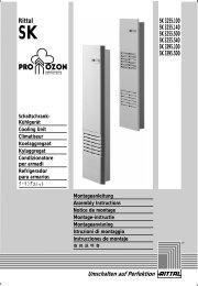
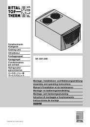
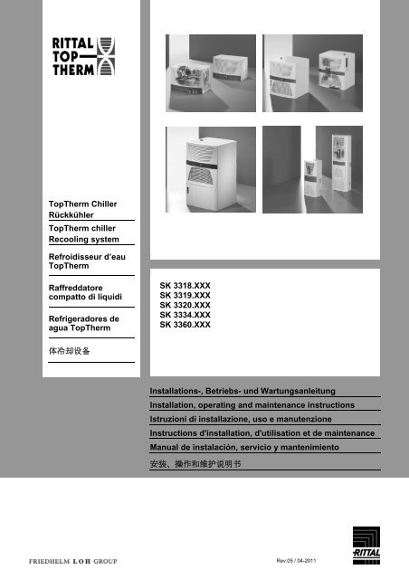
TopTherm Chiller<br />
Rückkühler<br />
TopTherm chiller<br />
Recooling system<br />
Refroidisseur d’eau<br />
TopTherm<br />
Raffreddatore<br />
compatto di liquidi<br />
Refrigeradores de<br />
agua TopTherm<br />
体冷却设备<br />
SK 3318.XXX<br />
SK 3319.XXX<br />
SK 3320.XXX<br />
SK 3334.XXX<br />
SK 3360.XXX<br />
Installations-, Betriebs- und Wartungsanleitung<br />
Installation, operating and maintenance instructions<br />
Istruzioni di installazione, uso e manutenzione<br />
<strong>Instructions</strong> d'installation, d'utilisation et de maintenance<br />
Manual de instalación, servicio y mantenimiento<br />
安装、操作和维护说明书<br />
Rev.05 / 04-2011
Contents<br />
1 Notes on documentation .................. 3<br />
1.1 Other applicable documents .................. 3<br />
1.2 CE conformity ......................................... 3<br />
1.3 Storing the documents ........................... 3<br />
1.4 Symbols used ......................................... 3<br />
2 Safety instructions ............................ 3<br />
2.1 Risks in case of failure to observe the<br />
safety instructions .................................. 3<br />
2.2 Safety instructions for the operator ........ 3<br />
2.3 Safety instructions for assembly,<br />
inspection and maintenance work .......... 3<br />
2.4 Unauthorised operation .......................... 4<br />
2.5 Health risks due to the refrigerant R134a<br />
and the antifreeze .................................. 4<br />
2.5.1 First aid measures .................................. 4<br />
2.5.2 Fire-fighting measures ........................... 4<br />
2.5.3 Protective measures during repairs ....... 4<br />
3 Device description ............................. 5<br />
3.1 General functional description ................ 7<br />
3.1.1 Controller ................................................ 7<br />
3.1.2 Safety devices ........................................ 8<br />
3.1.3 Filter mats .............................................. 8<br />
3.2 Proper use .............................................. 8<br />
3.3 Supply includes ...................................... 8<br />
4 Transportation ................................... 9<br />
5 Assembly and connection .............. 10<br />
5.1 Dimensions .......................................... 10<br />
5.1.1 Dimensions for 3318.6xx and 3319.6xx 10<br />
5.1.2 Dimensions for 3320.6xx and 3334.6xx 10<br />
5.1.3 Dimensions for 3334.66x ..................... 11<br />
5.1.4 Dimensions for 3360.10x ..................... 12<br />
5.1.5 Dimensions for 3360.25x ..................... 13<br />
5.1.6 Dimensions for 3360.47x ..................... 14<br />
5.2 Installation site requirements ............... 15<br />
5.3 Installing the recooling unit ................... 16<br />
5.4 Making the hydraulic connection .......... 16<br />
5.5 Making electrical connection ................ 17<br />
5.5.1 Connecting the power supply ............... 17<br />
5.5.2 Connecting the alarm relay interrogation<br />
device ................................................... 17<br />
5.5.3 External activation (option) ................... 17<br />
5.5.4 Connecting the recooling unit<br />
to the PLC ............................................ 17<br />
5.5.5 Connecting an external room<br />
temperature sensor (optional) .............. 19<br />
5.5.6 Installing the filter mats (optional) ........ 19<br />
6 Commissioning ................................ 20<br />
6.1 Antifreeze ............................................. 20<br />
Contents<br />
6.2 Filling the recooling system with<br />
cooling medium ..................................... 20<br />
6.3 Bleeding the cooling medium pump ...... 21<br />
7 Operation ......................................... 22<br />
7.1 Controls ................................................ 22<br />
7.2 Key functions ........................................ 22<br />
7.2.1 Key functions during operation ............. 22<br />
7.2.2 Key functions during parameter<br />
adjustment ............................................ 23<br />
7.3 Fixed value control or<br />
combined control .................................. 23<br />
7.4 Meaning of the control parameters ....... 24<br />
7.5 Meaning of the error codes ................... 26<br />
7.6 Alarm relay contacts ............................. 28<br />
7.7 PLC outputs .......................................... 28<br />
7.8 Setting the digital real-time clock .......... 28<br />
8 Inspection and maintenance .......... 29<br />
8.1 Maintaining the refrigerant circuit .......... 29<br />
8.2 Water quality ......................................... 30<br />
8.3 Cleaning the condenser ........................ 32<br />
8.4 Cleaning the filter mat (optional) ........... 32<br />
8.5 Draining the cooling medium tank ........ 32<br />
9 Troubleshooting .............................. 33<br />
10 Shutting down and disposal .......... 34<br />
10.1 Shutting down for an extended period .. 34<br />
10.2 Shutting down and disposal .................. 34<br />
11 Technical specifications ................. 35<br />
12 Manufacturer’s guarantee and<br />
customer service ............................. 39<br />
13 Appendix .......................................... 40<br />
13.1 P+ID diagram 3318.600 and 3319.600 . 40<br />
13.2 P+ID diagram 3318.610 and 3319.610 . 41<br />
13.3 P+ID diagram 3320.600, 3334.600,<br />
3334.660, 3360.100, 3360.250,<br />
3360.470 ............................................... 42<br />
13.4 Electrical circuit diagram for 3318.6xx<br />
and 3319.6xx ........................................ 45<br />
13.5 Electrical circuit diagram for 3320.600,<br />
3334.600, 3360.100, 3360.250,<br />
3360.470 ............................................... 46<br />
13.6 Electrical circuit diagram for 3334.660 .. 47<br />
13.7 Spare parts lists .................................... 48<br />
13.8 Accessories .......................................... 58<br />
13.9 EC declaration of conformity ................. 59<br />
Page 2 of 61
1 Notes on documentation<br />
These instructions are aimed at installers and operators<br />
who are familiar with the installation and the<br />
operation of the recooling unit.<br />
It is imperative that you observe the following<br />
You must read and observe these operating instructions<br />
prior to commissioning.<br />
The manufacturer will not accept any liability for<br />
damage or operating problems resulting from failure<br />
to observe these operating instructions.<br />
1.1 Other applicable documents<br />
In conjunction with these instructions the flow diagram<br />
and electrical wiring diagram for the related<br />
model apply, see chapter 13.<br />
1.2 CE conformity<br />
The declaration of conformity is included in the appendix<br />
of these installation and operating instructions.<br />
1.3 Storing the documents<br />
These instructions and all associated documents<br />
constitute an integral part of the product. They must<br />
be supplied to the operator. The plant operator is<br />
responsible for storage of the documents so they<br />
are readily available when needed.<br />
1.4 Symbols used<br />
Please observe the following safety instructions and<br />
other notes in this guide:<br />
Safety and other instructions:<br />
Danger!<br />
Immediate danger to life and limb!<br />
Risk of burns!<br />
Risk of injury due to contact with hot<br />
fluids!<br />
Risk of cuts!<br />
Risk of injury on touching the fins on the<br />
condenser!<br />
Danger!<br />
Danger of death due to electric shock!<br />
Caution!<br />
Possible hazard for the recooling unit.<br />
Caution!<br />
Possible hazard due to discharge of<br />
refrigerant.<br />
Note!<br />
Useful information and special features.<br />
1 Notes on documentation<br />
Symbol for an instructed action:<br />
The bullet point indicates that you should perform an<br />
action.<br />
2 Safety instructions<br />
Please observe the following general safety instructions<br />
when operating and installing the recooling<br />
unit:<br />
Assembly, installation and maintenance must only<br />
be carried out by qualified personnel.<br />
Only use original spare parts and accessories<br />
authorised by the manufacturer to ensure the protection<br />
and safety of the recooling unit. The usage of<br />
other parts will render any liability void.<br />
Do not make any changes to the recooling unit that<br />
have not been agreed with and approved by the<br />
manufacturer.<br />
It is also imperative that you observe the special<br />
safety instructions for the individual activities in the<br />
individual chapters.<br />
2.1 Risks in case of failure to observe<br />
the safety instructions<br />
In case of failure to observe the safety instructions,<br />
people, the environment and the unit may be placed<br />
at risk. Failure to comply with the safety notes<br />
makes all claims for compensation void.<br />
2.2 Safety instructions for the operator<br />
Any existing contact hazard protection for moving<br />
parts must not be removed from units while operational.<br />
Hazards due to electrical power, do not remove<br />
any switch box cover!<br />
2.3 Safety instructions for assembly,<br />
inspection and maintenance work<br />
Cleaning and maintenance work on the unit must<br />
only be performed with the unit shut down. For this<br />
purpose, it is vital to ensure that the unit is disconnected<br />
from the power supply and is secured<br />
against switching back on. It is imperative that you<br />
observe the procedure for shutting down the recooling<br />
unit described in the operating instructions.<br />
All safety devices and protective equipment must be<br />
reattached or put in a functional condition immediately<br />
after the work is complete.<br />
Modifications or changes to the recooling unit are<br />
not allowed.<br />
Only appropriately qualified personnel as defined by<br />
BGR500 chap. 2.35 / EN 378 are allowed to work on<br />
the refrigerant circuit.<br />
Caution!<br />
Possible hazard for the recooling unit.<br />
Page 3 of 61<br />
EN
Do not install the unit without protection outside of<br />
covered areas, or in an explosive or aggressive<br />
environment.<br />
Do not install the unit on an unstable surface or a<br />
surface that is not designed for the weight of the<br />
recooling unit.<br />
Do not bypass any electrical safety devices to make<br />
it possible to operate the recooling unit.<br />
2.4 Unauthorised operation<br />
The safety of the recooling unit supplied is only ensured<br />
if it is used properly, see chapter 3.2. Under<br />
no circumstances should the limit values specified in<br />
the technical specifications be exceeded.<br />
The unit must not be used for the direct cooling of<br />
liquids that are used for foodstuffs (e.g. drinking<br />
water).<br />
Explosion hazard!<br />
The use of the recooling system for cooling<br />
inflammable or pyrophoric substances<br />
is prohibited.<br />
2.5 Health risks due to the refrigerant<br />
R134a and the antifreeze<br />
The refrigerant is a liquefied gas under pressure.<br />
The enclosed R134a safety data sheet must be<br />
observed.<br />
The antifreeze is a liquid fluid. The enclosed Antifrogen<br />
N safety data sheet is to be observed.<br />
2.5.1 First aid measures<br />
(see safety data sheets R134a and Antifrogen N)<br />
2.5.2 Fire-fighting measures<br />
Suitable extinguishing agent<br />
All known extinguishing agents can be used.<br />
2.5.3 Protective measures during repairs<br />
Protective measures<br />
Ensure adequate ventilation.<br />
Personal protection equipment<br />
Hand protection: Protective gloves<br />
Eye protection: Safety glasses<br />
Body protection: Wear safety shoes when handling<br />
pressurised gas bottles.<br />
2 Safety instructions<br />
Page 4 of 61<br />
EN
3 Device description<br />
Recooling units are used for the central and economical<br />
cooling and supply of a cooling medium<br />
(water + glycol, see chapter Water Quality) in the<br />
event of physical separation between the place<br />
where cooling is required and the refrigeration. The<br />
cooling medium is supplied using a pipe system.<br />
Fig. 1 3318.6xx and 3319.6xx View from front<br />
8<br />
7<br />
6<br />
Fig. 2 3318.6xx and 3319.6xx View from rear<br />
Key to figures 1 and 2<br />
1 Rating plate<br />
2 Display<br />
3 Louvred grille for air inlet<br />
4 Louvred grille for air outlet<br />
5 Cable entry<br />
6 Cooling medium inlet<br />
7 Tank drain nozzle for maintenance, transportation and<br />
disposal of the cooling medium<br />
8 Cooling medium return<br />
5<br />
4<br />
3 Device description<br />
Fig. 3 3320.6xx and 3334.6xx View from front<br />
Fig. 4 3320.6xx and 3334.6xx View from rear<br />
Page 5 of 61<br />
EN
1<br />
2<br />
3<br />
Fig. 5 SK 3334.66x View from front<br />
Fig. 6 SK 3334.66x View from rear<br />
4<br />
5<br />
3 Device description<br />
Fig. 7 SK 3360.10x View from front<br />
Fig. 8 SK 3360.25x View from front<br />
2<br />
2<br />
2<br />
9<br />
9 10<br />
Fig. 9 SK 3360.47x View from front<br />
4<br />
9<br />
4<br />
3<br />
10<br />
3<br />
7<br />
5<br />
4<br />
10<br />
3<br />
7<br />
Page 6 of 61<br />
EN
Key to figures 3 to 9<br />
1 Louvred grille for air outlet (two-part)<br />
2 Display<br />
3 Liquid level display of cooling medium<br />
4 Tank filling nozzle for cooling medium<br />
5 Rating plate<br />
6 Louvred grille for air inlet (two-part)<br />
7 Tank drain nozzle for maintenance, transportation and<br />
disposal of the cooling medium<br />
8 Cable entry<br />
9 Cooling medium inlet/outlet<br />
10 Cooling medium return/inlet<br />
The units are equipped with an open reservoir for<br />
the cooling medium. Only recooling unit models<br />
3318.600 and 3319.600 have a closed cooling medium<br />
circuit, 2.5 bar.<br />
For the closed recooling units, we recommend the<br />
installation of a pressure manometer, 0 – 6 bar, in<br />
the cooling medium circuit.<br />
3.1 General functional description<br />
14<br />
13<br />
12<br />
11<br />
P<br />
S<br />
10<br />
1 2<br />
Fig. 10 Refrigerant circuit (schematic diagram: example,<br />
units with open refrigerant circuit)<br />
Key<br />
1 Condenser, air-cooled<br />
2 Condenser fan<br />
3 Filter dryer<br />
4 Expansion valve<br />
5 Water level switch (optional)<br />
6 Temperature probe<br />
7 Fill nozzle<br />
8 Tank drain<br />
9 Cooling medium pump<br />
10 Cooling medium tank<br />
11 Flow switch<br />
12 Evaporator (plate heat exchanger)<br />
13 Compressor<br />
14 Pressure switch<br />
3<br />
4<br />
9<br />
5<br />
6<br />
7<br />
8<br />
3 Device description<br />
The recooling system comprises the four main components:<br />
evaporator (12), compressor (13), condenser<br />
(1) with fan (2) as well as the control or expansion<br />
valve (4), which are connected together by<br />
pipes. A pressure switch (14) limits the maximum<br />
pressure in the refrigerant circuit. The R134a<br />
(CH2FCF3) refrigerant is free from chlorine. Its<br />
Ozone Depletion Potential (ODP) is 0.<br />
A filter dryer (3) which is integrated into the hermetically<br />
sealed refrigerant circuit provides effective<br />
protection against moisture, acid, dirt particles, and<br />
foreign bodies. A temperature control with temperature<br />
probe (6) ensures that the cooling medium is<br />
maintained at a preset setpoint temperature.<br />
In the evaporator (12), the liquid refrigerant is converted<br />
to a gaseous state. The heat necessary for<br />
this purpose is taken from the cooling medium in the<br />
plate heat exchanger, which has the effect of cooling<br />
the cooling medium. The refrigerant is heavily<br />
compressed in the compressor (13). As a result the<br />
refrigerant has a higher temperature than the ambient<br />
air. This heat is dissipated to the ambient air<br />
over the surface of the condenser (1), resulting in<br />
the refrigerant liquefying again.<br />
The refrigerant is injected into the evaporator (12)<br />
using a thermostatic expansion valve (4), as a result<br />
it is expanded and is therefore able to absorb the<br />
heat from the cooling medium (water, water-glycol<br />
mixture).<br />
The cooling medium is pumped to the equipment in<br />
a closed circuit using a pump (9) and cooling medium<br />
tank (10). The flow switch (11) ensures the<br />
evaporator (12) is protected against freezing if the<br />
flow rate is too low. The level switch (5, optional)<br />
protects the pump (9) against dry running. The cooling<br />
medium (water or water-glycol mixture) feed<br />
temperature is regulated using the temperature<br />
probe (6) in the tank.<br />
You will find the flow diagrams for the individual<br />
types of units in chapter 13.<br />
3.1.1 Controller<br />
The recooling units are fitted with a controller for<br />
setting the functions of the recooling unit. Operating<br />
states are displayed using a display unit and parameters<br />
can be set using buttons.<br />
Page 7 of 61<br />
EN
3.1.2 Safety devices<br />
The recooling unit has a pressure switch in accordance<br />
with EN 12263, tested at component level, in<br />
the refrigerant circuit; this device is set to the maximum<br />
permissible pressure (PS). An automatic reset<br />
device ensures that the system continues to work<br />
after the pressure drops (autoreset).<br />
Temperature monitoring prevents the evaporator<br />
coil from icing over. If there is a risk of icing, the<br />
compressor switches itself off and automatically<br />
switches itself back on again at higher temperatures.<br />
The refrigerant compressor motor and the fan motors<br />
are equipped with thermal winding protection<br />
switches against excess current and excess temperatures.<br />
To ensure that the compressor runs reliably and<br />
without problems (for example after reaching the<br />
setpoint temperature or after a fault), the compressor<br />
automatically switches back on after a delay of<br />
180 seconds.<br />
The recooling unit has two integrated floating fault<br />
signal contacts (see circuit diagram of the relevant<br />
unit type, sections 13.4 and 13.5). Individual fault<br />
messages can be interrogated via an integrated<br />
Sub-D socket using an external PLC controller.<br />
3.1.3 Filter mats<br />
If there is coarse dust and fluff in the ambient air, we<br />
recommend fitting an additional filter mat (available<br />
as an accessory) in the recooling unit (provision has<br />
been made for installation). You will need to replace<br />
the filter regularly depending on the amount of dust.<br />
For air that contains an oil mist, we recommend<br />
metal filter mats (accessory). These may be cleaned<br />
with suitable detergents and reused.<br />
Automatic filter mat monitoring is built into recooling<br />
units (turned off by default). The device measures<br />
the dirt in the filter mat by comparing the ambient<br />
temperature and the air output temperature on the<br />
condenser. As the filter mat becomes increasingly<br />
dirty, the pressure in the refrigerant circuit rises and<br />
with it the temperature of the output air. This results<br />
eventually in a fault message.<br />
3 Device description<br />
3.2 Proper use<br />
<strong>Rittal</strong> recooling units have been developed and designed<br />
in accordance with the state of the art and<br />
the recognised rules governing safety. Nevertheless,<br />
if used improperly, they may pose a threat to<br />
life and limb or cause damage to property.<br />
The TopTherm recooling units described in these<br />
instructions must only be used for cooling water or a<br />
water-glycol mixture.<br />
If using other fluids (e.g. de-ionised water), please<br />
refer to the technical specifications contained in the<br />
appendix, or contact the manufacturer. Under no<br />
circumstances should the limit values specified in<br />
the technical specifications be exceeded.<br />
Explosion hazard!<br />
The use of the recooling unit for cooling<br />
inflammable or explosive substances is<br />
prohibited.<br />
3.3 Supply includes<br />
The unit is supplied in packaging in a fully assembled<br />
state.<br />
Please check the scope of supply for completeness.<br />
Check the packaging carefully for signs of damage.<br />
Traces of oil on damaged packaging indicate a loss<br />
of refrigerant. The unit may have leaked. Any packaging<br />
damage may be the cause of a subsequent<br />
functional failure.<br />
Qty. Description<br />
1 Recooling unit<br />
1 Dispatch bag with:<br />
1 – Operating and installation instructions<br />
1 – Eyebolt for transportation<br />
Tab. 1 Supply includes<br />
Page 8 of 61<br />
EN
4 Transportation<br />
For water cooling medium:<br />
If the recooling system is stored or transported at<br />
temperatures below freezing, you must completely<br />
drain the cooling medium circuit and flush it with a<br />
water-glycol mixture to prevent frost damage. This<br />
instruction also applies to the external condenser<br />
circuit for a water-cooled condenser (option).<br />
Only transport the recooling unit in its original packaging<br />
material before commissioning for the first<br />
time. In case of damage, inform the manufacturer<br />
without delay.<br />
When transporting the recooling unit, the weight<br />
specified on the rating plate must be taken into consideration.<br />
Use lifting gear with an appropriate minimum load<br />
capacity.<br />
To prevent transport damage to the unit, proceed as<br />
follows:<br />
Only transport the unit in an upright position.<br />
Fig. 11 Eyebolt for transportation (331x.6xx shown here as<br />
an example)<br />
Only transport the unit on the pallet supplied with<br />
the unit or with the eyebolt provided (1).<br />
Prevent excessive vibration.<br />
If it is necessary to move the unit in the factory, you<br />
must disconnect all connections on the unit.<br />
Before transporting, empty the water circuit and tank<br />
(if applicable), see chapter 8.<br />
1<br />
4 Transportation<br />
Page 9 of 61<br />
EN
5 Assembly and connection<br />
5.1 Dimensions<br />
5.1.1 Dimensions for 3318.6xx and 3319.6xx<br />
600 430<br />
20<br />
C<br />
400<br />
Fig. 12 Dimensions for 3318.6xx and 3319.6xx<br />
5.1.2 Dimensions for 3320.6xx and 3334.6xx<br />
645<br />
605<br />
Fig. 13 Dimensions for 3320.6xx and 3334.6xx<br />
5 Assembly and connection<br />
Page 10 of 61<br />
EN
5.1.3 Dimensions for 3334.66x<br />
Fig. 14 Dimensions for 3334.66x<br />
5 Assembly and connection<br />
Page 11 of 61<br />
EN
5.1.4 Dimensions for 3360.10x<br />
Mounting cut-out for external mounting/partial internal mounting<br />
5 Assembly and connection<br />
External mounting Partial internal mounting<br />
Before drilling, check the dimensions of the drilling template.<br />
Stick the drilling template onto the side panel or door of the enclosure using adhesive tape.<br />
Mark, drill and deburr the holes.<br />
Attach the recooling unit using the assembly parts supplied.<br />
Page 12 of 61<br />
EN
5.1.5 Dimensions for 3360.25x<br />
Mounting cut-out for external mounting/partial internal mounting<br />
5 Assembly and connection<br />
External mounting Partial internal mounting<br />
Before drilling, check the dimensions of the drilling template.<br />
Stick the drilling template onto the side panel or door of the enclosure using adhesive tape.<br />
Mark, drill and deburr the holes.<br />
Attach the recooling unit using the assembly parts supplied.<br />
Page 13 of 61<br />
EN
5.1.6 Dimensions for 3360.47x<br />
Mounting cut-out for external mounting/partial internal mounting<br />
External mounting<br />
5 Assembly and connection<br />
Partial internal mounting<br />
Before drilling, check the dimensions of the drilling template.<br />
Stick the drilling template onto the side panel or door of the enclosure using adhesive tape.<br />
Mark, drill and deburr the holes.<br />
Attach the recooling unit using the assembly parts supplied.<br />
Page 14 of 61<br />
EN
5.2 Installation site requirements<br />
The site must be free from excessive dirt and moisture.<br />
The ambient temperature must not exceed 43°C.<br />
Install the recooling unit close to the equipment<br />
being cooled to avoid long distances and related<br />
performance losses.<br />
Performance losses arise in particular due to:<br />
Pressure drops in the refrigerant piping system<br />
caused by resistance in the pipes and individual<br />
components such as shut-off valves and pipe<br />
bends.<br />
Heat transfer in uninsulated pipes.<br />
Select the installation site such that:<br />
Easy access is possible at any time. This situation<br />
will ease maintenance and repair.<br />
The condenser fan does not operate in a "shortcircuit",<br />
whereby the warm exhaust air from the condenser<br />
is drawn in again by the condenser's fan.<br />
An "air short-circuit" will result in a loss of performance<br />
of the recooling unit.<br />
Maintain the following minimum distances (in mm)<br />
from the wall:<br />
Fig. 15 Space requirements<br />
5 Assembly and connection<br />
TopTherm recooling unit for wall mounting<br />
AIR OUT<br />
AIR IN<br />
300<br />
300<br />
Note!<br />
For unit types 3318.6xx and 3319.6xx,<br />
the airflow passes through the unit from<br />
front to back.<br />
With unit types 3320.6xx and 3334.6xx<br />
the airflow passes through the unit from<br />
back to front.<br />
Ensure the room is adequately ventilated by installing<br />
the recooling unit such that the heat dissipated<br />
by the unit does not heat the room excessively.<br />
The ambient temperature will increase due to the<br />
heat dissipated. This temperature increase may<br />
cause a loss of performance of the recooling unit.<br />
In case of installation in a "small" room, it is imperative<br />
that you provide forced ventilation, as otherwise<br />
the heat dissipated will build up.<br />
The connection of ducts for fresh and exhaust air to<br />
our devices is not suitable, as these units are<br />
equipped with axial fans and these cannot build up<br />
the necessary additional air pressure.<br />
To prevent performance losses, do not install the<br />
recooling unit near any form of heating.<br />
Outdoor siting<br />
Cooling units must be installed such that they cannot<br />
become damaged by internal traffic and transport<br />
operations.<br />
Page 15 of 61<br />
EN
5.3 Installing the recooling unit<br />
Install the recooling unit on an even, firm surface.<br />
The maximum permissible deviation from the vertical<br />
is 2°.<br />
Avoid the production of noise due to vibration (vibration<br />
dampers, sheets of foam rubber).<br />
5.4 Making the hydraulic connection<br />
Caution!<br />
Risk of damage to the circulation pump<br />
due to soiling in the cooling medium<br />
circuit! Flush the cooling medium circuit<br />
prior to connecting to the recooling unit.<br />
The cooling medium outlet on the recooling unit (see<br />
(6) Fig. 2 or (9) Fig. 4) must be connected to the<br />
cooling medium inlet on the equipment to be cooled.<br />
The cooling medium inlet on the recooling unit (see<br />
(8) Fig. 2 or (10) Fig. 4) must be connected to the<br />
cooling medium outlet on the equipment to be<br />
cooled.<br />
Use only insulated pipes and/or hoses to connect<br />
the equipment to the recooling unit.<br />
The nominal size of the piping must be at least the<br />
same as the nominal size of the medium connections<br />
on the unit, and on pressure-sealed units must<br />
be approved for the maximum pressure expected,<br />
see chapter 11.<br />
Note!<br />
The use of steel pipes or galvanised steel<br />
pipes is inadmissible.<br />
For pressure-sealed units (3318.6xx and 3319.6xx)<br />
Install a pressure manometer, 0 to 6 bar, in the cooling<br />
medium circuit.<br />
For types 3320.6xx, 3334.6xx and 3360.47x only:<br />
Prior to commissioning, it is imperative that the cooling<br />
medium pump is filled with cooling medium and<br />
bled, see chapter 6.<br />
In the case of a water-cooled condenser (optional),<br />
the operator must:<br />
Make the cooling water connections.<br />
Caution!<br />
Risk of damage for the unit!<br />
Insufficient pressure (on pressure-sealed<br />
units) and an excessively low flow rate<br />
will trigger the safety devices in the unit.<br />
Pay attention to the required minimum<br />
pressure and the minimum flow rate, see<br />
chapter 11.<br />
5 Assembly and connection<br />
Only for types 3318.61x, 3319.61x, 3320.6xx,<br />
3334.6xx, 3334.66x, 3360.xxx that are open to the<br />
atmosphere:<br />
If the cooler on the equipment to be cooled is higher<br />
than the recooling unit, we recommend installing a<br />
non-return valve in the feed as well as a solenoid<br />
valve in the cooling medium circuit return to prevent<br />
the tank from overflowing.<br />
Caution!<br />
Risk of damage for the cooling medium<br />
pump due to dry running! If it is possible<br />
to shut off the circuit to the equipment to<br />
be cooled, you must install a bypass<br />
valve (can be ordered as an option) between<br />
the feed and return to protect the<br />
cooling medium pump.<br />
Page 16 of 61<br />
EN
5.5 Making electrical connection<br />
It is imperative that you follow the instructions<br />
given below:<br />
When carrying out the electrical installation, observe<br />
all applicable national and regional regulations as<br />
well as the regulations from the responsible utility<br />
company. Electrical installation must only be carried<br />
out by a qualified electrician who is responsible for<br />
compliance with the existing standards and regulations.<br />
The voltage and frequency of the connection must<br />
correspond to the values stated on the rating plate.<br />
The recooling unit must be connected to the mains<br />
via an all-pole isolating device.<br />
No additional temperature control is allowed to be<br />
connected upstream of the recooling system on the<br />
supply side.<br />
Install the pre-fuse cited on the rating plate (miniature<br />
circuit-breaker "K" characteristic or slow fuse) to<br />
protect the cable and equipment from short-circuits.<br />
The mains connection must ensure low-noise potential<br />
equalisation. Recooling units must always be integrated<br />
into the building's equipotential bonding<br />
system.<br />
The conductor cross-sections of the power cable<br />
must be selected according to the rated current (see<br />
rating plate).<br />
The recooling unit does not have its own overvoltage<br />
protection. Measures must be taken by the operator<br />
at the supply end to ensure effective lightning<br />
and overvoltage protection. The mains voltage must<br />
not exceed the tolerance of +6/-10 %, see chapter<br />
11.<br />
On three-phase units: The connection must be<br />
made with the field rotating clockwise. The direction<br />
of rotation of the field can be measured at the connection<br />
terminals L1, L2 and L3. Connection with a<br />
clockwise rotating field ensures that all three-phase<br />
motors rotate in the correct direction.<br />
In case of an integrated transformer (optional): Ensure<br />
correct voltage connection on the primary side.<br />
If you want to evaluate the fault codes for fault signals<br />
from the recooling unit using the alarm relay,<br />
you must also connect an appropriate low-voltage<br />
cable to terminals 3 – 8, see circuit diagram for the<br />
relevant unit type in chapter 13.<br />
If the recooling system requires remote switching,<br />
terminals 1 and 2 can be used for this purpose (see<br />
the circuit diagram for the relevant unit type in chapter<br />
13) together with the appropriate programming<br />
(parameter 18), see chapter 7.4.<br />
5 Assembly and connection<br />
5.5.1 Connecting the power supply<br />
The units are prewired ready for connection in the<br />
factory and equipped with a twelve-wire connection<br />
cable (length 2.5 m).<br />
Make the electrical connection as per the electrical<br />
circuit diagram (see circuit diagram for the relevant<br />
unit type in chapter 13).<br />
5.5.2 Connecting the alarm relay interrogation<br />
device<br />
You can also query fault messages with two floating<br />
contacts on a separate connection clamp of the<br />
recooling unit. The necessary wires are already<br />
present in the connection cable and are connected<br />
in the device.<br />
Connect the correspondingly labelled wires of the<br />
connection cable to the controller as shown in the<br />
electrical circuit diagram (see circuit diagram for the<br />
relevant unit type in chapter 13).<br />
For details on the assignment of alarm relay contacts<br />
when an error code is displayed, see section<br />
7.6.<br />
5.5.3 External activation (option)<br />
The unit has been prepared with the option for control<br />
via an external signal. To implement this, the<br />
customer must connect 24 V DC to contacts 1 and 2<br />
(note polarity; see circuit diagram according to unit<br />
type) and set parameter 18 to 1 (see description of<br />
the controller).<br />
5.5.4 Connecting the recooling unit to the<br />
PLC<br />
To evaluate individual fault messages, the unit can<br />
be connected to a programmable logic controller<br />
(PLC). The connection is made with a 15-pole Sub-<br />
D socket.<br />
Use a suitable line to connect the PLC to the 15pole<br />
Sub-D socket (see (4) Fig. 17 and (5) Fig. 13).<br />
For types 3318.6xx and 3319.6xx:<br />
3<br />
Fig. 16 Preparing the PLC connection for types 3318.6xx<br />
and 3319.6xx<br />
2<br />
1<br />
Page 17 of 61<br />
EN
Remove the louvred grille (3) on the rear of the recooling<br />
unit.<br />
Remove the belt (2) and the housing (1).<br />
3<br />
4<br />
Fig. 17 PLC connection for types 3318.6xx and 3319.6xx<br />
Guide a suitable connection cable into the unit via<br />
the additional cable gland provided (see (5) Fig. 2).<br />
Connect the cable to the 15-pole Sub-D socket, see<br />
(4) Fig. 17 or (5) Fig. 13.<br />
For types 3320.6xx and 3334.6xx:<br />
Fig. 18 Preparing the PLC connection<br />
for types 3320.6xx and 3334.6xx<br />
Remove the louvred grille (3+4) on the rear of the<br />
recooling unit.<br />
Remove the filter mat, if applicable (2).<br />
2<br />
1<br />
5 Assembly and connection<br />
Fig. 19 PLC connection for types 3320.6xx and 3334.6xx<br />
5<br />
4<br />
Fig. 20 PLC connection for type 3334.66x<br />
Guide a suitable connection cable into the unit via<br />
the additional cable gland provided (see (8) Fig. 4).<br />
Connect the cable to the 15-pole Sub-D socket, see<br />
(5) Fig. 13.<br />
Page 18 of 61<br />
EN
SPS 1<br />
SPS 8<br />
24V DC ext.<br />
1<br />
2<br />
3<br />
4<br />
5<br />
6<br />
7<br />
8<br />
Fig. 21 Assignment of PLC contacts<br />
9<br />
10<br />
11<br />
12<br />
13<br />
14<br />
15<br />
CTS<br />
RTS<br />
RXD<br />
TXD<br />
NC<br />
GND<br />
For details on the assignment of PLC contacts when<br />
an error code is displayed, see section 7.7.<br />
5.5.5 Connecting an external room temperature<br />
sensor (optional)<br />
The units allow for combined room-temperaturebased<br />
control and are equipped for this purpose<br />
with a B5 connection for an external room temperature<br />
sensor available as an optional accessory (cable<br />
length 4 m).<br />
Fig. 22 Cable routing to room temperature sensor<br />
Guide a suitable connection cable into the unit via<br />
the additional cable gland provided (see (A)<br />
Fig. 22).<br />
Connect the connection cable on the electrical<br />
switch box to socket contact B5, see (3) Fig. 17 or<br />
(4) Fig. 19.<br />
After completing the connection work:<br />
Re-install the unit parts in the reverse order according<br />
to the device type.<br />
5.5.6 Installing the filter mats (optional)<br />
If there is coarse dust and fluff in the ambient air, we<br />
recommend installing an additional fleece filter mat<br />
(available as an accessory) in the recooling unit.<br />
5 Assembly and connection<br />
Metal filter mats (accessory) are available for air<br />
containing oil condensation.<br />
For types 3318.6xx and 3319.6xx only:<br />
Fig. 23 3318.6xx and 3319.6xx Install filter mat<br />
Pull the louvred grille (1) on the front of the recooling<br />
unit (air inlet) away from the housing.<br />
Insert the filter mat (2) (Model No. 3286.510) into<br />
the louvred grille as shown in Fig. 23 and push it<br />
back onto the housing.<br />
For types 3320.6xx and 3334.6xx only:<br />
Fig. 24 3320.6xx and 3334.6xx Install filter mat<br />
Remove the upper and lower louvred grille (1) on<br />
the rear of the recooling unit by carefully pulling it off<br />
the housing.<br />
Remove the belt. To do so, unscrew the screws.<br />
Insert the filter mat (2) (Model No. 3286.520) into<br />
the unit from above, as shown in Fig. 24.<br />
Reinstall the belt onto the unit.<br />
Press both louvred grilles back onto the housing.<br />
1<br />
2<br />
Page 19 of 61<br />
EN
6 Commissioning<br />
The recooling unit does not have its own main<br />
switch to switch the recooling unit on and off. It must<br />
be switched on and off by the higher-level controller.<br />
6.1 Antifreeze<br />
As standard, the units are not suitable for operation<br />
below the specified minimum temperature (see<br />
chapter 11). The units are always to be used with a<br />
water-glycol mixture for the coolant with a maximum<br />
glycol content of between 20 and 30% by volume.<br />
The recommended antifreeze is Antifrogen N or our<br />
<strong>Rittal</strong> Rifrost.<br />
Other types of antifreeze are possible in specific<br />
cases, however only in consultation with the manufacturer.<br />
Note!<br />
Only use distilled or de-ionised water in<br />
recooling units specified for such use (see<br />
chapter 11).<br />
Caution!<br />
Risk of damage for pipes and seals!<br />
Other additives may damage the pipes<br />
and the seal on the cooling medium<br />
pump and are therefore not allowed.<br />
To prevent problems in the cooling medium circuit<br />
(also water-cooled units), it is imperative that the<br />
VEB Cooling Medium Guidelines (VGB-R 455 P) are<br />
observed.<br />
You can read and determine the correct glycol content<br />
with the aid of a refractometer, available from<br />
the following supplier: Georg Pforr -gefo- GmbH &<br />
Co. KG, Holterkamp 16, D-40880 Ratingen, Germany.<br />
http://www.gefo.de.<br />
6.2 Filling the recooling system with<br />
cooling medium<br />
The composition of the cooling medium is described<br />
in chapter 8.<br />
For commissioning, proceed as follows:<br />
Ensure that any shut-off valves installed in the cooling<br />
medium circuit are open.<br />
1<br />
6 Commissioning<br />
Fig. 25 3318.610 and 3319.610 Filling with the cooling<br />
medium<br />
For types 3318.610 and 3319.610:<br />
Fill the unit with cooling medium via the fill nozzle<br />
(1) (see Fig. 25) up to the full mark in the tank.<br />
For types 3320.6xx and 3334.6xx:<br />
Fill the unit with cooling medium via the fill nozzle<br />
(4) (see Fig. 4). Check the level on the level gauge<br />
(3) (see Fig. 3).<br />
For types 3318.600 and 3319.600:<br />
For pressure-sealed cooling medium circuits: Fill the<br />
circuit using a filler pump or water hose via the feed,<br />
return or drain cock (Fig. 2), and build up a prepressure<br />
of 1.2 – 2 bar. This pressure can be read<br />
from the pressure manometer you have fitted.<br />
For types 3318.6xx, 3319.6xx, 3320.6xx and<br />
3334.6xx:<br />
Switch on the power supply to the recooling unit via<br />
the higher-level controller.<br />
The indicators on the controller illuminate and indicate<br />
the actual feed temperature of the cooling medium.<br />
Check the direction of rotation of the motors (see<br />
direction of rotation arrows on the cooling medium<br />
pump and on the condenser fan).<br />
Note!<br />
If the compressor and condenser fan do<br />
not start to operate, the temperature of the<br />
cooling medium added is lower than the<br />
setpoint temperature set.<br />
If necessary, lower the setpoint temperature momentarily;<br />
see section 7.4.<br />
Page 20 of 61<br />
EN
For types 3318.6xx and 3319.6xx:<br />
The cooling air is drawn in from the front and expelled<br />
to the rear.<br />
For types 3320.6xx and 3334.6xx:<br />
The cooling air is drawn in from the rear and expelled<br />
to the front.<br />
If required, the condenser fan is activated by the<br />
temperature controller.<br />
If the direction of rotation is incorrect, you must<br />
change over the connections for phases L1 and L2<br />
on the recooling unit's terminal strip for the power<br />
supply, see (1) Fig. 17 or (2) Fig. 19.<br />
6.3 Bleeding the cooling medium pump<br />
Bleed the pipes and top-up the cooling medium.<br />
For types 3318.6xx, 3319.6xx, 3360.1xx, 3360.25x<br />
only:<br />
The cooling medium pump fills by itself and does not<br />
need to be bled.<br />
For types 3320.6xx and 3334.6xx only:<br />
Fig. 26 Bleeding the cooling medium pump<br />
(types 3320.6xx and 3334.6xx only)<br />
For type 3334.66x only:<br />
6 Commissioning<br />
Fig. 27 Bleeding the cooling medium pump SK 3334.66x<br />
For type 3360.47x only:<br />
1<br />
Fig. 28 Bleeding the cooling medium pump SK 3360.47x<br />
Bleed the cooling medium pump by loosening the<br />
bleed screw a little (see (1) Fig. 26/27/28). As soon<br />
as cooling medium escapes, re-tighten the screw.<br />
In case of a water-cooled condenser (optional):<br />
Activate the external condenser circuit for the condenser<br />
(optional, provided by the operator).<br />
During commissioning:<br />
Check the connecting pipes and pipe connections<br />
for leaks.<br />
Page 21 of 61<br />
EN
7 Operation<br />
The recooling unit is switched on and off by the<br />
higher-level control. It operates automatically, i.e.<br />
the cooling medium is pumped continuously and<br />
heat extracted from it during this process.<br />
A controller provides automatic control based on the<br />
hysteresis set. The controller has a display for the<br />
indication of temperature values and buttons for<br />
setting operating parameters.<br />
7.1 Controls<br />
Fig. 29 Controls – controller<br />
Key<br />
1 7-segment display<br />
2 Temperature unit LEDs<br />
3 Control keys<br />
The units have a 3-digit 7-segment display to indicate<br />
operating states and control keys to set operating<br />
parameters.<br />
After the power supply is switched on, the display<br />
"E0" appears initially for approx. 20 seconds to indicate<br />
that the unit is operational (boot phase controller).<br />
After the boot phase, the chiller will start to<br />
work.<br />
During operation, the inlet temperature (to the<br />
equipment) of the cooling medium circuit is displayed<br />
via the indicators, alternating with any error<br />
messages that are present in the form of error<br />
codes; see section 7.5. Two LEDs °C and °F are<br />
used as indicators for the temperature unit °C (Celsius)<br />
or °F (Fahrenheit).<br />
You can perform the following activities via indicators<br />
and control keys:<br />
Reading temperature values<br />
Reading from error memory<br />
Acknowledging error messages<br />
Resetting the pump<br />
Reading and setting parameters for the controller<br />
The measurement range for temperature measurements<br />
is:<br />
Celsius: –40°C to 70°C<br />
Fahrenheit: –40°F to 158°F<br />
Temperatures are shown with a resolution of 0.1° in<br />
the following ranges:<br />
Celsius: –9.9°C to 70.0°C<br />
Fahrenheit: –9.9°F to 99.9°F<br />
7 Operation<br />
7.2 Key functions<br />
You can use the control keys to change control parameters<br />
within the assigned ranges (min. to max.<br />
value). Tab. 2 in section 7.4 shows the parameters<br />
that may be set. The function of the control keys<br />
(see (3) Fig. 29) changes depending on which control<br />
level you are on.<br />
7.2.1 Key functions during operation<br />
The keys have the following functions during operation:<br />
key:<br />
+<br />
Display of software version: Press and hold<br />
Delete error memory when error memory is activated:<br />
Press and hold 10 seconds<br />
key:<br />
Display of temperature values from sensors 1 to<br />
5, one after the other: Press repeatedly<br />
Sensor 1: Cooling medium temperature (displayed<br />
continuously or after 30 sec. menu timeout)<br />
Sensor 2: Icing of evaporator unit<br />
Sensor 3: Condenser, external (filter mat)<br />
Sensor 4: Condenser, internal (filter mat)<br />
Sensor 5: Room temperature (if combined control<br />
active, see section 7.3)<br />
key:<br />
Manual alarm reset:<br />
Parameter adjustment is interrupted if no key<br />
is pressed for approx. 30 seconds (or 10 seconds<br />
if an alarm is outstanding). If this is not<br />
done, the value will not be saved!<br />
The display shows the preset values again.<br />
keys:<br />
Jump to the parameterisation level, see<br />
section 7.2.2: Press both keys and hold<br />
for about 5 seconds.<br />
To exit the parameterisation level, press<br />
both keys again and hold for about 5 seconds.<br />
Page 22 of 61<br />
EN
7.2.2 Key functions during parameter adjustment<br />
Parameter adjustment is cancelled if you do not<br />
press any key for about 30 minutes. When this happens,<br />
any value in the process of being changed will<br />
not be saved! The indicators will then show normal<br />
operating values again (actual temperature of the<br />
cooling medium or the error code).<br />
key:<br />
in selection mode: Parameter number is incremented<br />
from P01 to P20.<br />
in editing mode: Parameter value is increased.<br />
key:<br />
in selection mode: Parameter number is decremented<br />
from P01 to P20.<br />
in editing mode: Parameter value is decreased.<br />
key:<br />
in parameter selection: switch to editing mode.<br />
in editing mode: Accept parameter and increment<br />
to the next parameter.<br />
After the last parameter (display 'End'): Exit parameter<br />
adjustment.<br />
Example: Change unit in the temperature display<br />
You can have temperature values displayed in degrees<br />
Celsius or Fahrenheit. To change the display<br />
unit, proceed as follows:<br />
+ Press both keys and hold for about<br />
, You can use these keys to switch be-<br />
, Press both keys and hold for about<br />
5 seconds.<br />
You are on the parameterisation level.<br />
Press key until parameter P17 is displayed.<br />
Press key to switch into editing mode.<br />
tween display in Celsius and Fahrenheit.<br />
Press key to confirm entry and switch to<br />
next parameter.<br />
5 seconds to exit the parameter level.<br />
7 Operation<br />
7.3 Fixed value control or combined<br />
control<br />
Recooling units allow for both fixed value control<br />
and combined room temperature-based control.<br />
The units are set to "Fixed value control" in the factory.<br />
If you have connected an external room temperature<br />
sensor, see section 5.5.5, available as an optional<br />
accessory, you can set control mode "Combined<br />
control" on the controller with parameter 13, see<br />
section 7.4.<br />
In combined control, additional control parameters<br />
must be set or taken into consideration; see section<br />
7.4.<br />
Fixed value control<br />
Tw / °C<br />
20<br />
Combined control<br />
Control with positive hysteresis<br />
C on = Tambient – diff. + Hyst.<br />
C off = Tambient – diff.<br />
Temp./°C<br />
35<br />
30<br />
25<br />
20<br />
15<br />
10<br />
5<br />
Setpoint Tw: 20°C<br />
Hysteresis: 2 K<br />
Difference: -5K<br />
Hysteresis: +2K<br />
Parameter example:<br />
1 3 4 5 6 7 8 9<br />
Cooling ON<br />
Cooling OFF<br />
t/min<br />
Cooling ON<br />
Cooling OFF<br />
t/min<br />
Ambient temperature<br />
Difference to ambient temperature P 3 = -5<br />
combined control P 6 = 2<br />
C on = cooling on T ambient = ambient temperature diff. = difference<br />
C off = cooling off T Hyst. = hysteresis Smax = maximum<br />
Smin = minimum<br />
Page 23 of 61<br />
EN
7.4 Meaning of the control parameters<br />
No. Parameter Min. value Max. value Factory<br />
setting<br />
Fixed value control<br />
1<br />
2<br />
Setpoint temperature<br />
with fixed value control<br />
Switching hysteresis<br />
with fixed value control<br />
Combined control<br />
3<br />
Difference from room temperature<br />
10.0°C 30.0°C 20.0°C<br />
2 K 5 K 2 K<br />
-10.0°C 10.0°C 5.0°C<br />
4 Minimum setpoint 7.0°C P5 10.0°C<br />
5 Maximum setpoint P4 35.0°C 28.0°C<br />
6<br />
7<br />
8<br />
Switching hysteresis,<br />
combined control<br />
Tolerance for error message<br />
"F.01"<br />
Heater control<br />
(Medium)<br />
2 K 5 K 2 K<br />
3.0°C 15.0°C 5.0°C<br />
1.0°C<br />
5.0°C<br />
(+ OFF)<br />
9 Internal real-time clock - - -<br />
10<br />
11<br />
12<br />
Switching times<br />
Compressor<br />
Switching times<br />
Heater<br />
Lock "1"<br />
(password protection)<br />
OFF<br />
OFF ON OFF<br />
OFF ON OFF<br />
1 999 123<br />
13 Control mode Ct Ft Ft<br />
14<br />
Heater function antifreeze<br />
(optional)<br />
OFF ON OFF<br />
Setting Explanation<br />
7 Operation<br />
If fixed value control is set for parameter<br />
13, the setpoint temperature can be<br />
selected here.<br />
If fixed value control is set for parameter<br />
13, the switching hysteresis can be<br />
determined here.<br />
If combined control is set for parameter<br />
13, the setpoint temperature can be set<br />
with this parameter as the difference<br />
compared to room temperature. Negative<br />
values result in a setpoint above<br />
the ambient temperature.<br />
If combined control is set for parameter<br />
13, the lower setpoint can be limited<br />
with this value.<br />
If combined control is set for parameter<br />
13, the upper setpoint can be limited<br />
with this value.<br />
If combined control is set for parameter<br />
13, the switching hysteresis can be<br />
determined here.<br />
If the cooling medium temperature<br />
exceeds the activation temperature of<br />
the compressor by the value set here,<br />
error message F.01 and an alarm are<br />
generated.<br />
Optional: If a tank heater is installed.<br />
The heater will cut in if the tank temperature<br />
drops below the value set<br />
here.<br />
If OFF is set, the heater will never cut<br />
in.<br />
One after another, the hour (0 .. 24),<br />
minute (0 .. 59), year (00 .. 99), month<br />
(1 .. 12), day (1 .. 31), summertime<br />
(OFF, EU; USA, S1 .. S12, E1 .. E12)<br />
are displayed.<br />
Select the day of the week (1Mo .. 7Su,<br />
ESC), start time (hh, mm), end time<br />
(hh, mm)<br />
Only if P8 not OFF.<br />
Select the day of the week (1Mo .. 7Su,<br />
ESC), start time (hh, mm), end time<br />
(hh, mm)<br />
To call up parameters P13 .. P19, key<br />
number 123 must be set.<br />
Ct: Combined control<br />
Ft: Fixed value control<br />
Optional if a heater is installed.<br />
ON: +2°C OFF: +5°C<br />
Page 24 of 61<br />
EN
No. Parameter Min. value Max. value Factory<br />
setting<br />
15 Hot gas bypass (optional) OFF ON OFF<br />
16<br />
Setpoint for filter mat<br />
monitoring<br />
4.0 K<br />
70.0 K<br />
(+ OFF)<br />
17 Changeover °C/°F °C °F °C<br />
18<br />
19<br />
Evaluation of the external<br />
enable signal<br />
Acknowledgement of error<br />
messages<br />
1<br />
5<br />
(+ OFF)<br />
OFF<br />
OFF<br />
OFF ON OFF<br />
20 Factory setting 1 999 555<br />
Tab. 2 Meaning of the control parameters<br />
Setting Explanation<br />
7 Operation<br />
OFF: Bypass control unused<br />
ON: Bypass control activated<br />
When P15 is activated, the switching<br />
hysteresis (P2 and P6) is deactivated.<br />
The PID controller will automatically<br />
aim for optimum switching hysteresis.<br />
This is dependent on the PID setting.<br />
The P, I and D values, cycle time and<br />
switching hysteresis of the controller<br />
are each set in turn.<br />
Range (default):<br />
Proportional band P<br />
0.1 .. 99.9 K (1.0)<br />
Integral time (reset time) I<br />
1 .. 999 sec, 0=inactive (300)<br />
Derivative time D<br />
1 .. 999 sec, 0=inactive (50)<br />
Cycle time C<br />
4 .. 100 sec (10)<br />
Note<br />
Analyse to optimise the controlled<br />
system and contact customer service.<br />
Make the setting as follows (setting<br />
range 4.0 .. 70.0 K, switching difference<br />
2.0 K, fixed setting): Activate the<br />
recooling unit with a clean filter mat<br />
inserted.<br />
Using the keys and set the<br />
value approx. 10.0 Kelvin above the<br />
difference between temperature probe<br />
B3 and B4.<br />
°C: Show temperatures in Celsius<br />
°F: Show temperatures in Fahrenheit<br />
OFF: Normal operation<br />
1: Standby with signal absent<br />
2: Cooling off with signal absent<br />
3: Control via external controller<br />
4: If signal is present at ext. input, the<br />
clock function is deactivated<br />
5: Standby with signal absent. If the<br />
system is on standby, the alarm relay 1<br />
(contact 4-5) opens<br />
If this function is activated (ON), the<br />
error messages also appear on the<br />
display with auto-reset until acknowl-<br />
edged with the key .<br />
To accept the factory setting (default<br />
settings), you will need to enter the<br />
code number 555.<br />
This setting level is reached by holding<br />
the button down for approximately<br />
10 seconds after parameter 19 (the<br />
word “End” is displayed).<br />
Page 25 of 61<br />
EN
7.5 Meaning of the error codes<br />
If errors occur during operation, they will appear<br />
cyclically as error codes with the cooling medium<br />
temperature:<br />
The format of this display is as follows:<br />
e.g. F.01 alternating with t1<br />
Error Meaning Alarm<br />
reset<br />
F.01 Maximum cooling medium<br />
temperature exceeded.<br />
F.02 Winding protection on<br />
the compressor has<br />
tripped.<br />
F.03 Icing in the plate heat<br />
exchanger.<br />
F.04 Pressure switch in the<br />
refrigerant circuit has<br />
tripped due to excessive<br />
pressure.<br />
F.05 Winding protection for<br />
condenser fan has<br />
tripped.<br />
F.06 Winding protection for<br />
cooling medium pump<br />
has tripped.<br />
F.07 Filter mat monitoring (if<br />
activated, optional) has<br />
tripped.<br />
Alarm<br />
relay<br />
setting<br />
Assigned<br />
PLC output<br />
7 Operation<br />
Error messages that occur are saved in the controller's<br />
error memory. You can delete the error codes<br />
with control parameter 7.4<br />
The meaning of the individual error codes is as follows:<br />
Cause<br />
Auto 1 1 The cooling medium temperature<br />
has exceeded the<br />
activation temperature of the<br />
compressor by the value set<br />
in parameter 7.<br />
Remedy<br />
Wait until the error message<br />
disappears or occurs again<br />
after being acknowledged or<br />
other error messages are<br />
displayed. Remedy, see that<br />
section.<br />
Man 8 2 Compressor overheated. Leave compressor to cool<br />
down.<br />
If the compressor has not<br />
re-started after approx. 3<br />
hours, or shuts down again,<br />
contact service.<br />
Auto 4 3 Insufficient cooling medium<br />
flow through the evaporator<br />
(plate heat exchanger).<br />
Auto +<br />
Man > 3<br />
Check whether a valve is<br />
shut in the cooling medium<br />
circuit.<br />
Check whether the cooling<br />
medium pump is running<br />
(listen). If faulty, contact<br />
service.<br />
Lack of refrigerant. If the cooling medium pump<br />
is not faulty, there is not<br />
enough refrigerant. Contact<br />
service.<br />
5 4 Filter mat (option) soiled. Check whether filter mat is<br />
soiled. If applicable, replace<br />
or clean.<br />
Condenser soiled. Check whether the condenser<br />
is soiled and clean<br />
as necessary.<br />
Ambient temperature too<br />
high.<br />
Condenser fan faulty. Error<br />
as a consequence of F.05.<br />
Lower the ambient temperature.<br />
Ventilate room.<br />
Check whether the condenser<br />
fan is running. If<br />
necessary, wait a few minutes.<br />
Pressure switch has tripped. Switches on again automatically<br />
(autoreset).<br />
In case of a water-cooled<br />
condenser (option), no water<br />
flow or an excessively low<br />
water flow through the condenser.<br />
Possibly external<br />
medium temperature.<br />
Check external medium<br />
circuit and make water<br />
connection if necessary.<br />
Check external medium<br />
temperature.<br />
Contact service.<br />
Auto 8 5 Overheating Contact service.<br />
Auto +<br />
Man > 3<br />
Reset:<br />
0-3=Auto<br />
4-7=Man<br />
5 6 Overheating Contact service.<br />
2 7 Filter mat (option) soiled.<br />
Condenser soiled.<br />
Check whether filter mat is<br />
soiled. If applicable, replace<br />
or clean.<br />
Check whether the condenser<br />
is soiled and clean<br />
as necessary.<br />
F.08 Low medium tempera- Man 5 8 The medium temperature Check optional heater<br />
Page 26 of 61<br />
EN
Error Meaning Alarm<br />
reset<br />
ture if a tank heater<br />
(optional) is installed<br />
F.09 Incorrect rotary field or<br />
phase missing.<br />
F.10 Cooling capacity monitoring.<br />
F.11 Flow switch in the cooling<br />
medium circuit has<br />
tripped.<br />
Alarm<br />
relay<br />
setting<br />
Assigned<br />
PLC output<br />
Cause<br />
has dropped off (cold environment!).<br />
Auto 5 8 Power supply incorrectly<br />
connected.<br />
Man 8 1 Cooling medium temperature<br />
too high. Consequentially no<br />
cooling capacity.<br />
Lack of refrigerant.<br />
Auto 5 6 Insufficient cooling medium<br />
flow through the evaporator<br />
(plate heat exchanger).<br />
7 Operation<br />
Remedy<br />
Check and correct power<br />
supply.<br />
Switch off the unit and wait<br />
until the temperature of the<br />
cooling medium has<br />
reached normal level.<br />
Contact service.<br />
Check whether a valve is<br />
shut in the cooling medium<br />
circuit.<br />
Check whether the cooling<br />
medium pump is running<br />
(listen). If faulty, contact<br />
service.<br />
Cooling medium pump faulty. Replace pump and contact<br />
service as necessary.<br />
Plate heat exchanger iced<br />
up.<br />
No or not enough cooling<br />
medium in the tank.<br />
Contact service.<br />
Check cooling medium level<br />
and top up as necessary.<br />
F.13 Mains voltage too low. Auto 5 7 Fluctuations in mains voltage If temporary, no remedy is<br />
required.<br />
If error message persists,<br />
check the power supply.<br />
F.14 Mains voltage too high. Auto 5 7 Fluctuations in mains voltage If temporary, no remedy is<br />
required.<br />
If error message persists,<br />
check the power supply.<br />
F.15 Level switch (optional)<br />
has tripped.<br />
F.16 Condenser sensor<br />
Inlet/outlet the wrong<br />
way round.<br />
F.81 Temperature sensor<br />
broken/short circuit in<br />
temperature sensor B1.<br />
F.82 Temperature sensor<br />
broken/short circuit in<br />
temperature sensor B2.<br />
F.83 Temperature sensor<br />
broken/short circuit in<br />
temperature sensor B3.<br />
F.84 Temperature sensor<br />
broken/short circuit in<br />
temperature sensor B4.<br />
F.85 Temperature sensor<br />
broken/short circuit in<br />
temperature sensor B5.<br />
CN Lack of communication<br />
between the controller<br />
and the display.<br />
Tab. 3 Error codes<br />
Man 5 2 Cooling medium level too<br />
low.<br />
Man 5 8 Condenser sensor the wrong<br />
way round.<br />
Top up with cooling medium.<br />
Check the arrangement of<br />
sensors B3 and B4. See<br />
P+ID (flow chart)<br />
Auto 5 8 Temperature sensor faulty. Replace temperature sensor.<br />
Auto 5 8 Temperature sensor faulty. Replace temperature sensor.<br />
Auto 5 8 Temperature sensor faulty. Replace temperature sensor.<br />
Auto 5 8 Temperature sensor faulty. Replace temperature sensor.<br />
Auto 5 8 Temperature sensor faulty. Replace temperature sensor.<br />
Man - - Data cable defective,<br />
no contact.<br />
Check the connection,<br />
replace the data cable if<br />
necessary.<br />
Page 27 of 61<br />
EN
7.6 Alarm relay contacts<br />
The alarm relay settings of the connection clamp for<br />
the alarm relays are assigned as follows:<br />
Setting Meaning<br />
Both alarm relays remain closed<br />
0<br />
when a malfunction occurs<br />
Alarm relay 1 drops out when a<br />
1 malfunction occurs<br />
Alarm relay 2 drops out when a<br />
2<br />
malfunction occurs<br />
3 Both alarm relays drop out when a<br />
malfunction occurs<br />
4 Cooling off, both alarm relays remain<br />
closed when a malfunction<br />
occurs<br />
5 System off, alarm relay 1 drops out<br />
when a malfunction occurs<br />
6 Cooling off, alarm relay 2 drops out<br />
when a malfunction occurs<br />
7 Cooling off, both alarm relays drop<br />
out when a malfunction occurs<br />
8 Cooling off, alarm relay 1 drops out<br />
when a malfunction occurs<br />
Tab. 4 Alarm relay setting<br />
Key:<br />
Cooling off<br />
Compressor and fan OFF<br />
Pump ON<br />
System off Pump, compressor, fan OFF<br />
7 Operation<br />
7.7 PLC outputs<br />
The meanings of the settings for the PLC outputs<br />
are as follows:<br />
0 No PLC output turned on<br />
1 .. 8 The relevant circuits of the PLC output may<br />
be found in Tab. 3 Error codes.<br />
SPS 1<br />
SPS 8<br />
24V DC ext.<br />
1<br />
2<br />
3<br />
4<br />
5<br />
6<br />
7<br />
8<br />
9<br />
10<br />
11<br />
12<br />
13<br />
14<br />
15<br />
CTS<br />
RTS<br />
RXD<br />
TXD<br />
NC<br />
GND<br />
7.8 Setting the digital real-time clock<br />
The micro controller box is fitted with an integral<br />
real-time clock. The current time can be set in menu<br />
P9 under "Time". It is also possible to switch between<br />
summer time and winter time. The clock is<br />
supplied with power by a lithium battery.<br />
Clock control can be switched on and off and parameterised<br />
separately for cooling (P10, "Switching<br />
times, compressor") and heating mode (P11,<br />
"Switching times, heater"). If clock control is deactivated<br />
(P10 or P11, "OFF"), control occurs independently<br />
of the time. If clock control is activated<br />
(P10 or P11, "ON"), control only operates within the<br />
preset time intervals.<br />
The time intervals may be set individually for each<br />
day of the week with a start time (hour/minute) and<br />
a stop time (hour/minute). Setting 6:00 to 18:00<br />
means that the unit is only operational from 6.00 am<br />
to 6.00 pm. With a setting 20:00 to 5:00, the unit will<br />
operate from 8.00 pm till midnight (24.00 pm) and<br />
then from 0.00 to 5.00 am the next morning.<br />
With clock control activated (P10 or P11, "ON"),<br />
after pressing the key, it is possible to set the day<br />
of the week using the and keys (1=Monday to<br />
7=Sunday). Press Esc to return to the parameter<br />
selection.<br />
The start and stop time can then be set one after the<br />
other in hh and mm.<br />
Page 28 of 61<br />
EN
8 Inspection and maintenance<br />
Proper, regular inspections and maintenance (once<br />
a year is recommended) and usage of original spare<br />
parts only are crucial for problem-free operation and<br />
a long service life of the recooling unit.<br />
We therefore recommend a maintenance contract.<br />
Maintenance:<br />
We offer a maintenance service.<br />
Our service contact:<br />
Telephone: +49 2772 505-1855<br />
Fax: +49 2772 505-1850<br />
E-mail: service@rittal.de<br />
Danger!<br />
Risk of electric shock at live connections!<br />
Prior to inspection and maintenance<br />
work, electrically isolate the recooling<br />
unit from the electrical supply.<br />
8 Inspection and maintenance<br />
Overview of inspection and maintenance tasks<br />
Assembly Task Interval<br />
Compressor No maintenance is<br />
necessary on the fully<br />
hermetic compressor.<br />
Cooling medium level Check for sufficient<br />
filling, top up if necessary.<br />
Filter mat (optional) Clean or replace filter<br />
mat.<br />
Cooling medium Check cooling medium<br />
circuit for soiling and<br />
any foreign bodies<br />
(chips and the like).<br />
Tank, components, and<br />
all connections (piping,<br />
valves and fittings,<br />
hoses) in the circuit for<br />
the equipment to be<br />
cooled<br />
Condenser (air-cooled<br />
recooling unit)<br />
Externally and visually<br />
check for leaks.<br />
Clean fins using compressed<br />
air, or with a<br />
brush.<br />
Cooling medium Replace cooling medium.<br />
Condenser fan (aircooled<br />
recooling unit)<br />
Condenser (watercooled<br />
recooling unit)<br />
1 week<br />
4 weeks<br />
4 weeks<br />
4 weeks<br />
2 months<br />
1 year<br />
Check for noise. 6 months<br />
Check for adequate<br />
flow rate.<br />
Refrigerant circuit Have refrigerant circuit<br />
checked by a specialist<br />
refrigeration company.<br />
Tab. 5 Inspection and maintenance tasks<br />
1 year<br />
1 year<br />
8.1 Maintaining the refrigerant circuit<br />
As a hermetically sealed system, the refrigerant<br />
circuit has been filled in the factory with the required<br />
amount of refrigerant, tested for leaks and subjected<br />
to a function test run.<br />
Maintenance tasks on the refrigerant circuit must<br />
only be undertaken by a specialist refrigeration<br />
company. We recommend a maintenance contract<br />
that includes an annual inspection of the refrigerant<br />
circuit (European regulation EC No. 842/2006 /<br />
fluorinated greenhouse gases).<br />
Page 29 of 61<br />
EN
8.2 Water quality<br />
In case of cooling of/with water + glycol or similar<br />
fluids in the open circuit, always observe the following<br />
points:<br />
Regularly clean solid residues (from any filters<br />
used),<br />
Algae and deposits, as well as<br />
Corrosion,<br />
can cause damage to the recooling unit. Residues<br />
will always impair the performance of the recooling<br />
unit. Without water treatment it is seldom possible to<br />
achieve satisfactory conditions. By means of regular<br />
monitoring of the quality of the cooling medium and<br />
cooling medium treatment, you must ensure that<br />
deposits and corrosion are avoided, even under<br />
extreme conditions.<br />
There are specific cooling medium requirements<br />
depending on the type of equipment being cooled. A<br />
suitable process must then be used to prepare<br />
and/or maintain the cooling medium to suit the level<br />
of contamination and the size and design of the<br />
recooling system. The most common types of contamination<br />
and most frequently used techniques to<br />
eliminate them in industrial cooling are:<br />
Mechanical contamination:<br />
Filtering of the cooling medium via mesh filter,<br />
gravel filter, cartridge filter, or pre-coated filter<br />
Excessive hardness:<br />
Softening of the cooling medium using ion exchange<br />
Moderate content of mechanical contaminants<br />
and hardeners:<br />
Addition of stabilisers and/or dispersing agents to<br />
the water<br />
Moderate content of chemical contaminants:<br />
Addition of passifiers and/or inhibitors to the cooling<br />
medium<br />
Biological contaminants, slime bacteria, and<br />
algae:<br />
Addition of biocides to the cooling medium<br />
Note!<br />
The cooling medium thickens due to<br />
evaporation. You can return the values<br />
to within the usual ranges by completely<br />
replacing the cooling medium. Only use<br />
distilled or de-ionised water in recooling<br />
units specified for such use (see chapter<br />
11).<br />
The manufacturer's guarantee and liability will be<br />
rendered void in cases of incorrect use and treatment<br />
of the recooling unit.<br />
To prevent problems in the coolant/heat transfer<br />
circuit (also on water-cooled units), it is imperative<br />
that the VEB Cooling Water Guidelines (VGB-R<br />
455 P) are observed (for source, see chapter 12).<br />
Portion of antifreeze in the cooling medium, see<br />
chapter 11.<br />
8 Inspection and maintenance<br />
The cooling medium and/or cold water must not<br />
cause any limescale deposits or loose debris.<br />
In other words, it should have a low level of hardness,<br />
particularly a low level of calcium hardness. In<br />
particular, the level of calcium hardness should not<br />
be too high when using the equipment for recirculated<br />
cooling. On the other hand, the cooling medium<br />
should not be so soft that it attacks the materials.<br />
When recooling the cooling medium, the salt<br />
content should not be allowed to increase excessively<br />
due to the evaporation of large quantities of<br />
water, since the electrical conductivity will increase<br />
as the concentration of dissolved substances rises,<br />
and the cooling medium will become more corrosive.<br />
For this reason, not only is it always necessary<br />
to add a corresponding quantity of fresh water, but<br />
also to remove part of the enriched cooling medium.<br />
Hydrological data<br />
The properties of the water used should not deviate<br />
from the hydrological data listed below.<br />
The local drinking water values are to be noted.<br />
Properties Value<br />
pH value (7) 7.5 – 8.5<br />
Elec. conductivity 200 – 1000 µS/cm<br />
Residue on<br />
< 500 mg/dm³<br />
evaporation<br />
Sedimentary<br />
< 3 mg/dm³<br />
substances<br />
Hardness 3 – 8°dH (for German-speaking<br />
region)<br />
Ca + Mg 0.5 – 2 mmol/l (for<br />
international region)<br />
Hydrogen carbonate 1 – 5 mmol/dm³<br />
(60 – 300 mg/dm³)<br />
Free CO2<br />
< 10 mg/dm³<br />
Sulphide < 0.01 mg/dm³<br />
Chloride < 50 mg/dm³<br />
Sulphate < 250 mg/dm³<br />
Nitrate < 25 mg/dm³<br />
Nitrite < 0.1 mg/m³<br />
COD < 7 mg/dm³<br />
NH4<br />
< 0.05 mg/dm³<br />
FE < 0.1 mg/dm³<br />
Mn < 0.1 mg/dm³<br />
Cu < 0.1 mg/dm³<br />
Tab. 6 Hydrological data<br />
Page 30 of 61<br />
EN
Note!<br />
To be 100% certain the water quality<br />
is appropriate, we recommend the<br />
usage of "<strong>Rittal</strong> Rifrost". This is a<br />
ready-to-use mixture that can be used<br />
straight away.<br />
Distilled or demineralised water may only be used in<br />
recooling units that have been specified for this<br />
purpose.<br />
<strong>Rittal</strong> recommends the use of "Rifrost" (<strong>Rittal</strong> readymix)<br />
or Antifrogen N by Clariant as a concentrate.<br />
See Tab. 7 <strong>Rittal</strong> Rifrost.<br />
Rifrost Model No. Quantity<br />
Outdoor 1:2 SK 3301.950<br />
SK 3301.955<br />
SK 3301.957<br />
Indoor 1:4 SK 3301.960<br />
SK 3301.965<br />
SK 3301.967<br />
Tab. 7 <strong>Rittal</strong> Rifrost<br />
Antifreeze<br />
Glycol + Water<br />
=<br />
Ready-mix (Rifrost)<br />
10 l<br />
25 l<br />
200 l<br />
10 l<br />
25 l<br />
200 l<br />
20 – 30% MAX 70 – 80% MAX<br />
Check the cooling medium circuit:<br />
Regularly check the level in the cooling medium<br />
tank.<br />
Regularly check the quality of the cooling medium.<br />
Measure the glycol content with a refractometer. If<br />
necessary, improve the quality as described above.<br />
If you have any questions about this, please contact<br />
our service department.<br />
Refractometer<br />
8 Inspection and maintenance<br />
Completely replace the cooling medium once a<br />
year to prevent any spore or algae formation.<br />
Types 3318.6xx and 3319.6xx:<br />
At the fill nozzle for the cooling medium, see (1) Fig.<br />
25.<br />
Types 3320.6xx and 3334.6xx:<br />
At the fill nozzle, see (3) Fig. 3.<br />
Rifrost<br />
Rifrost standard<br />
(20% glycol)<br />
Antifreeze: –10°C<br />
Rifrost Outdoor<br />
(30% glycol)<br />
Antifreeze: –20°C<br />
Note!<br />
A significant growth in fouling or<br />
germs may be the result if water is<br />
used on its own.<br />
Note!<br />
When glycol is used, the cooling<br />
performance may be reduced, depending<br />
on the glycol concentration.<br />
See the following table.<br />
Temp.<br />
Rifrost<br />
[°C]<br />
Loss of cooling performance<br />
compared<br />
with pure water [%]<br />
10 –6<br />
15 –6<br />
18 –6<br />
10 –13<br />
15 –13<br />
18 –13<br />
Note!<br />
Other types of antifreeze are possible<br />
in specific cases, however only in<br />
consultation with the manufacturer.<br />
Note!<br />
Condensation may occur in the system<br />
if the recooling unit is run at particular<br />
physical operating parameters.<br />
This can be reduced by employing<br />
appropriate insulation or a roomtemperature-controlled<br />
regulation<br />
system.<br />
Page 31 of 61<br />
EN
8.3 Cleaning the condenser<br />
Risk of electric shock at live connections!<br />
Prior to inspection and maintenance<br />
work, electrically isolate the recooling<br />
unit from the electrical supply.<br />
The entire condenser is covered in a dirt-repellent,<br />
easy-to-clean RiNano coating. In many applications,<br />
therefore, the use of filter media is unnecessary,<br />
particularly with dry dusts.<br />
To ensure the correct function of the recooling unit,<br />
the fins on the air-cooled condenser must be kept<br />
clean. Cleaning must be undertaken at regular intervals<br />
of at least once a year; the frequency of cleaning<br />
depends on the degree of soiling in the rooms<br />
where the unit is installed.<br />
Risk of injury due to sharp-edged condenser<br />
fins! Use gloves as personal<br />
protection equipment.<br />
The hot gas pipe inside the unit can<br />
reach a temperature of approx. 60°C.<br />
Wait approx. 10 min. after you have<br />
switched off the unit to allow the pipe to<br />
cool down.<br />
Fig. 30 Cleaning the condenser (shown here: 3320.6xx<br />
and 3334.6xx)<br />
Deactivate the unit by switching off the power supply<br />
to the higher level control and secure against<br />
switching back on.<br />
Remove the louvred grille (2) Fig. 30 on the front of<br />
the recooling unit.<br />
Caution!<br />
Risk of damage for the condenser fins<br />
due to powerful compressed air!<br />
Use the compressed air carefully to<br />
avoid damage.<br />
Clean the condenser (1) Fig. 30 with compressed<br />
air.<br />
8 Inspection and maintenance<br />
Ambient air containing oil:<br />
Ambient air containing oil in conjunction with dust<br />
will result in increased soiling of the condenser fins.<br />
Thorough cleaning with compressed air is not possible<br />
in this case.<br />
We recommend sending the unit in for cleaning or<br />
requesting service.<br />
8.4 Cleaning the filter mat (optional)<br />
For types 3318.6xx and 3319.6xx:<br />
Danger of injury due to rotating fan<br />
blades!<br />
Do not remove the louvred grille until<br />
after the condenser fan has come to a<br />
stop.<br />
Remove the louvred grille on the front of the recooling<br />
system by carefully pulling it off the housing.<br />
The louvred grilles are fastened onto the housing<br />
with plastic pins.<br />
Remove the filter mat from the louvred grilles.<br />
Replace the filter mats made of filter fleece. Clean<br />
the metal filter mats with a high-pressure cleaner.<br />
Place a new filter mat or the cleaned metal filter mat<br />
in the louvred grille and press it back onto the housing.<br />
Fortypes 3320.6xx and 3334.6xx:<br />
The louvred grilles are fastened onto the housing<br />
with plastic pins.<br />
Danger of injury due to rotating fan<br />
blades!<br />
Do not remove the louvred grille until<br />
after the condenser fan has come to a<br />
stop.<br />
Remove the upper louvred grille on the rear of the<br />
recooling unit by carefully pulling it off the housing.<br />
Pull the filter mat upwards out of the unit.<br />
Replace the filter mats made of filter fleece. Clean<br />
the metal filter mats with a high-pressure cleaner.<br />
Press the upper louvred grille back onto the housing.<br />
8.5 Draining the cooling medium tank<br />
Drain the cooling medium tank via the tank drain<br />
connection (see (7) Fig. 2 or (7) Fig. 4) either directly<br />
or using a hose into a container.<br />
When disposing of the cooling medium, observe the<br />
locally application regulations on water pollution.<br />
Page 32 of 61<br />
EN
9 Troubleshooting<br />
In operation, the recooling unit operates in a safe<br />
state. The recooling system maintains the cooling<br />
medium feed temperature at the set setpoint.<br />
Possible causes for deviation from the setpoint<br />
could be:<br />
Cooling demand too high, see chapter 11<br />
Ambient temperature too high, see chapter 11<br />
Failure to observe required distances, see chapter 5<br />
Soiled evaporator<br />
Soiled condenser<br />
Lack of refrigerant<br />
Level of cooling medium in tank too low (not with<br />
pressure-sealed units)<br />
Cooling medium temperature set too low, see chapter<br />
11<br />
Parameters set incorrectly<br />
Any malfunctions must only be rectified by suitably<br />
instructed, qualified personnel.<br />
For information on malfunction analysis, refer to<br />
Tab. 3 Error codes or contact our service department:<br />
Service contact:<br />
<strong>Rittal</strong> Global Service<br />
Auf dem Stützelberg<br />
35745 Herborn, Germany<br />
Telephone: +49 2772 505-1855<br />
Fax: +49 2772 505-1850<br />
E-mail: service@rittal.de<br />
9 Troubleshooting<br />
Page 33 of 61<br />
EN
10 Shutting down and disposal<br />
The recooling unit must only be shut down by<br />
authorised, qualified personnel. For this purpose the<br />
unit must be decommissioned.<br />
Electrically isolate the unit at the mains isolation<br />
device.<br />
10.1 Shutting down for an extended<br />
period<br />
If the recooling system will not be used for an extended<br />
period (more than 6 months) the cooling<br />
medium circuit must be drained to prevent the<br />
evaporation of water and to prevent a change in the<br />
water-glycol ratio in the cooling medium. If the glycol<br />
concentration increases, the pump seal may be<br />
irreparably damaged.<br />
Isolate the unit from the supply of power and secure<br />
it against switching back on.<br />
Disconnect the cooling medium circuit connections.<br />
Drain the cooling medium circuit, see chapter 8.<br />
For disposal of the cooling medium, observe the<br />
applicable regulations on water pollution, in Germany<br />
the Wasserhaushaltsgesetz (Federal Water<br />
Act).<br />
To recommission the recooling system, proceed as<br />
described in chapter 6. Make the same checks as<br />
described in that chapter.<br />
10.2 Shutting down and disposal<br />
Attention, risk for the environment!<br />
Intentional release of the refrigerant<br />
is strictly prohibited. Refrigerant<br />
must be disposed of properly.<br />
Disconnect the electrical connection and the cooling<br />
medium circuit connections.<br />
Drain the cooling medium circuit, see chapter 8.<br />
For disposal of the cooling medium, observe the<br />
applicable regulations on water pollution, in Germany<br />
the Wasserhaushaltsgesetz (Federal Water<br />
Act).<br />
Notify your supplier or our service department for<br />
proper disposal of the recooling unit.<br />
10 Shutting down and disposal<br />
Certificate in accordance with<br />
BGR 500 chap. 2.35 and DIN EN 378-2<br />
on the inspection of a refrigeration system<br />
Note!<br />
If a system is changed or taken out of<br />
operation for more than 2 years, it<br />
must be re-inspected and a new certificate<br />
issued. The system has been<br />
changed if the system has been<br />
opened and changed to a different<br />
refrigerant, a fixed system has been<br />
moved, an existing system expanded<br />
or modified or significant improvements<br />
made.<br />
Page 34 of 61<br />
EN
11 Technical specifications<br />
11 Technical specifications<br />
Description SK3318.600 SK3318.610 SK3319.600 SK3319.610<br />
Rated voltage 230 V / 1~ / PE 230 V / 1~ / PE 230 V / 1~ / PE 230 V / 1~ / PE<br />
Mains frequency 50/60 Hz 50/60 Hz 50/60 Hz 50/60 Hz<br />
Rated current 4.15/4.1 A 4.15/4.1 A 5.4/5.3 A 5.4/5.3 A<br />
Start-up current 9.6/12.0 A 9.6/12.0 A 11.9/14.9 A 11.9/14.9 A<br />
Pre-fuse 10 A 10 A 10 A 10 A<br />
Rated output 630/780 W 630/780 W 845/1050 W 845/1050 W<br />
Cooling output<br />
Tw = water inlet<br />
temperature<br />
Tu = ambient temperature<br />
960/1040 W<br />
Tw = 18°C<br />
Tu = 32°C<br />
960/1070 W<br />
Tw = 18°C<br />
Tu = 32°C<br />
1490/1660 W<br />
Tw = 18°C<br />
Tu = 32°C<br />
1490/1660 W<br />
Tw = 18°C<br />
Tu = 32°C<br />
Refrigerant quantity 0.975 kg 0.975 kg 0.975 kg 0.975 kg<br />
Max. permissible<br />
pressure PS<br />
HP 24 LP 11 bar HP 24 LP 11 bar HP 24 LP 11 bar HP 24 LP 11 bar<br />
Refrigerant R134a R134a R134a R134a<br />
Temperature range +15°C – +43°C +15°C – +43°C +15°C – +43°C +15°C – +43°C<br />
Achievable<br />
static pressure<br />
Cooling medium<br />
tank volume<br />
0.2 – 3 bar 0.2 – 3.5 bar 0.2 – 3 bar /<br />
0.2 – 4 bar<br />
– 2 l – 2 l<br />
0.2 – 3 bar /<br />
0.2 – 4 bar<br />
Noise level 62 dB(A) 62 dB(A) 62 dB(A) 62 dB(A)<br />
Protection category IP 44 IP 44 IP 44 IP 44<br />
Connections for<br />
cooling medium<br />
circuit<br />
2 x ½" internal<br />
thread<br />
2 x ½" internal<br />
thread<br />
2 x ½" internal<br />
thread<br />
Weight 48 kg 48 kg 51 kg 51 kg<br />
Tab. 8 Technical specifications for 3318.600/.610 and 3319.600/.610<br />
Antifreeze<br />
Proportion of<br />
antifreeze<br />
We recommend:<br />
Manufacturer <strong>Rittal</strong><br />
20 vol. % min.<br />
30 vol. % max.<br />
Type Rifrost<br />
Ready-to-use mixture<br />
(see table under Hydrological data)<br />
2 x ½" internal<br />
thread<br />
Page 35 of 61<br />
EN
11 Technical specifications<br />
Description SK3320.600 SK3334.600<br />
Rated voltage 400 V / 3~ / PE 460 V / 3~ / PE 400 V / 3~ / PE 460 V / 3~ / PE<br />
Mains frequency 50/60 Hz 60 Hz 50/60 Hz 60 Hz<br />
Rated current 3.8/4.6 A 3.9 A 4.9/5.9 A 5 A<br />
Start-up current 12.0/17.1 A 14.5 A 15.0/21.0 A 18 A<br />
Pre-fuse 10 A 10 A 10 A 10 A<br />
Rated output 1716/1953 W 1953 W 2001/2505 W 2505 W<br />
Cooling output<br />
Tw = water inlet temperature<br />
Tu = ambient temperature<br />
3000/3400 W<br />
Tw = 18°C<br />
Tu = 32°C<br />
3400 W<br />
Tw = 18°C<br />
Tu = 32°C<br />
4500/5400 W<br />
Tw = 18°C<br />
Tu = 32°C<br />
5400 W<br />
Tw = 18°C<br />
Tu = 32°C<br />
Refrigerant quantity 1.2 kg 1.2 kg 1.5 kg 1.5 kg<br />
Max. permissible<br />
pressure PS<br />
HP 24 LP 11 bar HP 24 LP 11 bar HP 24 LP 11 bar HP 24 LP 11 bar<br />
Refrigerant R134a R134a R134a R134a<br />
Temperature range +15°C – +43°C +15°C – +43°C +15°C – +43°C +15°C – +43°C<br />
Achievable<br />
static pressure<br />
Cooling medium<br />
tank volume<br />
1.45 – 3.2 bar /<br />
2.25 – 5.4 bar<br />
2.25 – 5.4 bar 1.45 – 3.2 bar /<br />
2.25 – 5.4 bar<br />
30 l 30 l 30 l 30 l<br />
2.25 – 5.4 bar<br />
Noise level 68 dB(A) 68 dB(A) 68 dB(A) 68 dB(A)<br />
Protection category –<br />
external circuit<br />
Connections for cooling<br />
medium circuit<br />
IP 44 IP 44 IP 44 IP 44<br />
2 x ½" internal<br />
thread<br />
2 x ½" internal<br />
thread<br />
2 x ½" internal<br />
thread<br />
Weight 88 kg 88 kg 94 kg 94 kg<br />
Tab. 9 Technical specifications for 3320.600 and 3334.600<br />
Antifreeze<br />
Proportion of<br />
antifreeze<br />
We recommend:<br />
Manufacturer <strong>Rittal</strong><br />
20 vol. % min.<br />
30 vol. % max.<br />
Type Rifrost<br />
Ready-to-use mixture<br />
(see table under Hydrological data)<br />
2 x ½" internal<br />
thread<br />
Page 36 of 61<br />
EN
Description SK3334.660 SK3334.660<br />
Rated voltage 400 V / 3~ / PE 460 V / 3~ / PE<br />
Mains frequency 50/60 Hz 60 Hz<br />
Rated current 8/9.7 A 8 A<br />
Start-up current 39.8/35.4 A 35.9 A<br />
Pre-fuse 16 A 16 A<br />
Rated output 4283/5140 W 5084 W<br />
Cooling output<br />
Tw = water inlet temperature<br />
Tu = ambient temperature<br />
6061/6625 W<br />
Tw = 18°C<br />
Tu = 32°C<br />
11 Technical specifications<br />
6625 W<br />
Tw = 18°C<br />
Tu = 32°C<br />
Refrigerant quantity 2.2 kg 2.2 kg<br />
Max. permissible pressure PS HP 24 LP 11 bar HP 24 LP 11 bar<br />
Refrigerant R134a R134a<br />
Temperature range +15°C – +43°C +15°C – +43°C<br />
Achievable static pressure 1.45 – 3.2 bar 2.25 – 5.4 bar<br />
Cooling medium<br />
tank volume<br />
30 l 30 l<br />
Noise level 69 dB(A) 69 dB(A)<br />
Protection category –<br />
external circuit<br />
Connections for cooling medium<br />
circuit<br />
IP 44 IP 44<br />
2 x ¾" internal thread 2 x ¾" internal thread<br />
Weight 125 kg 125 kg<br />
Tab. 10 Technical specifications for SK 3334.660<br />
Antifreeze<br />
Proportion of<br />
antifreeze<br />
We recommend:<br />
Manufacturer <strong>Rittal</strong><br />
20 vol. % min.<br />
30 vol. % max.<br />
Type Rifrost<br />
Ready-to-use mixture<br />
(see table under Hydrological data)<br />
Page 37 of 61<br />
EN
11 Technical specifications<br />
Description SK3360.100 SK3360.250 SK3360.470<br />
Rated voltage 400 V / 3~ / PE 400 V / 3~ / PE 400 V / 3~ / PE<br />
Mains frequency 50/60 Hz 50/60 Hz 50/60 Hz<br />
Rated current 2.7/3 A 3.7/3.8 A 4.6/5.2 A<br />
Start-up current 7.2/8 A 9/11 A 16.3/17.6 A<br />
Pre-fuse 10 10 10<br />
Rated output 700 W/760 W 1550W/2000 W 1980/2450 W<br />
Cooling output<br />
Tw = water inlet temperature<br />
Tu = ambient temperature<br />
1000/1100 W<br />
Tw = 18°C<br />
Tu = 32°C<br />
2500/2800 W<br />
Tw = 18°C<br />
Tu = 32°C<br />
Refrigerant quantity 0.5 kg 0.95 kg 3 kg<br />
4000/4500 W<br />
Tw = 18°C<br />
Tu = 32°C<br />
Max. permissible pressure PS HP 24 LP 11 bar HP 24 LP 11 bar HP 24 LP 11 bar<br />
Refrigerant R134a R134a R134a<br />
Temperature range<br />
Environment<br />
Temperature range<br />
Liquid medium<br />
Cooling medium<br />
tank volume<br />
+15°C – +43°C +15°C – +43°C +15°C – +43°C<br />
+10°C – +30°C +10°C – +30°C +10°C – +30°C<br />
5 l 10 l 15 l<br />
Noise level 68 dB(A) 68 dB(A) 68 dB(A)<br />
Protection category – external circuit IP 44 IP 44 IP 44<br />
Connections for cooling medium circuit Quick-release<br />
fastener<br />
Quick-release<br />
fastener<br />
Weight 57 kg 74 kg 98 kg<br />
Tab. 11 Technical specifications for SK 3360.100/.250/.470<br />
Antifreeze<br />
Proportion of<br />
antifreeze<br />
We recommend:<br />
Manufacturer <strong>Rittal</strong><br />
20 vol. % min.<br />
30 vol. % max.<br />
Type Rifrost<br />
Ready-to-use mixture<br />
(see table under Hydrological data)<br />
¾" internal thread<br />
Page 38 of 61<br />
EN
12 Manufacturer’s guarantee and customer service<br />
12 Manufacturer’s guarantee and<br />
customer service<br />
(applies from production date 01.01.2008)<br />
<strong>Rittal</strong> grants the customer, on proper usage (see<br />
operating instructions), a 24-month "<strong>Rittal</strong> manufacturer's<br />
guarantee" from the date of manufacture for<br />
the products from the enclosure climate control<br />
range, recooling systems, air/air and air/water heat<br />
exchangers, climate control doors and all items from<br />
the IT infrastructure program RimatriX5.<br />
If, during the guarantee period, within 24 months of<br />
manufacture, a malfunction occurs on the product<br />
that substantially adversely affects its functionality,<br />
<strong>Rittal</strong> will, within a reasonable period of time, rectify<br />
the malfunction by telephone service or, if necessary,<br />
by replacement, repair or other measures, at<br />
its discretion.<br />
Within the scope of its guarantee, <strong>Rittal</strong> will bear all<br />
costs connected with dispatching, deploying and<br />
accommodating its staff and with replacing or repairing<br />
any parts, provided the malfunction occurred<br />
during the proper usage of the products and provided<br />
the costs are not increased by the movement<br />
of the products to a place other than that where they<br />
were originally delivered. In addition, <strong>Rittal</strong> will bear<br />
the necessary costs for procuring and delivering the<br />
replacement parts to the place where the products<br />
were originally delivered.<br />
Any parts delivered for or in replacement will be new<br />
or in mint condition and in a fully functional state<br />
free of faults; the replaced parts will become <strong>Rittal</strong>'s<br />
property; the customer warrants that no rights of any<br />
third parties will obstruct that exchange and transfer<br />
of title.<br />
Prerequisites for claims under the guarantee are:<br />
The device concerned is unmistakably identifiable by<br />
its serial number.<br />
External factors, e.g. fire, vandalism, unauthorised<br />
changes, excessively high temperatures, etc., or normal<br />
wear and tear are excluded as causes.<br />
The devices have not been changed, except by authorised<br />
<strong>Rittal</strong> staff or <strong>Rittal</strong> partners.<br />
The devices have only been used appropriately in<br />
accordance with the documentation.<br />
Installation, operation, repair and maintenance are in<br />
accordance with the specifications provided by <strong>Rittal</strong>.<br />
Specifically, this means:<br />
Installation, set-up and assembly are in accordance<br />
with the operating and installation instructions<br />
and are undertaken by an appropriately<br />
qualified specialist.<br />
Any repair that becomes necessary in case of a<br />
claim against the guarantee is carried out only by<br />
a <strong>Rittal</strong> employee or <strong>Rittal</strong> partner.<br />
The device concerned is used exclusively in conjunction<br />
with compatible products.<br />
The damage has not been caused due to relocation by<br />
unauthorised personnel.<br />
Not included in the guarantee are:<br />
Measures to rectify malfunctions caused by operating<br />
errors, other improper handling, technical<br />
changes on the part of the customer or third parties<br />
or other effects for which <strong>Rittal</strong> is not responsible;<br />
The cost of replacement parts that are subjected<br />
to particular wear and tear, the cost of consumables<br />
and data carriers;<br />
Any repairs of accessories, changes, attachments<br />
or other fixtures and fittings;<br />
Any electrical work not included in the service<br />
products;<br />
Any repair work if the ambient conditions as per<br />
the documentation have not been observed.<br />
Any claims based on this guarantee are to be submitted<br />
to <strong>Rittal</strong> in writing within one month of the<br />
occurrence of the malfunction. Any further claims, in<br />
particular claims for damages, are not covered by<br />
the guarantee. The statutory liability for defects is<br />
not affected by the guarantee.<br />
Customer service address:<br />
RITTAL GmbH<br />
<strong>Rittal</strong> Global Service<br />
Auf dem Stützelberg<br />
35745 Herborn, Germany<br />
Telephone: +49 2772 505-1855<br />
Fax: +49 2772 505-1850<br />
E-mail: service@rittal.de<br />
Page 39 of 61<br />
EN
13 Appendix<br />
13 Appendix<br />
13.1 P+ID diagram 3318.600 and 3319.600<br />
Explanations of the abbreviations used may be found in the spare parts list for the relevant type.<br />
Page 40 of 61<br />
EN
13 Appendix<br />
13.2 P+ID diagram 3318.610 and 3319.610<br />
Explanations of the abbreviations used may be found in the spare parts list for the relevant type.<br />
Page 41 of 61<br />
EN
13 Appendix<br />
13.3 P+ID diagram 3320.600, 3334.600, 3334.660, 3360.100, 3360.250, 3360.470<br />
Explanations of the abbreviations used may be found in the spare parts list for the relevant type.<br />
Page 42 of 61<br />
EN
Abkürzungen P+ID-Schema<br />
Abbreviations P+ID diagram<br />
Abréviations schéma P+ID<br />
Abbreviazioni schema P+ID<br />
13 Appendix<br />
Abb. Deutsch English Français Italiano<br />
AQ Wasserstandrelais Water level relay Relais niveau d’eau Relè di livello d'acqua<br />
AS Durchflussanzeige Flow indicator Indicateur d’écoulement Asametro<br />
BC Verflüssiger Condenser Condenseur Condensatore<br />
BA Automatisches Bypassventil<br />
Automatic bypass valve By-pass automatique Valvola bypass automatico<br />
CA Anlaufkondensator Start capacitor Condensateur de démarrage<br />
Condensatore di spunto<br />
CO Verdichter Compressor Compresseur Compressore<br />
CR Kondensator Run capacitor Condensateur de marche Condensatore di marcia<br />
FAC Filtermatte für Verflüssiger Condenser air filter Filtre à air du condenseur Filtro aria condensatore<br />
FI Filtertrockner Filter drier Déshydrateur Filtro essiccatore<br />
FL Strömungswächter Flow switch Contrôleur de débit Flussostato<br />
HT Heizung Heater Résistance chauffante Riscaldamento<br />
JO Entlüftungsventil Air bleed valve Purge Valvola di spurgo dell'aria<br />
LE Elektrischer Niveauschalter<br />
Electric liquid level switch Flotteur électrique Interruttore elettrico di<br />
livello<br />
LI Niveauanzeige Level viewer Indicateur de niveau Livello visivo<br />
MN Manometer Gauge Manomètre Manometro<br />
PA Hochdruckwächter High pressure limiter Pressostat haute pression Pressostato di alta<br />
PB Unterdruckwächter Low pressure limiter Pressostat basse pression Pressostato di bassa<br />
PD Differentialdruckschalter Differential pressostat Pressostat différentiel Pressostato differenziale<br />
PHE Verdampfer Evaporator Evaporateur Evaporatore<br />
PHE Plattenwärmeaustauscher Plate heat exchanger Echangeur thermique à<br />
plaques<br />
PV Drehzahlregler für Ventilator<br />
Fan speed controller Régulateur de vitesse du<br />
ventilateur<br />
PW Pumpe Pump Pompe Pompa<br />
Scambiatore di calore a<br />
piastre<br />
Parzializzazione ventilatore<br />
Page 43 of 61<br />
EN
13 Appendix<br />
Abb. Deutsch English Français Italiano<br />
RA Automatische Füllung Automatic filling Remplissage automatique Riempimento automatico<br />
RC Ölsumpfheizung Crankcase heater Résistance chauffante<br />
carter<br />
Resistenza al carter<br />
RV Schauglas Sight glass Hublot Livello visivo<br />
RW Absperrventil für Wasser Shut-off valve for water Vanne d’arrêt d’eau Valvola d’arresto d’acqua<br />
SB Heißgas-Bypassventil Hot-gas bypass valve By-pass gaz chaud Valvola by-pass di gas<br />
caldo<br />
SE Temperaturfühler Temperature probe Sonde de température Sonda di temperatura<br />
SLW Magnetventil für Wasser Water solenoid valve Electrovanne eau Valvola solenoide d’acqua<br />
SLG Magnetventil für Kältemittel<br />
Hot gas solenoid valve Electrovanne gaz chaud Valvola solenoide gas<br />
caldo<br />
SV Tankentleerung Tank evacuation Vidange cuve Scarico vasca<br />
TA Frostschutzthermostat Antifreeze thermostat Thermostat antigel Termostato antigelo<br />
TP Tankbefüllung Tank filling Remplissage cuve Riempimento di vasca<br />
TS Thermostat Thermostat Thermostat Termostato<br />
VA Tank Tank Cuve Vasca<br />
VC Verflüssiger-Ventilator Condenser fan Ventilateur du condenseur Ventilatore condensatore<br />
VX Druckausgleichsbehälter<br />
Ausdehnungsgefäß<br />
Expansion tank Vase d’expansion Vasca equilibramento<br />
delle pressioni<br />
VNG Absperrventil für Wasser Shut-off valve for water Vanne d’arrêt d’eau Valvola d’arresto d’acqua<br />
VP Druckbehälter Pressure tank Cuve sous pression Vasca accumulo pressurizzata<br />
VR Füllventil Filling valve Vanne de remplissage Valvola di riempimento<br />
VSC Sicherheitsventil Safety valve Soupape de sécurité Valvola di sicurezza<br />
VT Expansionsventil Expansion valve Détenteur thermostatique Valvola termostatica<br />
VW Wasserventil Water valve Robinet d’eau Valvola d’acqua<br />
Page 44 of 61<br />
EN
13.4 Electrical circuit diagram for 3318.6xx and 3319.6xx<br />
13 Appendix<br />
Page 45 of 61<br />
EN
13 Appendix<br />
13.5 Electrical circuit diagram for 3320.600, 3334.600, 3360.100, 3360.250, 3360.470<br />
Page 46 of 61<br />
EN
13.6 Electrical circuit diagram for 3334.660<br />
13 Appendix<br />
Page 47 of 61<br />
EN
13.7 Spare parts lists<br />
Type SK 3318.600<br />
Description Manufacturer Type Spare part code Position in P+ID<br />
diagram<br />
Compressor DANFOSS SC10GH –BA CAA0001065 CO<br />
Expansion valve DANFOSS TDN 1-0.4 EBA0009346 VT<br />
Condenser fan EBM K4E250-AA04-11 VAA0001530 VC<br />
Pump SPECK Y-2951.0328 915984 PW<br />
Condenser RITTAL 223729 DISA1085CH-VN BC<br />
Filter dryer DANFOSS DML032S FDC0001257 FI<br />
Plate heat exchanger GEA Ga-M18-6-L1L1 PHA0002249 PHE<br />
Flow switch RITTAL VK308M0RITTA02 FAA0001171 FL<br />
Pressure-operated<br />
switch<br />
DANFOSS ACB4UB11W OAA0001013 PA<br />
Ball valve OVENTROP 1033314 247673 SV<br />
Expansion tank ZILMET 11B0000100 RWW0009253 VX<br />
Air bleed valve EURO CONTROL 3/8“ 245882 JO<br />
Safety valve OVENTROP 1087104 242271 VSC<br />
Micro-controller box RITTAL RITM230T00 901282 TS<br />
Display RITTAL RITCUSR0N1 315939 TS<br />
Sensor cable B1 RITTAL NTC100 TSS0005463 B1<br />
Sensor cable B2 RITTAL NTC100 TSS0005463 B2<br />
Sensor cable B3 RITTAL NTC100 TSS0005463 B3<br />
Sensor cable B4 RITTAL NTC100 TSS0005463 B4<br />
Sensor cable B5<br />
(optional)<br />
Data cable between<br />
display and microcontroller<br />
box<br />
Tab. 12 Spare parts for type SK 3318.600<br />
RITTAL NTC100 TSS0007399 B5<br />
RITTAL RITCCON151 TAC0007288 TS<br />
13 Appendix<br />
Page 48 of 61<br />
EN
Type SK 3318.610<br />
Description Manufacturer Type Spare part code Position in P+ID<br />
diagram<br />
Compressor DANFOSS SC10GH –AB CAA0001065 CO<br />
Expansion valve DANFOSS TDN 1-0.4 EBA0009346 VT<br />
Condenser fan EBM K4E250-AA04-11 VAA0001530 VC<br />
Pump SPECK Y-2951.0328 915984 PW<br />
Condenser RITTAL 223729 DISA1085CH-VN BC<br />
Filter dryer DANFOSS DML032S FDC0001257 FI<br />
Plate heat exchanger GEA Ga-M18-6-L1L1 PHA0002249 PHE<br />
Flow switch RITTAL VK308M0RITTA02 FAA0001171 FL<br />
Pressure-operated<br />
switch<br />
DANFOSS ACB4UB11W OAA0001013 PA<br />
Tank RITTAL PP tank DISA1984CL VA<br />
Micro-controller box RITTAL RITM230T00 901282 TS<br />
Display RITTAL RITCUSR0N1 315939 TS<br />
Sensor cable B1 RITTAL NTC10k TSZ0010320 B1<br />
Sensor cable B2 RITTAL NTC100 TSS0005463 B2<br />
Sensor cable B3 RITTAL NTC100 TSS0005463 B3<br />
Sensor cable B4 RITTAL NTC100 TSS0005463 B4<br />
Sensor cable B5<br />
(optional)<br />
Data cable between<br />
display and microcontroller<br />
box<br />
Tab. 13 Spare parts for type SK 3318.610<br />
RITTAL NTC100 TSS0007399 B5<br />
RITTAL RITCCON151 TAC0007288 TS<br />
13 Appendix<br />
Page 49 of 61<br />
EN
Type SK 3319.600<br />
Description Manufacturer Type Spare part code Position in P+ID<br />
diagram<br />
Compressor DANFOSS SC15GH –AB CAA0001089 CO<br />
Expansion valve DANFOSS TDN 1-0.6 EBA0009345 VT<br />
Condenser fan EBM K4E250-AA04-11 VAA0001530 VC<br />
Pump SPECK Y-2951.0328 915984 PW<br />
Condenser RITTAL 223729 DISA1085CH-VN BC<br />
Filter dryer DANFOSS DML032S FDC0001257 FI<br />
Plate heat exchanger GEA Ga-M18-14-L1G2 PHA0009275 PHE<br />
Flow switch RITTAL VK308M0RITTA02 FAA0001171 FL<br />
Pressure-operated<br />
switch<br />
DANFOSS ACB4UB11W OAA0001013 PA<br />
Ball valve OVENTROP 1033314 247673 SV<br />
Expansion tank ZILMET 11B0000100 RWW0009253 VX<br />
Air bleed valve EURO CONTROL 3/8“ 245882 JO<br />
Safety valve OVENTROP 1087104 242271 VSC<br />
Micro-controller box RITTAL RITM230T00 901282 TS<br />
Display RITTAL RITCUSR0N1 315939 TS<br />
Sensor cable B1 RITTAL NTC100 TSS0005463 B1<br />
Sensor cable B2 RITTAL NTC100 TSS0005463 B2<br />
Sensor cable B3 RITTAL NTC100 TSS0005463 B3<br />
Sensor cable B4 RITTAL NTC100 TSS0005463 B4<br />
Sensor cable B5<br />
(optional)<br />
Data cable between<br />
display and microcontroller<br />
box<br />
Tab. 14 Spare parts for type SK 3319.600<br />
RITTAL NTC100 TSS0007399 B5<br />
RITTAL RITCCON151 TAC0007288 TS<br />
13 Appendix<br />
Page 50 of 61<br />
EN
Type SK 3319.610<br />
Description Manufacturer Type Spare part code Position in P+ID<br />
diagram<br />
Compressor DANFOSS SC15GH –AB CAA0001089 CO<br />
Expansion valve DANFOSS TDN 1-0.6 EBA0009345 VT<br />
Condenser fan EBM K4E250-AA04-11 VAA0001530 VC<br />
Pump SPECK Y-2951.0328 915984 PW<br />
Condenser RITTAL 223729 DISA1085CH-VN BC<br />
Filter dryer DANFOSS DML032S FDC0001257 FI<br />
Plate heat exchanger GEA Ga-M18-14-L1LG2 PHA0009275 PHE<br />
Flow switch RITTAL VK308M0RITTA02 FAA0001171 FL<br />
Pressure-operated<br />
switch<br />
DANFOSS ACB4UB11W OAA0001013 PA<br />
Tank RITTAL PP tank DISA1984CL VA<br />
Micro-controller box RITTAL RITM230T00 901282 TS<br />
Display RITTAL RITCUSR0N1 315939 TS<br />
Sensor cable B1 RITTAL NTC10k TSZ0010320 B1<br />
Sensor cable B2 RITTAL NTC100 TSS0005463 B2<br />
Sensor cable B3 RITTAL NTC100 TSS0005463 B3<br />
Sensor cable B4 RITTAL NTC100 TSS0005463 B4<br />
Sensor cable B5<br />
(optional)<br />
Data cable between<br />
display and microcontroller<br />
box<br />
Tab. 15 Spare parts for type SK 3319.610<br />
RITTAL NTC100 TSS0007399 B5<br />
RITTAL RITCCON151 TAC0007288 TS<br />
13 Appendix<br />
Page 51 of 61<br />
EN
Type SK 3320.600<br />
Description Manufacturer Type Spare part code Position in P+ID<br />
diagram<br />
Compressor UN.HERMETIQUE Em NJ6226ZX-M CAF0001054 CO<br />
Expansion valve DANFOSS TDEN 1-09 EBA00009348 VT<br />
Condenser fan EBM A2D250-AI14-09 VAA0009716 VC<br />
Pump LOWARA 2HM76T/A+MP 907474 PW<br />
Condenser RITTAL DISA12168CH-VN DISA112168CH-VN BC<br />
Filter dryer KMP DML 083S FDC0001258 FI<br />
Plate heat exchanger GEA Ga-M18-14-L1G2 PHA0009275 PHE<br />
Flow switch RITTAL VK315M0RITTA03 FAA0001172 FL<br />
Pressure-operated<br />
switch<br />
DANFOSS ACB4UB10W OAA0001014 PA<br />
Tank RITTAL PP tank DISA13059CA VA<br />
Ball valve OVENTROP 1033314 247673 SV<br />
Micro-controller box RITTAL RITM400000 911535 TS<br />
Display RITTAL RITCUSR0N1 315939 TS<br />
Sensor cable B1 RITTAL NTC100 915898 B1<br />
Sensor cable B2 RITTAL NTC100 TSS0005463 B2<br />
Sensor cable B3 RITTAL NTC100 TSS0005463 B3<br />
Sensor cable B4 RITTAL NTC100 TSS0005463 B4<br />
Sensor cable B5<br />
(optional)<br />
Data cable between<br />
display and microcontroller<br />
box<br />
Tab. 16 Spare parts for type SK 3320.600<br />
RITTAL NTC100 TSS0007399 B5<br />
RITTAL RITCCON151 TAC0007288 TS<br />
13 Appendix<br />
Page 52 of 61<br />
EN
Type SK 3334.600<br />
Description Manufacturer Type Spare part code Position in P+ID<br />
diagram<br />
Compressor DANFOSS MTZ28JE4 CAA0001140 CO<br />
Expansion valve DANFOSS TDEN 1-1.1 EBA0009344 VT<br />
Condenser fan EBM A2D250-AI14-09 VAH0009716 VC<br />
Pump LOWARA 2HM76T/A+MP 907474 PW<br />
Condenser RITTAL DISA12168CH-VN DISA112168CH-VN BC<br />
Filter dryer KMP DML 083S FDC0001258 FI<br />
Plate heat exchanger GEA Ga-M18-14-L1G2 PHA0009275 PHE<br />
Flow switch RITTAL VK315MORITTA03 FAA0001172 FL<br />
Pressure-operated<br />
switch<br />
DANFOSS ACB4UB10W OAA0001014 PA<br />
Tank RITTAL PP tank DISA13059CA VA<br />
Ball valve OVENTROP 1033314 247673 SV<br />
Micro-controller box RITTAL RITM400000 911535 TS<br />
Display RITTAL RITCUSR0N1 315939 TS<br />
Sensor cable B1 RITTAL NTC100 915898 B1<br />
Sensor cable B2 RITTAL NTC100 TSS0005463 B2<br />
Sensor cable B3 RITTAL NTC100 TSS0005463 B3<br />
Sensor cable B4 RITTAL NTC100 TSS0005463 B4<br />
Sensor cable B5<br />
(optional)<br />
Data cable between<br />
display and microcontroller<br />
box<br />
Tab. 17 Spare parts for type SK 3334.600<br />
RITTAL NTC100 TSS0007399 B5<br />
RITTAL RITCCON151 TAC0007288 TS<br />
13 Appendix<br />
Page 53 of 61<br />
EN
Type SK 3334.660<br />
Description Manufacturer Type Spare part code Position in P+ID<br />
diagram<br />
Compressor DANFOSS MTZ40JH4A CAA0001113 CO<br />
Expansion valve DANFOSS TX3-M35 R134a EBA0001243 VT<br />
Condenser fan EBM A2D350-AP08- VAA0009980 VC<br />
Pump LOWARA 2HM76T/A+MP 907474 PW<br />
Condenser RITTAL<br />
2522C0 242 21 420 4<br />
A10S<br />
915799 BC<br />
Filter dryer KMP DML 083S 10MM FDC0001258 FI<br />
Plate heat exchanger GEA M18-30-L1G2 PHA0002248 PHE<br />
Flow switch RITTAL VK315MORITTA03 FAA0001172 FL<br />
Pressure-operated<br />
switch<br />
DANFOSS ACB4UB11W OAA0001013 PA<br />
Tank RITTAL PP tank DISA13059CA VA<br />
Ball valve OVENTROP 2“ M/M COD.10333 247673 SV<br />
Micro-controller box RITTAL RITM400000 911535 TS<br />
Display RITTAL RITCUSR0N1 315939 TS<br />
Sensor cable B1 RITTAL NTC100 915898 B1<br />
Sensor cable B2 RITTAL NTC100 TSS5000463 B2<br />
Sensor cable B3 RITTAL NTC100 TSS0005463 B3<br />
Sensor cable B4 RITTAL NTC100 TSS0005463 B4<br />
Sensor cable B5<br />
(optional)<br />
Data cable between<br />
display and microcontroller<br />
box<br />
Tab. 18 Spare parts for type SK 3334.660<br />
RITTAL NTC100 TSS0007399 B5<br />
RITTAL RITCCON151 TAC0007288 TS<br />
13 Appendix<br />
Page 54 of 61<br />
EN
Type SK 3360.100<br />
Description Manufacturer Type Spare part code Position in P+ID<br />
diagram<br />
Compressor TECUMSEH<br />
TRK5450Y<br />
6475020500<br />
314114 CO<br />
Expansion valve DANFOSS 068N1906 EBA0009347 VT<br />
Condenser fan EBM R2D225-AT26-15 VBA0009818 VC<br />
Pump Speck Sk T-401/200 M3685 PPI0009820 PW<br />
Condenser RITTAL Condenser coil<br />
DISA13095CH-<br />
VN<br />
Filter dryer KMP DML 032S FDC0001257 FI<br />
Plate heat exchanger GEA B8TH*10/1P-SC-S PHA0002210 PHE<br />
Flow switch RITTAL VK315M0RITTA14 FAA0009819 FL<br />
Pressure-operated switch DANFOSS<br />
ACB-4UB08W -<br />
061F8189<br />
BC<br />
OAC0009823 PA<br />
Tank RITTAL PP tank DISA13089CA VA<br />
Ball valve OVENTROP VALVOLA A SFERA 307010 SV<br />
Micro-controller box RITTAL RITM400000 911535 TS<br />
Display RITTAL RITCUSR0N1 315939 TS<br />
Sensor cable B1 RITTAL NTC100 304913 B1<br />
Sensor cable B2 RITTAL NTC100 TSZ0010833 B2<br />
Sensor cable B3 RITTAL NTC100 TSZ0010834 B3<br />
Sensor cable B4 RITTAL NTC100 TSZ0010832 B4<br />
Sensor cable B5<br />
(optional)<br />
Data cable between display<br />
and micro-controller box<br />
Tab. 19 Spare parts for type SK 3360.100<br />
RITTAL NTC100 TSS0007399 B5<br />
RITTAL 258218 TAC0007288 TS<br />
13 Appendix<br />
Page 55 of 61<br />
EN
Type SK 3360.250<br />
Description Manufacturer Type Spare part code Position in P+ID<br />
diagram<br />
Compressor MANEUROP TRK5512Y CEE0009824 CO<br />
Expansion valve DANFOSS 068N1901 EBA0009344 VT<br />
Condenser fan EBM R2D225-AV02-18 VBA0009989 VC<br />
Pump Speck<br />
Sk T-401/200<br />
M3685<br />
PPI0009820 PW<br />
Condenser RITTAL Condenser coil DISA13100CH-VN BC<br />
Filter dryer KMP DML 053S FDC0009826 FI<br />
Plate heat exchanger GEA M18-14-L1G2 PHA0009275 PHE<br />
Flow switch RITTAL VK315M0RITTA14 FAA0009819 FL<br />
Pressure-operated switch DANFOSS<br />
ACB-4UB13W -<br />
061F8190<br />
OAC0009825 PA<br />
Tank RITTAL PP tank DISA13098CA VA<br />
Level display of refrigerant ELESA HCX127-INOX LCB0001218 LI<br />
Micro-controller box RITTAL RITM400000 911535 TS<br />
Display RITTAL RITCUSR0N1 315939 TS<br />
Sensor cable B1 RITTAL NTC100 304913 B1<br />
Sensor cable B2 RITTAL NTC100 TSZ0010833 B2<br />
Sensor cable B3 RITTAL NTC100 TSZ0010834 B3<br />
Sensor cable B4 RITTAL NTC100 TSZ0010832 B4<br />
Sensor cable B5 (optional) RITTAL NTC100 TSS0007399 B5<br />
Data cable between display<br />
and micro-controller box<br />
Tab. 20 Spare parts for type SK 3360.250<br />
RITTAL 258218 TAC0007288 TS<br />
13 Appendix<br />
Page 56 of 61<br />
EN
Type SK 3360.470<br />
Description Manufacturer Type Spare part code Position in P+ID<br />
diagram<br />
Compressor DANFOSS MTZ22JC4 CAA0001121 CO<br />
Expansion valve DANFOSS 068N1901 EBA0009344 VT<br />
Condenser fan EBM R4D330-AA08-12 VBA0009829 VC<br />
Pump Lowara 2HM76T/A+MP 907474 PW<br />
Condenser RITTAL Condenser coil DISA13299CH-VN BC<br />
Filter dryer KMP DMC 20325S FDC0012071 FI<br />
Plate heat exchanger GEA M18-24-L1G2 PHA0009274 PHE<br />
Flow switch RITTAL VK315M0RITTA03 FAA0001172 FL<br />
Pressure-operated<br />
switch<br />
DANFOSS<br />
ACB-4UB13W -<br />
061F8190<br />
OAC0009825 PA<br />
Tank RITTAL PP tank DISA13080CA VA<br />
Level display of<br />
refrigerant<br />
ELESA HCX127-INOX LCB0001218 LI<br />
Micro-controller box RITTAL RITM400000 911535 TS<br />
Display RITTAL RITCUSR0N1 315939 TS<br />
Sensor cable B1 RITTAL NTC100 304913 B1<br />
Sensor cable B2 RITTAL NTC100 TSZ0010833 B2<br />
Sensor cable B3 RITTAL NTC100 TSZ0010834 B3<br />
Sensor cable B4 RITTAL NTC100 TSZ0010832 B4<br />
Sensor cable B5<br />
(optional)<br />
Data cable between<br />
display and microcontroller<br />
box<br />
Tab. 21 Spare parts for type SK 3360.470<br />
RITTAL NTC100 TSS0007399 B5<br />
RITTAL 258218 TAC0007288 TS<br />
13 Appendix<br />
Page 57 of 61<br />
EN
13.8 Accessories<br />
Overflow valve<br />
Pressostat for use in the water cycle between the recooling system and the air/water heat exchanger.<br />
It prevents an increase in pump pressure in the recooling system against the closed<br />
magnetic valve of the air/water heat exchanger outside of the cooling cycle.<br />
Material: Brass. Setting range: 2 – 12 bar. Presetting: 3 bar<br />
Version Packs of Model No. SK<br />
1/2˝ bypass valve 1 3301.900<br />
3/4˝ bypass valve 1 3301.910<br />
1˝ bypass valve 1 3301.920<br />
13 Appendix<br />
Flow regulator valve<br />
For use with air/water heat exchangers, especially if more than one heat exchanger (n > 1) is<br />
used in the water cooling circuit. The correctly set valve then ensures the same quantity of cooling<br />
medium for all equipment. The valve is used for hydraulic balancing.<br />
Material: Brass. Setting range: 3 – 12 l/min<br />
Version Packs of Model No. SK<br />
3/4˝ x 1/2˝<br />
for volumetric flow control<br />
3/4˝ x 3/4˝<br />
for volumetric flow control<br />
1 3301.930<br />
1 3301.940<br />
Metal filter<br />
Particularly when chiller units are used in dusty and oil-laden environments, it is advisable to use<br />
washable metal filters. If air or steam condenses on the metal surfaces, any particles that may be<br />
present will adhere to the metal and are easily washed out with water or grease-dissolving detergents.<br />
Chiller Packs of Model No. SK<br />
SK 3318.600-609 / SK 3318.610-619/<br />
SK 3319.600-609 / SK 3319.610-619<br />
1 3286.510<br />
SK 3320.600-609 / SK 3334.600-609 1 3286.520<br />
SK 3334.660-669 1 2 x 3286.510<br />
SK 3360.100-109 / SK3360.250-259/<br />
SK 3360.470-479<br />
1 3286.410<br />
Cooling medium for chillers (ready mix)<br />
Chiller systems are only suitable for the cooling of a water/glycol mixture. As well as protecting<br />
against frost, this cooling medium also serves to inhibit bacterial growth and provide optimum<br />
corrosion protection.<br />
Supply includes: 10 l canister, 25 l canister or 200 l barrel.<br />
Antifreeze/<br />
water mixture<br />
1 : 4<br />
Container Model No. SK<br />
10 l 3301.960<br />
25 l 3301.965<br />
200 l<br />
3301.967<br />
(Delivery times on request)<br />
Page 58 of 61<br />
EN
13.9 EC declaration of conformity<br />
Hiermit erklären wir / We,<br />
EG-Konformitätserklärung<br />
DGRL 97/23/EG Anhang VII<br />
EC Declaration of Conformity<br />
PED 97/23/EC Annex VII<br />
Reg.-Nr.: 3 485 003 - 8<br />
<strong>Rittal</strong> GmbH & Co. KG, Auf dem Stützelberg, D-35745 Herborn<br />
dass die Baugruppe / hereby declare that the assembly:<br />
SK3318.xxx SK3319.xxx SK3320.xxx SK3334.xxx SK3360.xxx<br />
13 Appendix<br />
Beschreibung der Baugruppe siehe Anlage 1 zur Konformitätserklärung / Description of the assembly see Annex 1 to<br />
this declaration<br />
folgender Richtlinie entspricht / complies with the following directives:<br />
Druckgeräterichtlinie 97/23/EG / Pressure equipment directive 97/23/EC<br />
Angewandtes Konformitätsverfahren / Applied conformity assessment procedure:<br />
Category I + II Module D1<br />
Benannte Stelle nach Anhang IV / Notified Body acc. to Annex IV:<br />
Systems GmbH & Co. KG<br />
Langemarckstrasse 20<br />
45141 Essen<br />
Andere angewandte Richtlinien / Other applied directives:<br />
Maschinenrichtlinie 2006/42/EG / Machinery Directive 2006/42/EC<br />
Anhang / Annex II A<br />
Anhang / Annex II B 1)<br />
Niederspannungsrichtlinie / Low Voltage Directive 2006/95/EC<br />
Richtlinie Elektromagnetische Verträglichkeit / Directive Electromagnetic Compatibility 2004/108/EC<br />
1)<br />
0045<br />
D1-Cert: 07 202 1403 Z 1091 / 8 / D / 0078<br />
Die Inbetriebnahme ist so lange untersagt bis festgestellt wurde, dass die Maschine, in die diese Maschine eingebaut werden<br />
soll, den Bestimmungen der Richtlinie entspricht!<br />
The machinery must not be put into service until the machinery into which it is to be incorporated has been declared in conformity<br />
with the provisions of the Directive!<br />
Page 59 of 61<br />
EN
Angewandte harmonisierte Normen / Applied harmonised standards:<br />
13 Appendix<br />
EN 378-1 bis / till -4, Kälteanlagen und Wärmepumpen (Refrigerating systems and heat pumps)<br />
EN ISO 12100-1 + -2, Sicherheit von Maschinen (Safety of machinery)<br />
EN ISO 13857, Sicherheitsabstände gegen das Erreichen von Gefährdungsbereichen mit den oberen<br />
und unteren Gliedmaßen (Safety distances to prevent hazard zones being reached by upper<br />
and lower limbs)<br />
EN 60204-1, Elektrische Ausrüstung von Maschinen (Electrical equipment of machinery)<br />
EN 61000-6-2, Elektromagnetische Verträglichkeit (Electromagnetic compatibility)<br />
EN 61000-6-4 Elektromagnetische Verträglichkeit (Electromagnetic compatibility)<br />
Angewandte nationale technische Spezifikationen, insbesondere / Applied national technical specifications in particular:<br />
- keine / none -<br />
Bei einer nicht mit uns abgestimmten Änderung der Maschine verliert diese EG-Konformitätserklärung ihre<br />
Gültigkeit.<br />
This EC declaration of conformity shall become null and void when the assembly is subjected to any modification<br />
that has not met with our approval.<br />
___________________________<br />
Valeggio sul Mincio, 10.07.2010 General Manager<br />
Page 60 of 61<br />
EN
<strong>Rittal</strong> GmbH & Co. KG · Postfach 1662 · D-35726 Herborn<br />
Telefon +49(0)2772 505-0 · Telefax +49(0)2772 505-2319 · eMail: info@rittal.de · www.rittal.de<br />
Rev. 05 / 04-2011<br />
Page 61 of 61