3D DISCRETE DISLOCATION DYNAMICS APPLIED TO ... - NUMODIS
3D DISCRETE DISLOCATION DYNAMICS APPLIED TO ... - NUMODIS
3D DISCRETE DISLOCATION DYNAMICS APPLIED TO ... - NUMODIS
You also want an ePaper? Increase the reach of your titles
YUMPU automatically turns print PDFs into web optimized ePapers that Google loves.
112 Dislocation-precipitate interactions<br />
4.2.4 Increment in hardening stress<br />
Although a difference in shear modulus has a little effect on the flow stress, its effect is much stronger<br />
on the hardening stress. In this section, the effects of ∆G on the hardening stress are discussed.<br />
The stress required to force a dislocation to glide between particles which have remaining Orowan<br />
loops, are plotted in figure 4.13 both for the case of Gp = 4Gm (filled symbols) and for no image<br />
stress (∆G = 0 : open symbols). The change in the shear modulus of the particles results in an<br />
increased work hardening rate and the effect of ∆G increases with the particle radius. The image<br />
stress fields are the sum of the interactions of the particle and each dislocation present around the<br />
particles. Thus the dislocation lines have to overcome the additional image stress field coming from<br />
the interaction of the residual loops and the particles. This additional stress is directly related to the<br />
number of Orowan loops stored around the particles. As a result, compared to the case of no image<br />
stress, a higher shear stress is required to bypass the particles and this effect is more pronounced as<br />
more dislocation lines are passing, which leads to a higher material hardening. Considering that the<br />
range and the magnitude of the image stress increases as the radius Rp, it can be understood that the<br />
hardening rate is increased as Rp. Fisher et al ([Fisher et al. 53]) have investigated the hardening<br />
of metal crystals induced by precipitate particles. They computed the back stress resulting from<br />
Orowan loops and calculated the effective critical stresses of the Frank-Read sources. The argument<br />
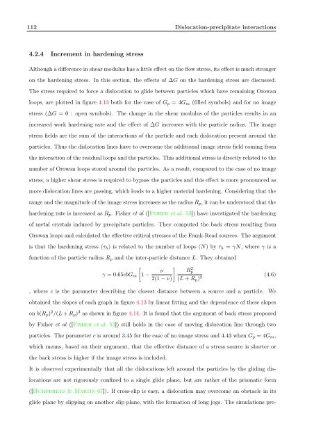
is that the hardening stress (τh) is related to the number of loops (N) by τh = γN, where γ is a<br />
function of the particle radius Rp and the inter-particle distance L. They obtained<br />
γ = 0.65cbGm<br />
<br />
1 −<br />
<br />
ν<br />
2(1 − ν)<br />
R 2 p<br />
(L + Rp) 3<br />
, where c is the parameter describing the closest distance between a source and a particle. We<br />
obtained the slopes of each graph in figure 4.13 by linear fitting and the dependence of these slopes<br />
on b(Rp) 2 /(L + Rp) 3 as shown in figure 4.14. It is found that the argument of back stress proposed<br />
by Fisher et al ([Fisher et al. 53]) still holds in the case of moving dislocation line through two<br />
particles. The parameter c is around 3.45 for the case of no image stress and 4.43 when Gp = 4Gm,<br />
which means, based on their argument, that the effective distance of a stress source is shorter or<br />
the back stress is higher if the image stress is included.<br />
It is observed experimentally that all the dislocations left around the particles by the gliding dis-<br />
locations are not rigorously confined to a single glide plane, but are rather of the prismatic form<br />
([Humphreys & Martin 67]). If cross-slip is easy, a dislocation may overcome an obstacle in its<br />
glide plane by slipping on another slip plane, with the formation of long jogs. The simulations pre-<br />
(4.6)


